EP1034740A1 - Apparatus for taking blood for diagnostic purposes - Google Patents
Apparatus for taking blood for diagnostic purposes Download PDFInfo
- Publication number
- EP1034740A1 EP1034740A1 EP00102503A EP00102503A EP1034740A1 EP 1034740 A1 EP1034740 A1 EP 1034740A1 EP 00102503 A EP00102503 A EP 00102503A EP 00102503 A EP00102503 A EP 00102503A EP 1034740 A1 EP1034740 A1 EP 1034740A1
- Authority
- EP
- European Patent Office
- Prior art keywords
- lancet
- blood collection
- collection device
- drive rotor
- movement
- Prior art date
- Legal status (The legal status is an assumption and is not a legal conclusion. Google has not performed a legal analysis and makes no representation as to the accuracy of the status listed.)
- Granted
Links
Images


Classifications
-
- A—HUMAN NECESSITIES
- A61—MEDICAL OR VETERINARY SCIENCE; HYGIENE
- A61B—DIAGNOSIS; SURGERY; IDENTIFICATION
- A61B5/00—Measuring for diagnostic purposes; Identification of persons
- A61B5/15—Devices for taking samples of blood
- A61B5/151—Devices specially adapted for taking samples of capillary blood, e.g. by lancets, needles or blades
- A61B5/15186—Devices loaded with a single lancet, i.e. a single lancet with or without a casing is loaded into a reusable drive device and then discarded after use; drive devices reloadable for multiple use
- A61B5/15188—Constructional features of reusable driving devices
- A61B5/1519—Constructional features of reusable driving devices comprising driving means, e.g. a spring, for propelling the piercing unit
-
- A—HUMAN NECESSITIES
- A61—MEDICAL OR VETERINARY SCIENCE; HYGIENE
- A61B—DIAGNOSIS; SURGERY; IDENTIFICATION
- A61B5/00—Measuring for diagnostic purposes; Identification of persons
- A61B5/15—Devices for taking samples of blood
- A61B5/150007—Details
- A61B5/150015—Source of blood
- A61B5/150022—Source of blood for capillary blood or interstitial fluid
-
- A—HUMAN NECESSITIES
- A61—MEDICAL OR VETERINARY SCIENCE; HYGIENE
- A61B—DIAGNOSIS; SURGERY; IDENTIFICATION
- A61B5/00—Measuring for diagnostic purposes; Identification of persons
- A61B5/15—Devices for taking samples of blood
- A61B5/150007—Details
- A61B5/150175—Adjustment of penetration depth
- A61B5/150183—Depth adjustment mechanism using end caps mounted at the distal end of the sampling device, i.e. the end-caps are adjustably positioned relative to the piercing device housing for example by rotating or screwing
-
- A—HUMAN NECESSITIES
- A61—MEDICAL OR VETERINARY SCIENCE; HYGIENE
- A61B—DIAGNOSIS; SURGERY; IDENTIFICATION
- A61B5/00—Measuring for diagnostic purposes; Identification of persons
- A61B5/15—Devices for taking samples of blood
- A61B5/150007—Details
- A61B5/150374—Details of piercing elements or protective means for preventing accidental injuries by such piercing elements
- A61B5/150381—Design of piercing elements
- A61B5/150412—Pointed piercing elements, e.g. needles, lancets for piercing the skin
- A61B5/150435—Specific design of proximal end
-
- A—HUMAN NECESSITIES
- A61—MEDICAL OR VETERINARY SCIENCE; HYGIENE
- A61B—DIAGNOSIS; SURGERY; IDENTIFICATION
- A61B5/00—Measuring for diagnostic purposes; Identification of persons
- A61B5/15—Devices for taking samples of blood
- A61B5/151—Devices specially adapted for taking samples of capillary blood, e.g. by lancets, needles or blades
- A61B5/15101—Details
- A61B5/15103—Piercing procedure
- A61B5/15107—Piercing being assisted by a triggering mechanism
- A61B5/15113—Manually triggered, i.e. the triggering requires a deliberate action by the user such as pressing a drive button
-
- A—HUMAN NECESSITIES
- A61—MEDICAL OR VETERINARY SCIENCE; HYGIENE
- A61B—DIAGNOSIS; SURGERY; IDENTIFICATION
- A61B5/00—Measuring for diagnostic purposes; Identification of persons
- A61B5/15—Devices for taking samples of blood
- A61B5/151—Devices specially adapted for taking samples of capillary blood, e.g. by lancets, needles or blades
- A61B5/15101—Details
- A61B5/15115—Driving means for propelling the piercing element to pierce the skin, e.g. comprising mechanisms based on shape memory alloys, magnetism, solenoids, piezoelectric effect, biased elements, resilient elements, vacuum or compressed fluids
- A61B5/15117—Driving means for propelling the piercing element to pierce the skin, e.g. comprising mechanisms based on shape memory alloys, magnetism, solenoids, piezoelectric effect, biased elements, resilient elements, vacuum or compressed fluids comprising biased elements, resilient elements or a spring, e.g. a helical spring, leaf spring, or elastic strap
-
- A—HUMAN NECESSITIES
- A61—MEDICAL OR VETERINARY SCIENCE; HYGIENE
- A61B—DIAGNOSIS; SURGERY; IDENTIFICATION
- A61B5/00—Measuring for diagnostic purposes; Identification of persons
- A61B5/15—Devices for taking samples of blood
- A61B5/150007—Details
- A61B5/150206—Construction or design features not otherwise provided for; manufacturing or production; packages; sterilisation of piercing element, piercing device or sampling device
- A61B5/150259—Improved gripping, e.g. with high friction pattern or projections on the housing surface or an ergonometric shape
Definitions
- the invention relates to a blood lancet device for removal of blood for diagnostic purposes.
- blood sugar intensive therapy is long-term only as part of the so-called "home monitoring", that is, by the patient or their relatives without trained medical personnel, possible. It is the patient's willingness and ability, at least Blood sampling four times a day using a lancet perform, crucially from the properties dependent on the blood collection device. It has to be constructed that way be that the pain in generating the blood for required wound is as small as possible.
- the Handling the device must be as simple as possible, especially because many of the patients affected because of their Illness or because of advanced age not in are able to perform difficult handling operations precisely. Furthermore, it is light in weight and one practical form important to the device without essential To be able to carry the load constantly. After all, it should the construction is as simple, durable and inexpensive as possible his.
- the invention is based on the object to create an improved blood collection device that the entirety of the requirements mentioned better than fulfilled so far.
- a device for removing Blood for diagnostic purposes with an elongated housing, at the front end an outlet for the Tip of a lancet is provided, one in the housing in the direction of its major axis along a predetermined one Insertion path movable lancet holder for holding the lancet, a lancet guide for guidance the lancet holder on the predetermined insertion path and a lancet drive with an elastic drive spring, the tensioned state of the mainspring can be locked by means of a locking device and by the relaxation movement after releasing the locking device the mainspring into a puncturing movement is implemented in which the lancet holder held lancet at high speed along the predetermined insertion path in the insertion direction is moved until its tip comes out of the exit opening exits to in an adjacent to the outlet opening Body part to create a wound, in which in the housing a double-sided rotary slide transmission is provided is on the input side of which the movement of one from the Housing on the rear end of the protruding tension button along
- the invention also relates to a blood collection kit, the as coordinated system components comprises a blood collection device according to the invention and lancets, to the holder in the lancet holder of the device are trained.
- blood collection kits which one can also be called blood collection equipment
- Such blood collection kits (which one can also be called blood collection equipment) (as original equipment) in the form of packaging units sold, which contain both system components. Since the Lancets can usually only be used once them for further use also in separate Packaging for use with one already at the user existing blood collection device offered.
- the term "gear” is understood here in the general sense, i.e. as a kinematic device used for Coupling and conversion of movements serves. In the present Case is due to the double-sided rotary gear on the one hand a translatory movement of the Clamping button in a rotational movement of the lancet drive rotor and on the other hand a rotational movement of the Lancet drive rotor in a translational movement of the Lancet holder transformed with the lancet.
- This Gear functions can basically be done with the help of the machine construction theory known construction elements will be realized.
- the lancet drive rotor has one helical as a spiral Sliding surface and the tension button a tension cam on that by means of a contact surface on the surface the helix slides for a linear movement of the tension knob into a rotational movement of the lancet drive rotor implement.
- the coil is preferably on formed an adapter sleeve that part of the drive rotor forms and their facing the outlet opening front end surrounds the lancet holder.
- a particularly simple construction and low vibration Function is achieved when according to another preferred one Embodiment at the front end of the adapter sleeve a control curve is provided which cooperates with one provided on the lancet holder Control pin the puncture movement and preferably also the Return movement of the lancet holder and the ones held therein Lancet controls.
- the control of the puncture and Return movement through the interaction of a control pin and a control curve is from those mentioned above U.S. Patents 5,318,584 and 5,554,106 are known.
- FIG. 1 in the form of a schematic diagram shown blood collection device 1 has an elongated Housing 2, which is along the main axis of the device A extends.
- the front end 3 of the housing 2 is one removable cap 4 is formed in the outlet opening 5 provided for the tip 6 of a lancet 7 is.
- the lancet 7 is held by a lancet holder 8 in such a way that the tip 6 related to the holder 8 also then reproducibly in the same position if one for consecutive blood draws new lancet 7 is inserted into the holder 8.
- advantageous Measures to achieve this, also for the present invention can be used are in U.S. Patent 5,318,584.
- the front end 3 of the housing 2 pressed against a part of the body in which there is a wound to generate a drop of blood.
- the lancet holder 8 then performs a puncturing movement in which the lancet held by the lancet holder 8 7 at high speed along one preferably predetermined along the major axis A. Insertion path in the insertion direction symbolized by arrow 10 is moved until its tip 6 out of the outlet opening 5 emerges and penetrates into the body part.
- lancet drive the central element of which is a lancet drive rotor 13 is in the housing 2 by means of a rotary bearing 14 in a fixed axial position, but around the main axis A rotatable, is stored.
- the lancet drive rotor 13 is under the action of a drive spring 15, formed as the torsion spring surrounding the drive rotor 14 is.
- One end of the drive spring 15 is on the Lancet drive rotor 13, the other end to the housing 2 attached.
- the drive spring 15 is by one of its spring force counter rotating rotation of the lancet drive rotor 13 curious; excited. In the case shown, this is considered from the rear end 16 of the housing - a left turn of the Rotor 13 required.
- This tension movement is thereby causes a from the housing 2 at the rear end 16 more outstanding, in the opposite direction from a return spring 18 loaded knob 17 along the main axis A is moved towards the front end 3.
- Clamping cams 20 via a formed on the drive rotor 13 in the form of a helical spiral 21 Sliding surface 22.
- the tension button 17 and with it the Tensioning cams 20 are axially displaceable, but are rotationally fixed stored.
- the output side 26 of the double-sided rotary slide transmission 25 is designed so that after triggering the Lancet drive by means of a release button 27 (the Function is not shown in Figure 1) one by the Drive spring 15 driven rotational movement of the lancet drive rotor 13 in the puncture movement 10 in Direction of the main axis A is implemented.
- a curve control designated overall by 28 provided by a control curve 30 and an in the control curve 30 matching control pin 31 is formed is.
- the control pin 31 is with the lancet holder 8 firmly connected, which in turn is axially displaceable is rotationally fixed.
- the control curve 30 is from a recess 32 of the lancet drive rotor 13 is formed.
- control curve is a component of the lancet holder and the control pin rotates, it is in the present invention - as shown - preferably vice versa: the control pin is with the lancet holder 8 is firmly connected and axially movable, while the control cam 30 with the lancet drive rotor 13 rotates.
- Figures 2 to 8 show different representations a particularly advantageous practical embodiment of a blood collection device according to the invention. It deals each of these is based on scaled representations, i.e. the proportions of the components correspond to each other in each of the figures the actual circumstances.
- the rotary bearing 14 expediently by a on the lancet drive rotor 13 formed from its peripheral surface projecting bearing ring 35 and a corresponding one Paragraph 36 of the housing 2 is formed.
- the bearing ring 35 has an interruption into which a first Leg 37 of the drive spring 15 engages.
- the second Leg 38 is fixed to the housing 2.
- the lancet drive is 12 of two axially pluggable housing parts, namely a front housing part 44 and a rear housing part 45 surrounded.
- a Clip 46 attached with which the blood collection device 1, for example can be attached in a jacket pocket.
- a lower insert 47 used, which has a central axial opening 48, the inner contour of the outer contour of the lancet holder 8 corresponds.
- the walls of the axial opening 48 form a precise guide 49 for the puncture and Return movement of the lancet holder 8.
- the lower end of the insert 47 is from an adjusting ring 50 surrounded, on the outside of a thread 51 is provided, onto which the cap 4 is screwed becomes.
- the locking device 19 is in the illustrated embodiment realized in such a way that the lancet drive rotor 13 has a spring tab 40, of the a short locking pin 41 protrudes radially outwards, the one for locking the lancet drive in the cocked position State of the spring 15 in a corresponding recess 42 of the housing part 44 engages.
- the trigger button is used to trigger 27 with its lower trigger End pressed into the recess 42 so that the locking pin 41 becomes free.
- the trigger button 27 is preferred transparent, so that the locking pin in the tensioned state 41 and possibly also parts of the spring tab 40 through the release button 27 are recognizable.
- This Components are preferably with a contrasting Color (for example yellow or red) colored. Thereby is the tensioned state of the blood collection device in a simple manner 1 recognizable.
- the lower housing part 44 and the cap 4 are partial surrounded by an ejector sleeve 55, by means of which the lancet 7 can be ejected from the holder 8 after previously the cap 4 including the adjusting ring 50 on lower end of the housing 2 was removed.
- the slope of the helix 21 can best be seen (i.e. the angle ⁇ between the sliding surface and one too the sliding axis in the respective vertical axis Point intersecting straight line) over the length of the Span 23 is not constant, but variable.
- the contact surface 57 of the clamping cam 20 is preferred so inclined that at least part of the Front end of the housing facing half of the helix length There is surface contact with the helix.
- the inclination is correct the contact surface 57 with the slope of the sliding surface 22 in their front (lower in FIG. 6) section. This makes it particularly easy to slide and less Wear in the area of the clamping process reached, in which the highest counterforce of the spring 15 acts.
- a plastic based is preferred for the former a polyacetal, in particular based on a polyoxymethylene (POM) used while for the latter one Plastic based on a styrene-acrylonitrile copolymer (SAN) is particularly suitable.
- the Lancet drive rotor 13 made of two parts, namely one Adapter sleeve 59 and one that can be inserted into it from the front Curve sleeve 60 is made.
- the front end of the adapter sleeve 59 encloses with the curve sleeve 60 inserted therein the rear end of the lancet holder 8 in the Area where this two diametrically opposite Control pin 31 has.
- the clamping sleeve 59 and the cam sleeve used therein 60 become two recesses of the lancet drive rotor 13 formed, the boundary edges together define a control curve.
- the recesses 61 and 62 are designed so that in every phase of the rotational movement one of the recesses 61 guiding the one Control pin to the rear and the other recess 62 forms the guide of the control pin to the front.
- this is shown in FIG. 7 raised area piece 63 with its rear edge 63a a limitation for the movement of a control pin 31 forward during the feedback phase, i.e. the Possibility of moving the lancet holder 8 forward by the rear edges 63a of the raised sheet 63 limited.
- the limit accordingly facing edges 63b of the raised surface piece 63 die Possibility of movement of the lancet holder 8 during the Puncture and return phase backwards.
- the boundaries 63a, 63b, 64a, 64b form that on the inner wall of the lancet drive rotor 13 formed recesses 61 and 62 a common control curve, driven by the two control pins 31 becomes.
- This preferred embodiment makes one extreme slim design possible.
- both Helical sliding surface 22 as well as the control curve 30 on one stare uniformly (only for manufacturing reasons consisting of the adapter sleeve 59 and the cam sleeve 60) Component trained.
- a rigid one Construction of the drive rotor 13 is preferred in principle, a design is also possible in which the required rotation coupling between the control curve 30 and the spiral sliding surface 22 indirectly, for example is effected via a connecting rod.
- a drive rotor in the sense of the invention is always about the main axis to understand rotating unit regardless of whether it consists of one or more components.
- the tensioning cam 20 is preferably, as shown, on one integrally formed component that the tension button 17 forms. This is also not absolutely necessary. It constructions are also possible in which the clamping cam 20 and the release button 16 on separate components are provided, which, however, are connected to each other in this way must be that the clamping cam 20 when actuated of the tension button 17 in synchronism with this along the linear span 23 is moved.
- the blood collection device according to the invention can overall be very slim.
- the largest diameter of the Blood collection device should in any case be less than 20 mm. A value of less than 15 mm is also used the construction according to the invention possible.
Abstract
Description
Die Erfindung betrifft ein Blutlanzettengerät zur Entnahme von Blut für Diagnosezwecke.The invention relates to a blood lancet device for removal of blood for diagnostic purposes.
Um für Diagnosezwecke eine geringe Menge Blut aus einem Körperteil (üblicherweise dem Finger oder dem Ohrläppchen) zu entnehmen, werden Lanzetten verwendet, die in das entsprechende Körperteil gestochen werden. Das Einstechen erfolgte in der Vergangenheit durch trainiertes, speziell ausgebildetes Personal manuell oder mit einer einfachen Apparatur. Soweit die Blutuntersuchungen nur in relativ großen zeitlichen Abständen durchgeführt werden müssen, ist diese Form der Blutgewinnung akzeptabel, weil der Schmerz, der mit dem Einstechen verbunden ist, dabei keine entscheidende Rolle spielt.To get a small amount of blood out of one for diagnostic purposes Body part (usually the finger or earlobe) to remove, lancets are used, which in the corresponding part of the body is stung. The stabbing has been done in the past by trained specially trained personnel manually or with a simple equipment. As far as the blood tests only in relatively large intervals need, this form of blood collection is acceptable because the pain associated with the stabbing doesn't matter.
Wesentlich höhere Anforderungen sind an die Blutentnahme
zu stellen, wenn eine regelmäßige Überwachung bestimmter
analytischer Werte des Blutes von Patienten erforderlich
ist. Dies gilt insbesondere für Diabetiker, die ihren
Blutzuckerspiegel häufig und regelmäßig kontrollieren
sollten, um durch Anpassung von Insulininjektionen an den
Bedarf (der von der Nahrungsaufnahme, der körperlichen
Aktivität und anderen Faktoren abhängt) ihren Blutzuckerspiegel
möglichst ständig innerhalb bestimmter Sollgrenzen
zu halten. Diese Blutzucker-Intensivtherapie ist für
die Gesundheit der Patienten von größter Bedeutung und
erfordert mindestens vier Blutentnahmen pro Tag. Beispielsweise
wird in der Publikation
Die Blutzucker-Intensivtherapie ist in der Praxis längerfristig nur im Rahmen des sogenannten "home-monitoring", also durch den Patienten oder dessen Angehörige ohne trainiertes medizinisches Personal, möglich. Dabei ist die Bereitschaft und Fähigkeit des Patienten, mindestens viermal täglich eine Blutentnahme mittels einer Lanzette durchzuführen, ganz entscheidend von den Eigenschaften des Blutentnahmegerätes abhängig. Es muß so konstruiert sein, daß der Schmerz bei der Erzeugung der für die Blutentnahme erforderlichen Wunde möglichst gering ist. Die Handhabung des Gerätes muß möglichst einfach sein, insbesondere weil viele der betroffenen Patienten wegen ihrer Erkrankung oder wegen fortgeschrittenen Alters nicht in der Lage sind, diffizile Handhabungsvorgänge präzise auszuführen. Weiterhin ist ein geringes Gewicht und eine praktische Form wichtig, um das Gerät ohne wesentliche Belastung ständig mitführen zu können. Schließlich soll die Konstruktion möglichst einfach, langlebig und kostengünstig sein.In practice, blood sugar intensive therapy is long-term only as part of the so-called "home monitoring", that is, by the patient or their relatives without trained medical personnel, possible. It is the patient's willingness and ability, at least Blood sampling four times a day using a lancet perform, crucially from the properties dependent on the blood collection device. It has to be constructed that way be that the pain in generating the blood for required wound is as small as possible. The Handling the device must be as simple as possible, especially because many of the patients affected because of their Illness or because of advanced age not in are able to perform difficult handling operations precisely. Furthermore, it is light in weight and one practical form important to the device without essential To be able to carry the load constantly. After all, it should the construction is as simple, durable and inexpensive as possible his.
Um diesen Anforderungen gerecht zu werden, wurden bereits
eine Vielzahl von Gestaltungen und Konstruktionen von
Blutentnahmegeräten und zugehörigen Lanzetten vorgeschlagen,
die beispielsweise in den US-Patenten
Obwohl durch diese Konstruktionen wesentliche Verbesserungen bei der Blutentnahme für Diagnosezwecke erreicht werden konnten, können sie hinsichtlich der Gesamtheit der vorgenannten Anforderungen nicht in vollem Umfang befriedigen. Insbesondere sind bei denjenigen Geräten, bei denen die Erzeugung der Wunde mit sehr geringen Schmerzen verbunden ist, Nachteile hinsichtlich der Handhabung und/oder Geräteform- und größe festzustellen. Umgekehrt wird mit besonders kleinen und einfach bedienbaren Geräten keine befriedigende Schmerzarmut erreicht.Although significant improvements through these constructions reached during blood collection for diagnostic purposes they can be in terms of the whole not fully satisfy the aforementioned requirements. In particular, with those devices, at those producing the wound with very little pain connected, disadvantages in terms of handling and / or Determine device shape and size. Conversely with particularly small and easy-to-use devices no satisfactory pain relief was achieved.
Der Erfindung liegt auf dieser Basis die Aufgabe zugrunde, ein verbessertes Blutentnahmegerät zu schaffen, das die Gesamtheit der genannten Anforderungen besser als bisher erfüllt.On this basis, the invention is based on the object to create an improved blood collection device that the entirety of the requirements mentioned better than fulfilled so far.
Die Aufgabe wird gelöst durch ein Gerät zur Entnahme von Blut für Diagnosezwecke, mit einem langgestreckten Gehäuse, an dessen Vorderende eine Austrittsöffnung für die Spitze einer Lanzette vorgesehen ist, einem in dem Gehäuse in Richtung von dessen Hauptachse entlang einem vorbestimmten Einstichweg beweglichen Lanzettenhalter zur Halterung der Lanzette, einer Lanzettenführung zur Führung des Lanzettenhalters auf dem vorbestimmten Einstichweg und einem Lanzettenantrieb mit einer elastischen Antriebsfeder, der im gespannten Zustand der Antriebsfeder mittels einer Arretiervorrichtung arretierbar ist und durch den nach dem Lösen der Arretiervorrichtung die Entspannungsbewegung der Antriebsfeder in eine Einstichbewegung umgesetzt wird, bei der die von dem Lanzettenhalter gehaltene Lanzette mit hoher Geschwindigkeit entlang dem vorbestimmten Einstichweg in Einstichrichtung bewegt wird, bis ihre Spitze aus der Austrittsöffnung austritt, um in einem an der Austrittsöffnung anliegenden Körperteil eine Wunde zu erzeugen, bei welchem in dem Gehäuse ein doppelseitiges Drehschiebegetriebe vorgesehen ist, auf dessen Eingangsseite die Bewegung eines aus dem Gehäuse an dessen Hinterende herausragenden Spannknopfes längs eines linearen Spannweges in eine Drehbewegung eines Lanzettenantriebsrotors umgesetzt wird, der um eine zu der Geräteachse parallel verlaufende Rotationsachse gedreht wird, um den Lanzettenantriebsrotor gegen die Kraft der Antriebsfeder zu spannen und auf dessen Ausgangsseite nach dem Auslösen des Lanzettenantriebs eine durch die Antriebefeder angetriebene Rotationsbewegung des Lanzettenantriebsrotors in die Einstichbewegung in Richtung der Hauptachse umgesetzt wird. The task is solved by a device for removing Blood for diagnostic purposes, with an elongated housing, at the front end an outlet for the Tip of a lancet is provided, one in the housing in the direction of its major axis along a predetermined one Insertion path movable lancet holder for holding the lancet, a lancet guide for guidance the lancet holder on the predetermined insertion path and a lancet drive with an elastic drive spring, the tensioned state of the mainspring can be locked by means of a locking device and by the relaxation movement after releasing the locking device the mainspring into a puncturing movement is implemented in which the lancet holder held lancet at high speed along the predetermined insertion path in the insertion direction is moved until its tip comes out of the exit opening exits to in an adjacent to the outlet opening Body part to create a wound, in which in the housing a double-sided rotary slide transmission is provided is on the input side of which the movement of one from the Housing on the rear end of the protruding tension button along a linear clamping path in a rotational movement of a Lancet drive rotor is implemented by a axis of rotation parallel to the device axis is rotated against the lancet drive rotor Force the mainspring to tension and on its output side after triggering the lancet drive one rotational movement driven by the drive spring of the lancet drive rotor into the puncture movement in Direction of the main axis is implemented.
Die Erfindung richtet sich auch auf einen Blutentnahme-Kit, der als aufeinander abgestimmte Systembestandteile ein erfindungsgemäßes Blutentnahmegerät und Lanzetten umfaßt, die zur Halterung in dem Lanzettenhalter des Gerätes ausgebildet sind. Solche Blutentnahme-Kits (die man auch als Blutentnahme-Ausrüstung bezeichnen kann) werden (als Erstausrüstung) in Form von Verpackungseinheiten verkauft, die beide Systembestandteile enthalten. Da die Lanzetten üblicherweise nur einmal verwendbar sind, werden sie für den weiteren Gebrauch auch in gesonderter Verpackung zur Verwendung mit einem bei dem Benutzer bereits vorhandenen Blutentnahmegerät angeboten.The invention also relates to a blood collection kit, the as coordinated system components comprises a blood collection device according to the invention and lancets, to the holder in the lancet holder of the device are trained. Such blood collection kits (which one can also be called blood collection equipment) (as original equipment) in the form of packaging units sold, which contain both system components. Since the Lancets can usually only be used once them for further use also in separate Packaging for use with one already at the user existing blood collection device offered.
Der Begriff "Getriebe" wird hier im allgemeinen Sinn verstanden, d.h. als eine kinematische Vorrichtung, die zur Kopplung und Umwandlung von Bewegungen dient. Im vorliegenden Fall wird durch das doppelseitige Drehschiebegetriebe einerseits eine translatorische Bewegung des Spannknopfes in eine Rotationsbewegung des Lanzettenantriebsrotors und andererseits eine Rotationsbewegung des Lanzettenantriebsrotors in eine Translationsbewegung des Lanzettenhalters mit der Lanzette transformiert. Diese Getriebefunktionen können grundsätzlich mit Hilfe von aus der Maschinenkonstruktionslehre bekannten Konstrukionselementen realisiert werden.The term "gear" is understood here in the general sense, i.e. as a kinematic device used for Coupling and conversion of movements serves. In the present Case is due to the double-sided rotary gear on the one hand a translatory movement of the Clamping button in a rotational movement of the lancet drive rotor and on the other hand a rotational movement of the Lancet drive rotor in a translational movement of the Lancet holder transformed with the lancet. This Gear functions can basically be done with the help of the machine construction theory known construction elements will be realized.
Durch die Erfindung werden unter anderem folgende Vorteile erreicht:
- Die Konstruktion ermöglicht eine sehr schlanke Gehäuseform ähnlich einem Kugelschreiber (sogenannte "pencil-form"). Das Gerät ist dadurch unauffällig und leicht transportabel.
- Das Gerät kann hinsichtlich des Spann- und hinsichtlich des Auslösevorgangs mit nur einer Hand bedient werden.
- Die Handhabung ist leicht und intuitiv.
- Der Schmerz bei der Erzeugung der Wunde ist sehr gering. Dies ist teilweise darauf zurückzuführen, daß eine sehr gute Vibrationsarmut erreicht wird.
- Trotz der wesentlichen Verbesserung der Funktion ist die Konstruktion einfach und kostengünstig.
- The design enables a very slim housing shape similar to a ballpoint pen (so-called "pencil-form"). This makes the device inconspicuous and easy to transport.
- The device can be operated with only one hand in terms of the clamping and triggering process.
- Handling is easy and intuitive.
- The pain when creating the wound is very slight. This is partly due to the fact that very low levels of vibration are achieved.
- Despite the significant improvement in function, the construction is simple and inexpensive.
Bei der Realisierung der Erfindung sind besondere Probleme zu berücksichtigen, die vor allem daraus resultieren, daß ein schmerzarmer Einstich eine sehr schnelle und präzise geführte Einstichbewegung voraussetzt. Um diese zu ermöglichen, muß die Antriebsfeder eine hohe Federkraft ausüben. Andererseits soll die Betätigung des Spannknopfes so leicht sein, daß auch ältere und körperlich eingeschränkte Personen das Blutentnahmegerät problemlos spannen können.There are particular problems in realizing the invention to take into account, which mainly result from that a painless puncture is a very quick and requires precisely guided puncture movement. Around To enable, the drive spring must have a high spring force exercise. On the other hand, the actuation of the Tension button so light that even older and physically restricted people use the blood collection device without any problems can tension.
Diese Probleme werden besonders gut gelöst und die oben genannten Vorteile werden in besonderem Maße erreicht, wenn die in der nachfolgenden Beschreibung und in den Unteransprüchen genannten Merkmale bevorzugter Ausgestaltungen realisiert werden. Diese Merkmale können einzeln oder in Kombination bei dem erfindungsgemäßen Blutentnahmegerät vorhanden sein.These problems are solved particularly well and the above mentioned advantages are achieved to a particular degree, if the in the following description and in the subclaims mentioned features of preferred embodiments will be realized. These features can be used individually or in combination in the blood collection device according to the invention to be available.
Gemäß einer bevorzugten Ausführungsform weist der Lanzettenantriebsrotor eine schraubenförmig als Wendel verlaufende Gleitfläche und der Spannknopf einen Spannocken auf, der mittels einer Kontaktfläche auf der Oberfläche der Wendel gleitet, um eine Linearbewegung des Spannknopfes in eine Rotationsbewegung des Lanzettenantriebsrotors umzusetzen. Dabei ist vorzugsweise die Wendel an einer Spannhülse ausgebildet, die einen Teil des Antriebsrotors bildet und deren der Austrittsöffnung zugewandtes vorderes Ende den Lanzettenhalter umgibt.According to a preferred embodiment, the lancet drive rotor has one helical as a spiral Sliding surface and the tension button a tension cam on that by means of a contact surface on the surface the helix slides for a linear movement of the tension knob into a rotational movement of the lancet drive rotor implement. The coil is preferably on formed an adapter sleeve that part of the drive rotor forms and their facing the outlet opening front end surrounds the lancet holder.
Eine besonders einfache Konstruktion und vibrationsarme Funktion wird erreicht, wenn gemäß einer weiteren bevorzugten Ausführungsform an dem vorderen Ende der Spannhülse eine Steuerkurve vorgesehen ist, die im Zusammenwirken mit einem an dem Lanzettenhalter vorgesehenen Steuerzapfen die Einstichbewegung und bevorzugt auch die Rückführbewegung des Lanzettenhalters und der darin gehaltenen Lanzette steuert. Die Steuerung der Einstich- und Rückführbewegung durch das Zusammenwirken eines Steuerzapfens und einer Steuerkurve ist aus den oben erwähnten US-Patentschriften 5,318,584 und 5,554,106 bekannt.A particularly simple construction and low vibration Function is achieved when according to another preferred one Embodiment at the front end of the adapter sleeve a control curve is provided which cooperates with one provided on the lancet holder Control pin the puncture movement and preferably also the Return movement of the lancet holder and the ones held therein Lancet controls. The control of the puncture and Return movement through the interaction of a control pin and a control curve is from those mentioned above U.S. Patents 5,318,584 and 5,554,106 are known.
Die Erfindung wird nachfolgend anhand eines in den Figuren dargestellten Ausführungsbeispieles näher erläutert; es zeigen:
- Fig. 1
- eine Prinzipdarstellung eines Blutentnahmegerätes im Querschnitt,
- Fig. 2
- eine Seitenansicht eines Blutentnahmegerätes,
- Fig. 3
- einen Querschnitt des
Blutentnahmegerätes von Figur 2 mit in den Lanzettenhalter eingesetzter Lanzette, - Fig. 4
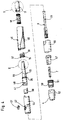
- eine Explosionsdarstellung der für die Funktion gemäß der vorliegenden Erfindung wesentlichen Bauteile eines Blutentnahmegerätes,
- Fig. 5
- eine Detaildarstellung des hinteren Endes des
in
Figur 4 dargestellten Lanzettenantriebsrotors und des inFigur 4 dargestellten Spannknopfes, wobei letzterer aufgeschnitten ist, - Fig. 6
- eine Abwicklung der Wendel der in
den Figuren 2 und 3 dargestellten Spannhülse in eine Ebene. - Fig. 7
- eine erste aufgeschnittene Ansicht einer in
Figur 4 dargestellten Spannhülse mit darin eingesetzter Kurvenhülse, und - Fig. 8
- eine zweite aufgeschnittene Ansicht der Spann- und
Kurvenhülse von Figur 7.
- Fig. 1
- a schematic diagram of a blood collection device in cross section,
- Fig. 2
- a side view of a blood collection device,
- Fig. 3
- 3 shows a cross section of the blood collection device from FIG. 2 with the lancet inserted in the lancet holder,
- Fig. 4
- 2 shows an exploded view of the components of a blood collection device that are essential for the function according to the present invention,
- Fig. 5
- 4 shows a detailed representation of the rear end of the lancet drive rotor shown in FIG. 4 and of the tensioning button shown in FIG. 4, the latter being cut open,
- Fig. 6
- a development of the helix of the clamping sleeve shown in Figures 2 and 3 in one plane.
- Fig. 7
- a first cut view of an adapter sleeve shown in Figure 4 with a curved sleeve inserted therein, and
- Fig. 8
- 7 shows a second cutaway view of the clamping and curve sleeve from FIG. 7.
Das in Figur 1 in Form einer schematischen Prinzipdarstellung
gezeigte Blutentnahmegerät 1 hat ein langgestrecktes
Gehäuse 2, das sich längs der Geräte-Hauptachse
A erstreckt. Das Vorderende 3 des Gehäuses 2 wird von einer
abnehmbaren Kappe 4 gebildet, in der eine Austrittsöffnung
5 für die Spitze 6 einer Lanzette 7 vorgesehen
ist.This in Figure 1 in the form of a schematic diagram
shown
Die Lanzette 7 wird von einem Lanzettenhalter 8 so gehalten,
daß sich die Spitze 6 bezogen auf den Halter 8 auch
dann reproduzierbar in der gleichen Position befindet,
wenn für aufeinanderfolgende Blutentnahmen jeweils eine
neue Lanzette 7 in den Halter 8 eingesetzt wird. Vorteilhafte
Maßnahmen, um dies zu erreichen, die auch für die
vorliegende Erfindung verwendet werden können, sind in
dem US-Patent 5,318,584 beschrieben.The
Zum Erzeugen einer Wunde wird das Vorderende 3 des Gehäuses
2 gegen ein Körperteil gedrückt, in dem eine Wunde
zur Gewinnung eines Blutstropfens erzeugt werden soll.
Danach führt der Lanzettenhalter 8 eine Einstichbewegung
aus, bei der die von dem Lanzettenhalter 8 gehaltene Lanzette
7 mit hoher Geschwindigkeit entlang einem vorzugsweise
längs der Hauptachse A verlaufenden vorbestimmten
Einstichweg in die durch den Pfeil 10 symbolisierte Einstichrichtung
bewegt wird, bis ihre Spitze 6 aus der Austrittsöffnung
5 austritt und in das Körperteil eindringt. To create a wound, the
Danach wird die Lanzette 7 in der durch den Pfeil 11 symbolisierten
Rückführungsrichtung in die Ausgangslage zurückbewegt.Then the
Die Einstich- und Rückführungsbewegung des Lanzettenhalters
8 (und somit der Lanzette 7) wird durch einen insgesamt
mit 12 bezeichneten Lanzettenantrieb angetrieben,
dessen zentrales Element ein Lanzettenantriebsrotor 13
ist, der in dem Gehäuse 2 mittels eines Rotationslagers
14 in einer festen Axialposition, jedoch um die Hauptachse
A rotierbar, gelagert ist. Der Lanzettenantriebsrotor
13 steht unter der Wirkung einer Antriebsfeder 15,
die als den Antriebsrotor 14 umgebende Torsionsfeder ausgebildet
ist. Ein Ende der Antriebsfeder 15 ist an dem
Lanzettenantriebsrotor 13, das andere Ende an dem Gehäuse
2 befestigt.The lancing and return movement of the lancet holder
8 (and thus the lancet 7) is replaced by a total
driven with 12 designated lancet drive,
the central element of which is a
Die Antriebsfeder 15 wird durch eine ihrer Federkraft
entgegenwirkende Drehung des Lanzettenantriebsrotors 13
gespannt. Im dargestellten Fall ist hierzu - betrachtet
vom Hinterende 16 des Gehäuses - eine Linksdrehung des
Rotors 13 erforderlich. Diese Spannbewegung wird dadurch
bewirkt, daß ein aus dem Gehäuse 2 an dessen Hinterende
16 herausragender, in der Gegenrichtung von einer Rückstellfeder
18 belasteter Spannknopf 17 längs der Hauptachse
A in Richtung auf das Vorderende 3 bewegt wird. Dabei
gleitet ein mit dem Spannknopf 17 fest verbundener
Spannocken 20 über eine an dem Antriebsrotor 13 ausgebildete
in Form einer schraubenförmigen Wendel 21 verlaufende
Gleitfläche 22. Der Spannknopf 17 und mit ihm der
Spannocken 20 sind axial verschiebbar, jedoch rotationsfest
gelagert. Dies führt in Verbindung mit der Form der
Wendel 21 dazu, daß die Bewegung des Spannknopfes 17
längs eines linearen durch den Pfeil 23 symbolisierten
Spannweges in eine Rotationsbewegung des Lanzettenantriebsrotors
um eine zu der Hauptachse parallel verlaufende
Rotationsachse umgesetzt wird, um den Lanzettenantriebsrotor
13 gegen die Kraft der Antriebsfeder 15 zu
spannen. Nach dem Spannvorgang wird der Lanzettenantriebsrotor
mittels einer in Figur 1 nicht detailliert
dargestellten Arretiervorrichtung 19 im gespannten Zustand
arretiert. Der Spannknopf 17 mit dem Nocken 20 und
der Antriebsrotor 13 mit der als Wendel 21 ausgebildeten
Gleitfläche 22 bilden die insgesamt mit 24 bezeichnete
Eingangsseite eines doppelseitigen Drehschiebegetriebes
25.The
Die Ausgangsseite 26 des doppelseitigen Drehschiebegetriebes
25 ist so ausgebildet, daß nach dem Auslösen des
Lanzettenantriebs mittels eines Auslöseknopfes 27 (dessen
Funktion in Figur 1 nicht dargestellt ist) eine durch die
Antriebsfeder 15 angetriebene Rotationsbewegung des Lanzettenantriebsrotors
13 in die Einstichbewegung 10 in
Richtung der Hauptachse A umgesetzt wird. Zu diesem Zweck
ist eine insgesamt mit 28 bezeichnete Kurvensteuerung
vorgesehen, die durch eine Steuerkurve 30 und einen in
die Steuerkurve 30 passenden Steuerzapfen 31 gebildet
ist. Der Steuerzapfen 31 ist mit dem Lanzettenhalter 8
fest verbunden, der seinerseits axial verschiebbar aber
rotationsfest gelagert ist. Die Steuerkurve 30 wird von
einer Ausnehmung 32 des Lanzettenantriebsrotors 13 gebildet.
Sie ist so gestaltet, daß der Steuerzapfen 31 während
der Spannbewegung einen ersten Abschnitt 33 der
Steuerkurve 30 abfährt, der bei der dargestellten Ausführungsform
im wesentlichen gerade und quer zu der Hauptachse
A verläuft. Während der Einstich- und Rückführbewegung
fährt der Steuerzapfen 31 einen zweiten Abschnitt 34
der Steuerkurve 30 ab, der zunächst in Richtung des Vorderendes
3 und dann in Richtung des Hinterendes 16 verläuft
und dadurch eine definierte Einstich- und Rückführbewegung
des Halters 8 bewirkt. Nähere Einzelheiten einer
derartigen Konstruktion sind der erwähnten US-Patentschrift
5,318,584 zu entnehmen. Während bei der dort dargestellten
Ausführungsform die Steuerkurve ein Bestandteil
des Lanzettenhalters ist und der Steuerzapfen rotiert,
ist es bei der vorliegenden Erfindung - wie dargestellt
- vorzugsweise umgekehrt: Der Steuerzapfen ist mit
dem Lanzettenhalter 8 fest verbunden und axial beweglich,
während die Steuerkurve 30 mit dem Lanzettenantriebsrotor
13 rotiert.The
Die Figuren 2 bis 8 zeigen unterschiedliche Darstellungen einer besonders vorteilhaften praktischen Ausführungsform eines erfindungsgemäßen Blutentnahmegerätes. Es handelt sich dabei jeweils um in sich maßstäbliche Darstellungen, d.h. die Proportionen der Bauteile zueinander entsprechen in jeder der Figuren den tatsächlichen Verhältnissen. Die in Zusammenhang mit Figur 1 beschriebenen Bauteile sind in den Figuren 2 bis 8 mit den gleichen Bezugszeichen gekennzeichnet und werden nicht nochmals beschrieben.Figures 2 to 8 show different representations a particularly advantageous practical embodiment of a blood collection device according to the invention. It deals each of these is based on scaled representations, i.e. the proportions of the components correspond to each other in each of the figures the actual circumstances. The Components described in connection with Figure 1 identified in Figures 2 to 8 with the same reference numerals and will not be described again.
In den Figuren 3 und 4 ist zu erkennen, daß das Rotationslager
14 zweckmäßigerweise durch einen an dem Lanzettenantriebsrotor
13 ausgebildeten von dessen Umfangsfläche
vorspringenden Lagerring 35 und einen korrespondierenden
Absatz 36 des Gehäuses 2 gebildet wird. Der Lagerring
35 weist eine Unterbrechung auf, in die ein erster
Schenkel 37 der Antriebsfeder 15 eingreift. Der zweite
Schenkel 38 ist an dem Gehäuse 2 fixiert.In Figures 3 and 4 it can be seen that the rotary bearing
14 expediently by a on the
In den Figuren 2 bis 4 ist der bevorzugte Aufbau des Gehäuses
2 zu erkennen. Dabei ist der Lanzettenantrieb 12
von zwei axial zusammensteckbaren Gehäuseteilen, nämlich
einem vorderen Gehäuseteil 44 und einem hinteren Gehäuseteil
45 umgeben. An dem hinteren Gehäuseteil 45 ist ein
Clip 46 angebracht, mit dem das Blutentnahmegerät 1 beispielsweise
in einer Sakkotasche befestigt werden kann.
In das vordere Gehäuseteil 44 ist ein unteres Einsatzteil
47 eingesetzt, das eine zentrale Axialöffnung 48 aufweist,
deren Innenkontur der Außenkontur des Lanzettenhalters
8 entspricht. Die Wände der Axialöffnung 48
bilden eine präzise Führung 49 für die Einstich- und
Rückführbewegung des Lanzettenhalters 8.In Figures 2 to 4 is the preferred structure of the
Das untere Ende des Einsatzteiles 47 ist von einem Einstellring
50 umgeben, auf dessen Außenseite ein Gewinde
51 vorgesehen ist, auf das die Kappe 4 aufgeschraubt
wird. Durch Verdrehen der Kappe 4 relativ zu dem Einstellring
50 kann ihre Längsposition bezüglich des Lanzettenhalters
8 variiert und dadurch die Einstichtiefe
eingestellt werden. Die Einstellung kann mittels einer an
der Kappe 4 angebrachten Skala 52 kontrolliert werden.The lower end of the
Die Arretiervorrichtung 19 ist bei der dargestellten Ausführungsform
in der Weise realisiert, daß der Lanzettenantriebsrotor
13 eine Federlasche 40 aufweist, von der
ein kurzer Arretierstift 41 radial nach außen vorsteht,
der zur Arretierung des Lanzettenantriebs im gespannten
Zustand der Feder 15 in eine entsprechende Ausnehmung 42
des Gehäuseteils 44 eingreift. Zum Auslösen wird der Auslöseknopf
27 mit seinem als Auslöser dienenden unteren
Ende so in die Ausnehmung 42 gedrückt, daß der Arretierstift
41 frei wird. Der Auslöseknopf 27 ist vorzugsweise
durchsichtig, so daß im gespannten Zustand der Arretierstift
41 und möglicherweise auch Teile der Federlasche 40
durch den Auslöseknopf 27 hindurch erkennbar sind. Diese
Bauteile sind vorzugsweise mit einer kontrastierenden
Farbe (beispielsweise gelb oder rot) eingefärbt. Dadurch
ist auf einfache Weise der gespannte Zustand des Blutentnahmegerätes
1 erkennbar. The locking
Das untere Gehäuseteil 44 und die Kappe 4 sind teilweise
von einer Auswerferhülse 55 umgeben, mittels der die Lanzette
7 aus dem Halter 8 ausgeworfen werden kann, nachdem
zuvor die Kappe 4 einschließlich des Einstellrings 50 am
unteren Ende des Gehäuses 2 abgenommen wurde.The
Einzelheiten einer besonders bevorzugten Gestaltung der
Eingangsseite 24 des doppelseitigen Drehschiebegetriebes
werden durch die Figuren 5 und 6 verdeutlicht.Details of a particularly preferred design of the
Wie in Figur 5 zu erkennen ist, sind an dem hinteren Ende
des Lanzettenantriebsrotors 13 bevorzugt zwei in Form je
einer schraubenförmigen Wendel 21 gestaltete parallel
verlaufende Gleitflächen 22 vorgesehen, die mit entsprechenden
an der Innenwandung 56 des Spannknopfes 17 angeordneten
Spannocken 20 zusammenwirken. Bei dem Spannvorgang
gleiten die Spannocken 20 jeweils mit schräg geneigten
Kontaktflächen 57 über die Gleitflächen 22 der Wendeln
21.As can be seen in Figure 5, are at the rear end
of the
Dabei ist es besonders vorteilhaft, wenn, wie in Figur 6
am besten zu erkennen ist, die Steigung der Wendel 21
(d.h. der Winkel α zwischen der Gleitfläche und einer zu
der Hauptachse senkrechten die Gleitfläche in dem jeweiligen
Punkt schneidenden Geraden) über die Länge des
Spannweges 23 nicht konstant, sondern variabel ist. Bevorzugt
nimmt der Winkel α über die Länge der Wendel
(entsprechend der Länge des Spannweges 23) in Richtung
auf das Vorderende 3 des Gehäuses 2 mindestens abschnittsweise,
besonders bevorzugt kontinuierlich, zu.
Beispielsweise beträgt bei dem in Figur 6 dargestellten
Ausführungsbeispiel der Winkel α an dem vorderen Ende der
Wendel etwa 68° und an dem hinteren Ende etwa 34,5°. Dabei
sollte die Steigung etwa derartig variabel sein, daß
die zum Spannen erforderliche auf den Spannknopf 17 anzuwendende
Kraft über den Spannweg 23 mindestens abschnittsweise
im wesentlichen konstant ist. Da die Rückstellkraft
der Antriebsfeder 15 während des Spannvorganges
zunimmt, kann die Übersetzung der Eingangsseite 24
des Drehschiebegetriebes am Anfang des Spannvorganges relativ
groß sein und sollte entlang dem Spannweg 23 kontinuierlich
abnehmen, wobei dies durch den zunehmenden
Steigungswinkel α erreicht wird.It is particularly advantageous if, as in FIG. 6
the slope of the
Die Kontaktfläche 57 des Spannockens 20 ist bevorzugt
derartig geneigt, daß mindestens auf einem Teil der dem
Vorderende des Gehäuse zugewandten Hälfte der Wendellänge
Flächenkontakt zu der Wendel besteht. Bei der in den Figuren
dargestellten Ausführungsform stimmt die Neigung
der Kontaktfläche 57 mit der Steigung der Gleitfläche 22
in deren vorderem (in Figur 6 unteren) Abschnitt überein.
Dadurch wird ein besonders leichtes Gleiten und ein geringer
Verschleiß in dem Bereich des Spannvorganges erreicht,
in dem die höchste Gegenkraft der Feder 15 wirkt.The
Um die Belastungen beim Auftreffen eines derartig ausgebildeten
Spannockens 20 auf die Gleitfläche 22 der Wendel
21 zu vermindern, ist an dem dem hinteren Ende 16 des Gehäuses
2 zugewandten Ende der Wendel 21 ein rampenförmiger
Startabschnitt 58 vorgesehen, dessen Steigung der
Neigung der Gleitfläche entspricht. Obwohl am unteren Ende
des rampenförmigen Startabschnittes 58 kurzzeitig die
Kontaktfläche des Spannockens 20 nur auf einer schmalen
Linie berührt, ergibt sich in diesem Bereich wegen der
geringen Federkraft kein überhöhter Verschleiß. Vielmehr
ist die Bedienung bei Realisierung der bevorzugten Ausführungsformen
außerordentlich leicht. To deal with the stresses of striking such a trained
Im Hinblick auf eine leichte Bedienbarkeit ist auch die Auswahl des für den Lanzettenantriebsrotor 13 (zumindest dessen Gleitfläche 22) und den Spannocken 20 (zumindest dessen Kontaktfläche 57) verwendeten Materials wesentlich. Bevorzugt wird für erstere ein Kunststoff auf Basis eines Polyacetals, insbesondere auf Basis eines Polyoxymethylens (POM) verwendet, während für letztere ein Kunststoff auf Basis eines Styrols-Acrylnitril-Copolymers (SAN) besonders geeignet ist.In terms of ease of use, the Selection of the for the lancet drive rotor 13 (at least the sliding surface 22) and the clamping cam 20 (at least whose contact surface 57) material used. A plastic based is preferred for the former a polyacetal, in particular based on a polyoxymethylene (POM) used while for the latter one Plastic based on a styrene-acrylonitrile copolymer (SAN) is particularly suitable.
In den Figuren 3, 4, 7 und 8 ist zu erkennen, daß der
Lanzettenantriebsrotor 13 aus zwei Teilen, nämlich einer
Spannhülse 59 und einem in diese von vorne her einsetzbare
Kurvenhülse 60 besteht. Das vordere Ende der Spannhülse
59 mit der darin eingesetzten Kurvenhülse 60 umschließt
das hintere Ende des Lanzettenhalters 8 in dem
Bereich, in dem dieser zwei diametral gegenüberliegende
Steuerzapfen 31 aufweist. Durch die innenseitige Profilierung
der Spannhülse 59 und der darin eingesetzten Kurvenhülse
60 werden zwei Ausnehmungen des Lanzettenantriebsrotors
13 gebildet, deren Begrenzungskanten gemeinsam
eine Steuerkurve definieren. Die Ausnehmungen 61 und
62 sind so ausgebildet, daß in jeder Phase der Rotationsbewegung
eine der Ausnehmungen 61 die Führung des einen
Steuerzapfens nach hinten und die andere Ausnehmung 62
die Führung des Steuerzapfens nach vorne bildet.In Figures 3, 4, 7 and 8 it can be seen that the
Im dargestellten Fall bildet das in Figur 7 dargestellte
erhabene Flächenstück 63 mit seiner hinteren Kante 63a
eine Begrenzung für die Bewegung eines Steuerzapfens 31
während der Rückführungsphase nach vorne hin, d.h. die
Bewegungsmöglichkeit des Lanzettenhalters 8 nach vorne
wird durch die hinteren Kanten 63a des erhabenen Flächenstücks
63 begrenzt. Entsprechend begrenzen die nach vorne
gewandten Kanten 63b des erhabenen Flächenstücks 63 die
Bewegungsmöglichkeit des Lanzettenhalters 8 während der
Einstich- und Rückführungsphase nach hinten.In the case shown, this is shown in FIG. 7
raised
Die Bewegungsmöglichkeit des Lanzettenhalters 8 während
der Einstich- und Rückführungsphase nach vorne wird durch
die in Figur 8 erkennbare obere Kante 64a der Kurvenhülse
60 begrenzt. Die ebenfalls in Figur 8 erkennbare vordere
Kante 64b, die in der Spannhülse 59 ausgebildet ist, begrenzt
die Bewegung des Lanzettenhalters 8 während des
Spannvorganges nach hinten.The possibility of movement of the
Insgesamt bilden also die Begrenzungen 63a, 63b, 64a, 64b
der an der Innenwandung des Lanzettenantriebsrotors 13
gebildeten Ausnehmungen 61 und 62 eine gemeinsame Steuerkurve,
die von den beiden Steuerzapfen 31 abgefahren
wird. Durch diese bevorzugte Ausführungsform ist eine extrem
schlanke Bauweise möglich.Overall, the
Bei dem dargestellten Blutentnahmegerät ist sowohl die
Wendel-Gleitfläche 22 als auch die Steuerkurve 30 an einem
einheitlich starren (lediglich aus Herstellungsgründen
aus der Spannhülse 59 und der Kurvenhülse 60 bestehenden)
Bauteil ausgebildet. Obwohl eine solche starre
Konstruktion des Antriebsrotors 13 bevorzugt ist, ist
grundsätzlich auch eine Gestaltung möglich, bei der die
erforderliche Rotationskopplung zwischen der Steuerkurve
30 und der Wendel-Gleitfläche 22 indirekt, beispielsweise
über eine Verbindungsstange bewirkt wird. Als Antriebsrotor
im Sinne der Erfindung ist stets die um die Hauptachse
rotierende Einheit zu verstehen, unabhängig davon,
ob sie aus einem oder mehreren Bauteilen besteht.In the blood collection device shown, both
Der Spannocken 20 ist bevorzugt, wie dargestellt, an einem
einstückigen Bauteil ausgebildet, das den Spannknopf
17 bildet. Auch dies ist nicht zwingend notwendig. Es
sind auch Konstruktionen möglich, bei denen der Spannocken
20 und der Auslöseknopf 16 an getrennten Bauteilen
vorgesehen sind, die allerdings derartig miteinander verbunden
sein müssen, daß der Spannocken 20 bei der Betätigung
des Spannknopfes 17 synchron mit diesem entlang des
linearen Spannweges 23 bewegt wird.The
Das erfindungsgemäße Blutentnahmegerät kann insgesamt sehr schlank gestaltet sein. Der größte Durchmesser des Blutentnahmegerätes sollte jedenfalls unter 20 mm liegen. Auch ein Wert von weniger als 15 mm ist bei Verwendung der erfindungsgemäßen Konstruktion möglich.The blood collection device according to the invention can overall be very slim. The largest diameter of the Blood collection device should in any case be less than 20 mm. A value of less than 15 mm is also used the construction according to the invention possible.
Diese schlanke Bauform ist nicht nur im Hinblick auf die leichte Transportierbarkeit des Blutentnahmegerätes wichtig. Für die mit der Erfindung erreichten Vorteile ist vielmehr auch wichtig, daß sie zu einem sehr kleinen Rotations-Trägheitsmoment des Lanzettenantriebsrotors führt. Infolge dieses geringen Rotations-Trägheitsmomentes kann mit einer verhältnismäßig schwachen Antriebsfeder, deren Federkonstante etwa zwischen 25 und 35 Nmm liegt, bei einem Spannweg von 15 mm der Lanzettenantrieb mit einer Spannkraft von nur etwa 11 Newton gespannt werden. Trotz dieser leichten Bedienbarkeit wird eine außerordentlich schnelle und präzise Lanzettenbewegung bei geringer Vibration des Gerätes erreicht. Hieraus resultiert ein minimales Schmerzempfinden.This slim design is not just in terms of easy transportability of the blood collection device is important. For the advantages achieved with the invention rather, it is also important that they have a very small rotational moment of inertia of the lancet drive rotor leads. As a result of this low rotational moment of inertia can with a relatively weak mainspring, whose spring constant is between 25 and 35 Nmm the lancet drive is at a span of 15 mm can be clamped with a clamping force of only about 11 Newtons. Despite this ease of use, one becomes extraordinary fast and precise lancet movement with less Vibration of the device reached. This results in a minimal sensation of pain.
Claims (14)
bei welchem
in which
Priority Applications (1)
| Application Number | Priority Date | Filing Date | Title |
|---|---|---|---|
| DK00102503T DK1034740T3 (en) | 1999-03-05 | 2000-02-05 | Apparatus for blood collection for diagnostic purposes |
Applications Claiming Priority (2)
| Application Number | Priority Date | Filing Date | Title |
|---|---|---|---|
| DE19909602 | 1999-03-05 | ||
| DE19909602A DE19909602A1 (en) | 1999-03-05 | 1999-03-05 | Device for drawing blood for diagnostic purposes |
Publications (2)
| Publication Number | Publication Date |
|---|---|
| EP1034740A1 true EP1034740A1 (en) | 2000-09-13 |
| EP1034740B1 EP1034740B1 (en) | 2004-06-16 |
Family
ID=7899752
Family Applications (1)
| Application Number | Title | Priority Date | Filing Date |
|---|---|---|---|
| EP00102503A Expired - Lifetime EP1034740B1 (en) | 1999-03-05 | 2000-02-05 | Apparatus for taking blood for diagnostic purposes |
Country Status (8)
| Country | Link |
|---|---|
| US (1) | US6419661B1 (en) |
| EP (1) | EP1034740B1 (en) |
| JP (1) | JP4465080B2 (en) |
| AT (1) | ATE269029T1 (en) |
| CA (1) | CA2299763C (en) |
| DE (2) | DE19909602A1 (en) |
| DK (1) | DK1034740T3 (en) |
| ES (1) | ES2221598T3 (en) |
Cited By (9)
| Publication number | Priority date | Publication date | Assignee | Title |
|---|---|---|---|---|
| DE10134650A1 (en) * | 2001-07-20 | 2003-02-06 | Roche Diagnostics Gmbh | Small body fluid withdrawal system |
| EP1371329A1 (en) * | 2002-05-16 | 2003-12-17 | Roche Diagnostics GmbH | Blood sampling system |
| US6858015B2 (en) | 2001-05-05 | 2005-02-22 | Roche Diagnostics Operations, Inc. | Blood withdrawal system |
| DE10336933A1 (en) * | 2003-08-07 | 2005-03-10 | Roche Diagnostics Gmbh | Blood Collection system |
| US7310543B2 (en) | 2001-03-26 | 2007-12-18 | Kumetrix, Inc. | Silicon microprobe with integrated biosensor |
| EP1884191A1 (en) | 2006-08-02 | 2008-02-06 | Roche Diagnostics GmbH | Lancet system |
| EP2082685A1 (en) | 2002-05-28 | 2009-07-29 | Roche Diagnostics GmbH | Blood removal system |
| EP2382921A1 (en) | 2010-04-30 | 2011-11-02 | Roche Diagnostics GmbH | Lancing device with automatic disengagement |
| US8057404B2 (en) * | 2005-10-12 | 2011-11-15 | Panasonic Corporation | Blood sensor, blood testing apparatus, and method for controlling blood testing apparatus |
Families Citing this family (133)
| Publication number | Priority date | Publication date | Assignee | Title |
|---|---|---|---|---|
| US20020010406A1 (en) | 1996-05-17 | 2002-01-24 | Douglas Joel S. | Methods and apparatus for expressing body fluid from an incision |
| EP1579814A3 (en) | 1996-05-17 | 2006-06-14 | Roche Diagnostics Operations, Inc. | Methods and apparatus for sampling and analyzing body fluid |
| US7235056B2 (en) | 1996-05-17 | 2007-06-26 | Amira Medical | Body fluid sampling device and methods of use |
| US7828749B2 (en) | 1996-05-17 | 2010-11-09 | Roche Diagnostics Operations, Inc. | Blood and interstitial fluid sampling device |
| US6706000B2 (en) | 1997-11-21 | 2004-03-16 | Amira Medical | Methods and apparatus for expressing body fluid from an incision |
| US7175641B1 (en) | 1998-06-11 | 2007-02-13 | Stat Medical Devices, Inc. | Lancet having adjustable penetration depth |
| US8814896B2 (en) | 1999-11-02 | 2014-08-26 | Stat Medical Devices, Inc. | Single use lancet assembly |
| US20050070945A1 (en) | 1999-11-02 | 2005-03-31 | Steven Schraga | Single use lancet assembly |
| US6530937B1 (en) * | 2000-01-28 | 2003-03-11 | Stat Medical Devices, Inc. | Adjustable tip for a lancet device and method |
| US7344546B2 (en) * | 2000-04-05 | 2008-03-18 | Pathway Medical Technologies | Intralumenal material removal using a cutting device for differential cutting |
| DE10022720B4 (en) * | 2000-05-10 | 2006-10-12 | Hahn & Hahn Gmbh | Lancing device |
| US6547764B2 (en) * | 2000-05-31 | 2003-04-15 | Novo Nordisk A/S | Double pointed injection needle |
| US6663602B2 (en) | 2000-06-16 | 2003-12-16 | Novo Nordisk A/S | Injection device |
| DE10030410C1 (en) | 2000-06-21 | 2002-01-24 | Roche Diagnostics Gmbh | Blood lancet device for drawing blood for diagnostic purposes |
| WO2002009797A1 (en) | 2000-08-02 | 2002-02-07 | Becton Dickinson And Company | Pen needle and safety shield system |
| DE10053974A1 (en) | 2000-10-31 | 2002-05-29 | Roche Diagnostics Gmbh | Blood collection system |
| US8641644B2 (en) | 2000-11-21 | 2014-02-04 | Sanofi-Aventis Deutschland Gmbh | Blood testing apparatus having a rotatable cartridge with multiple lancing elements and testing means |
| US6899699B2 (en) | 2001-01-05 | 2005-05-31 | Novo Nordisk A/S | Automatic injection device with reset feature |
| US20020188223A1 (en) | 2001-06-08 | 2002-12-12 | Edward Perez | Devices and methods for the expression of bodily fluids from an incision |
| US9427532B2 (en) | 2001-06-12 | 2016-08-30 | Sanofi-Aventis Deutschland Gmbh | Tissue penetration device |
| US9795747B2 (en) * | 2010-06-02 | 2017-10-24 | Sanofi-Aventis Deutschland Gmbh | Methods and apparatus for lancet actuation |
| US7025774B2 (en) | 2001-06-12 | 2006-04-11 | Pelikan Technologies, Inc. | Tissue penetration device |
| US9226699B2 (en) | 2002-04-19 | 2016-01-05 | Sanofi-Aventis Deutschland Gmbh | Body fluid sampling module with a continuous compression tissue interface surface |
| EP1405595B2 (en) | 2001-07-11 | 2010-09-01 | ARKRAY, Inc. | Piercing device |
| US6966880B2 (en) * | 2001-10-16 | 2005-11-22 | Agilent Technologies, Inc. | Universal diagnostic platform |
| US20040098010A1 (en) * | 2001-10-22 | 2004-05-20 | Glenn Davison | Confuser crown skin pricker |
| PT1448256E (en) | 2001-11-30 | 2006-06-30 | Novo Nordisk As | ASSEMBLY OF A SAFETY NEEDLE |
| ATE556645T1 (en) * | 2001-12-07 | 2012-05-15 | Micronix Inc | CONSOLIDATED BODY FLUID TEST APPARATUS AND METHOD |
| US8784335B2 (en) | 2002-04-19 | 2014-07-22 | Sanofi-Aventis Deutschland Gmbh | Body fluid sampling device with a capacitive sensor |
| US8579831B2 (en) | 2002-04-19 | 2013-11-12 | Sanofi-Aventis Deutschland Gmbh | Method and apparatus for penetrating tissue |
| US9248267B2 (en) | 2002-04-19 | 2016-02-02 | Sanofi-Aventis Deustchland Gmbh | Tissue penetration device |
| US8702624B2 (en) | 2006-09-29 | 2014-04-22 | Sanofi-Aventis Deutschland Gmbh | Analyte measurement device with a single shot actuator |
| US7713214B2 (en) | 2002-04-19 | 2010-05-11 | Pelikan Technologies, Inc. | Method and apparatus for a multi-use body fluid sampling device with optical analyte sensing |
| US9795334B2 (en) | 2002-04-19 | 2017-10-24 | Sanofi-Aventis Deutschland Gmbh | Method and apparatus for penetrating tissue |
| US9314194B2 (en) | 2002-04-19 | 2016-04-19 | Sanofi-Aventis Deutschland Gmbh | Tissue penetration device |
| US8715309B2 (en) | 2002-04-29 | 2014-05-06 | Steven Schraga | Lancet device |
| DE10229138B4 (en) | 2002-06-28 | 2008-01-31 | Tecpharma Licensing Ag | Product diverter with piston rod emergency reset |
| US20120296233A9 (en) * | 2002-09-05 | 2012-11-22 | Freeman Dominique M | Methods and apparatus for an analyte detecting device |
| US20040127818A1 (en) | 2002-12-27 | 2004-07-01 | Roe Steven N. | Precision depth control lancing tip |
| US8574895B2 (en) | 2002-12-30 | 2013-11-05 | Sanofi-Aventis Deutschland Gmbh | Method and apparatus using optical techniques to measure analyte levels |
| US7214200B2 (en) | 2002-12-30 | 2007-05-08 | Roche Diagnostics Operations, Inc. | Integrated analytical test element |
| ATE537752T1 (en) * | 2003-01-29 | 2012-01-15 | Hoffmann La Roche | INTEGRATED LANCET TEST STRIP |
| US7621931B2 (en) * | 2003-05-20 | 2009-11-24 | Stat Medical Devices, Inc. | Adjustable lancet device and method |
| JP4761701B2 (en) * | 2003-05-21 | 2011-08-31 | アークレイ株式会社 | Puncture device with adjustable puncture depth |
| WO2006001797A1 (en) | 2004-06-14 | 2006-01-05 | Pelikan Technologies, Inc. | Low pain penetrating |
| US7510564B2 (en) * | 2003-06-27 | 2009-03-31 | Abbott Diabetes Care Inc. | Lancing device |
| US7905898B2 (en) * | 2003-08-15 | 2011-03-15 | Stat Medical Devices, Inc. | Adjustable lancet device and method |
| US7338494B2 (en) * | 2003-08-19 | 2008-03-04 | Synthes (U.S.A.) | Spring-loaded awl |
| WO2005033659A2 (en) | 2003-09-29 | 2005-04-14 | Pelikan Technologies, Inc. | Method and apparatus for an improved sample capture device |
| WO2005037095A1 (en) | 2003-10-14 | 2005-04-28 | Pelikan Technologies, Inc. | Method and apparatus for a variable user interface |
| US8668656B2 (en) | 2003-12-31 | 2014-03-11 | Sanofi-Aventis Deutschland Gmbh | Method and apparatus for improving fluidic flow and sample capture |
| WO2005089333A2 (en) * | 2004-03-15 | 2005-09-29 | Oakville Hong Kong Company Limited | Lancet device and method of use |
| US7670352B1 (en) | 2004-03-24 | 2010-03-02 | Caribbean Medical Brokers, Inc. | Adjustable tip with integrated detent for blood lancet system |
| US7452366B2 (en) * | 2004-05-06 | 2008-11-18 | Eumed Biotechnology Co., Ltd. | Safety lancet device |
| AU2005244170B2 (en) * | 2004-05-07 | 2011-10-13 | Becton, Dickinson And Company | Rotary-actuated medical puncturing device |
| US7322942B2 (en) | 2004-05-07 | 2008-01-29 | Roche Diagnostics Operations, Inc. | Integrated disposable for automatic or manual blood dosing |
| US9775553B2 (en) | 2004-06-03 | 2017-10-03 | Sanofi-Aventis Deutschland Gmbh | Method and apparatus for a fluid sampling device |
| WO2005120365A1 (en) * | 2004-06-03 | 2005-12-22 | Pelikan Technologies, Inc. | Method and apparatus for a fluid sampling device |
| US8257380B2 (en) * | 2004-06-29 | 2012-09-04 | Stat Medical Devices, Inc. | Adjustabable disposable/single-use lancet device and method |
| DE102004037270B4 (en) * | 2004-07-31 | 2008-01-31 | Roche Diagnostics Gmbh | Blood collection system for taking blood for diagnostic purposes |
| US7695676B2 (en) * | 2004-08-11 | 2010-04-13 | Hans Kloepfer | Methods and apparatus for analyzing an analysis fluid |
| MX2007002863A (en) * | 2004-09-09 | 2008-10-30 | Bayer Healthcare Llc | Damping system for a lancet using compressed air. |
| PL1819382T3 (en) * | 2004-10-21 | 2010-03-31 | Novo Nordisk As | Injection device with torsion spring and rotatable display |
| CA2584760C (en) | 2004-10-21 | 2013-12-24 | Novo Nordisk A/S | Dial-down mechanism for wind-up pen |
| US8105347B2 (en) * | 2004-11-16 | 2012-01-31 | Stat Medical Devices, Inc. | Adjustable disposable/single-use blade lancet device and method |
| DE102004057503B4 (en) | 2004-11-29 | 2013-11-21 | Roche Diagnostics Gmbh | Diagnostic system for determining substance concentrations in liquid samples |
| US8066728B2 (en) * | 2004-11-30 | 2011-11-29 | Stat Medical Devices, Inc. | Disposable or single-use lancet device and method |
| DE102004059491B4 (en) | 2004-12-10 | 2008-11-06 | Roche Diagnostics Gmbh | Lancet device for creating a puncture wound and lancet drive assembly |
| DE102004064136B4 (en) * | 2004-12-10 | 2013-03-21 | Roche Diagnostics Gmbh | Lancet device for making puncture wound for taking out body fluid for diagnostic purpose has reference element coupling mechanism with lancet drive for moving reference element and cam which is driven by cam rider |
| US9289161B2 (en) * | 2005-01-28 | 2016-03-22 | Stat Medical Divices, Inc. | Multi-lancet unit, method and lancet device using the multi-lancet unit, and method of assembling and/or making the multi-lancet unit |
| US7935063B2 (en) * | 2005-03-02 | 2011-05-03 | Roche Diagnostics Operations, Inc. | System and method for breaking a sterility seal to engage a lancet |
| US7955271B2 (en) * | 2006-10-13 | 2011-06-07 | Roche Diagnostics Operations, Inc. | Tape transport lance sampler |
| US9055898B2 (en) | 2005-03-04 | 2015-06-16 | Bayer Healthcare Llc | Lancet release mechanism |
| CN101163445A (en) * | 2005-03-04 | 2008-04-16 | 拜尔保健有限公司 | Lancet-release mechanism |
| ATE472972T1 (en) * | 2005-04-04 | 2010-07-15 | Facet Technologies Llc | NARROW PROFILE LANCET DEVICE |
| JP5058971B2 (en) | 2005-04-07 | 2012-10-24 | ベクトン・ディキンソン・アンド・カンパニー | Lancet device |
| WO2006114396A1 (en) | 2005-04-24 | 2006-11-02 | Novo Nordisk A/S | Injection device |
| EP1903927A2 (en) * | 2005-06-30 | 2008-04-02 | Bayer Healthcare, LLC | Single-puncture lancing system |
| DE602006017709D1 (en) * | 2005-07-14 | 2010-12-02 | Bayer Healthcare Llc | LANZET DEVICE FOR ONE SKIN POINT |
| AR057484A1 (en) | 2005-08-04 | 2007-12-05 | Bayer Healthcare Llc | SMALL PUNCTURE DEVICE |
| US7704265B2 (en) | 2005-11-03 | 2010-04-27 | Stat Medical Devices, Inc. | Disposable/single-use blade lancet device and method |
| KR100705137B1 (en) * | 2005-11-15 | 2007-04-09 | 현대자동차주식회사 | A method for decision driving mode of hybrid vehicle |
| GB0524604D0 (en) * | 2005-12-02 | 2006-01-11 | Owen Mumford Ltd | Injection method and apparatus |
| GB2434103B (en) * | 2006-01-12 | 2009-11-25 | Owen Mumford Ltd | Lancet firing device |
| CN101400394B (en) * | 2006-03-10 | 2012-07-04 | 诺沃-诺迪斯克有限公司 | An injection device having a gearing arrangement |
| WO2007104636A1 (en) * | 2006-03-10 | 2007-09-20 | Novo Nordisk A/S | An injection device and a method of changing a cartridge in the device |
| DE602007004972D1 (en) | 2006-05-16 | 2010-04-08 | Novo Nordisk As | GEARING MECHANISM FOR AN INJECTION DEVICE |
| DK2023982T3 (en) | 2006-05-18 | 2012-10-01 | Novo Nordisk As | Injection device with mode locking means |
| US20070299459A1 (en) * | 2006-06-26 | 2007-12-27 | X-Sten Corp. | Percutaneous Tissue Access Device |
| US8702751B2 (en) * | 2006-06-30 | 2014-04-22 | Advanced Medical Solutions (Plymouth) Limited | Surgical adhesive applicator |
| US20080092241A1 (en) * | 2006-10-11 | 2008-04-17 | Media Machines, Inc. | Provision and use of digital rights data for embedded content over networked systems |
| US8852124B2 (en) * | 2006-10-13 | 2014-10-07 | Roche Diagnostics Operations, Inc. | Tape transport lance sampler |
| US8043318B2 (en) | 2007-02-08 | 2011-10-25 | Stat Medical Devices, Inc. | Push-button lance device and method |
| US9017356B2 (en) * | 2007-02-09 | 2015-04-28 | Stat Medical Devices, Inc. | Multi-lancet unit, method and lancet device using the multi-lancet unit, and method of assembling and/or making the multi-lancet unit |
| WO2008111936A1 (en) * | 2007-03-12 | 2008-09-18 | Bayer Healthcare Llc | Lancet-eject mechanism |
| BRPI0809265A2 (en) | 2007-03-23 | 2014-10-07 | Novo Nordisk As | INJECTION DEVICE INCLUDING A TIGHTENING NUT |
| US8469986B2 (en) * | 2007-03-30 | 2013-06-25 | Stat Medical Devices, Inc. | Lancet device with combined trigger and cocking mechanism and method |
| US9179867B2 (en) * | 2007-06-19 | 2015-11-10 | Stat Medical Devices, Inc. | Lancet device with depth adjustment and lancet removal system and method |
| DE102008037082B4 (en) | 2008-06-06 | 2012-05-24 | Gerresheimer Regensburg Gmbh | Lancing device for a blood sampling |
| DE102008039111B4 (en) * | 2008-06-06 | 2012-01-12 | Gerresheimer Regensburg Gmbh | Lancing device for a blood sampling and method for taking a blood sample |
| GB2465390A (en) | 2008-11-17 | 2010-05-19 | Owen Mumford Ltd | Syringe needle cover remover |
| EP2375985B1 (en) | 2008-12-18 | 2013-06-19 | Facet Technologies, LLC | Lancing device |
| US9375169B2 (en) | 2009-01-30 | 2016-06-28 | Sanofi-Aventis Deutschland Gmbh | Cam drive for managing disposable penetrating member actions with a single motor and motor and control system |
| US20100198107A1 (en) | 2009-01-30 | 2010-08-05 | Roche Diagnostics Operations, Inc. | Integrated blood glucose meter and lancing device |
| DE102009010999A1 (en) * | 2009-03-02 | 2010-09-09 | Murrplastik Medizintechnik Gmbh | Lancet device for temporary insertion of needle into skin of diabetic patient during medical treatment, has groove formed running in axial direction between two levels respectively defining needle withdrawal and pricking positions |
| WO2011050142A1 (en) * | 2009-10-22 | 2011-04-28 | Facet Technologies, Llc. | Lancing device with improved guidance assembly |
| USD634426S1 (en) | 2010-04-08 | 2011-03-15 | Facet Technologies, Llc | Lancing device |
| US8965476B2 (en) | 2010-04-16 | 2015-02-24 | Sanofi-Aventis Deutschland Gmbh | Tissue penetration device |
| CN102178538B (en) * | 2011-06-07 | 2013-05-01 | 天津九安医疗电子股份有限公司 | Blood drawing pen |
| EP2790581B1 (en) | 2011-12-15 | 2016-06-08 | Facet Technologies, LLC | Latch mechanism for preventing lancet oscillation in a lancing device |
| BR112014016148A8 (en) | 2011-12-29 | 2017-07-04 | Novo Nordisk As | augmentation / reduction mechanism for automatic injection device and torsion spring-based automatic injection device |
| WO2013112877A1 (en) | 2012-01-25 | 2013-08-01 | Tasso, Inc. | Handheld device for drawing, collecting, and analyzing bodily fluid |
| WO2013155149A1 (en) | 2012-04-11 | 2013-10-17 | Facet Technologies, Llc | Lancing device with moving pivot depth adjust |
| US10456069B2 (en) | 2012-04-12 | 2019-10-29 | Facet Technologies, Llc | Lancing device with side activated charge and eject mechanisms |
| WO2014014235A1 (en) * | 2012-07-18 | 2014-01-23 | Park Jin Han | Blood-collection device |
| US10105086B2 (en) | 2012-08-27 | 2018-10-23 | Facet Technologies, Llc | Twist-to-charge mechanism of lancing device |
| JP6581503B6 (en) * | 2012-09-13 | 2019-12-11 | ファセット テクノロジーズ エルエルシーFacet Technologies, LLC | Push-type loading mechanism for puncture device |
| KR101244155B1 (en) | 2012-10-14 | 2013-03-15 | 박진한 | Lancing device for blood-gathering |
| EP2823762B1 (en) * | 2013-07-08 | 2015-08-19 | Roche Diagniostics GmbH | Lancing actuator |
| KR101379083B1 (en) | 2013-12-05 | 2014-03-28 | 박진한 | Lancing device for blood-gathering |
| USD748780S1 (en) * | 2014-03-12 | 2016-02-02 | Adhezion Biomedical, Llc | Dispensing applicator |
| USD748782S1 (en) * | 2014-03-12 | 2016-02-02 | Adhezion Biomedical, Llc | Dispensing applicator |
| USD748783S1 (en) * | 2014-03-12 | 2016-02-02 | Adhezion Biomedical, Llc | Dispensing applicator |
| USD748781S1 (en) * | 2014-03-12 | 2016-02-02 | Adhezion Biomedical, Llc | Dispensing applicator |
| US10070811B2 (en) | 2014-06-26 | 2018-09-11 | Stat Medical Devices, Inc. | Lancing device with depth adjustment and lancet removal system and method |
| EP4338669A2 (en) | 2014-08-01 | 2024-03-20 | Tasso, Inc. | Systems for gravity-enhanced microfluidic collection, handling and transferring of fluids |
| ES2912965T3 (en) | 2015-09-09 | 2022-05-30 | Drawbridge Health Inc | Devices for the collection, stabilization and conservation of samples |
| US10426390B2 (en) | 2015-12-21 | 2019-10-01 | Tasso, Inc. | Devices, systems and methods for actuation and retraction in fluid collection |
| USD806246S1 (en) | 2016-02-25 | 2017-12-26 | Steven Schraga | Lancet cover |
| CN106491142B (en) * | 2016-12-15 | 2023-06-16 | 韩新巍 | Retractable blood sampling device |
| CA3049458A1 (en) | 2017-01-10 | 2018-07-19 | Drawbridge Health, Inc. | Devices, systems, and methods for sample collection |
| US20200085414A1 (en) | 2018-09-14 | 2020-03-19 | Tasso, Inc. | Bodily fluid collection devices and related methods |
| CN112587207B (en) * | 2020-12-10 | 2022-02-15 | 广州市雪儿海蒂门诊部有限公司 | Vagina contraction and folding minimally invasive surgery operation device and control method |
Citations (8)
| Publication number | Priority date | Publication date | Assignee | Title |
|---|---|---|---|---|
| US4442836A (en) | 1980-03-22 | 1984-04-17 | Clinicon Mannheim Gmbh | Blood lancet device |
| US4469110A (en) | 1981-06-25 | 1984-09-04 | Slama Gerard J | Device for causing a pinprick to obtain and to test a drop of blood |
| US4535769A (en) | 1981-03-23 | 1985-08-20 | Becton, Dickinson And Company | Automatic retractable lancet assembly |
| US4653513A (en) | 1985-08-09 | 1987-03-31 | Dombrowski Mitchell P | Blood sampler |
| US4895147A (en) | 1988-10-28 | 1990-01-23 | Sherwood Medical Company | Lancet injector |
| US4924879A (en) | 1988-10-07 | 1990-05-15 | Brien Walter J O | Blood lancet device |
| EP0565970A1 (en) * | 1992-04-13 | 1993-10-20 | Roche Diagnostics GmbH | Blood lancet device for obtaining blood samples for diagnosis purpose |
| US5554166A (en) | 1993-06-21 | 1996-09-10 | Boehringer Mannheim Gmbh | Blood lancet device for withdrawing blood for diagnostic purposes |
Family Cites Families (3)
| Publication number | Priority date | Publication date | Assignee | Title |
|---|---|---|---|---|
| DE2642896C3 (en) * | 1976-09-24 | 1980-08-21 | 7800 Freiburg | Precision snapper for setting standard stab wounds in the skin for diagnostic purposes |
| US5196025A (en) * | 1990-05-21 | 1993-03-23 | Ryder International Corporation | Lancet actuator with retractable mechanism |
| US5304193A (en) * | 1993-08-12 | 1994-04-19 | Sam Zhadanov | Blood lancing device |
-
1999
- 1999-03-05 DE DE19909602A patent/DE19909602A1/en not_active Withdrawn
-
2000
- 2000-02-05 AT AT00102503T patent/ATE269029T1/en active
- 2000-02-05 DK DK00102503T patent/DK1034740T3/en active
- 2000-02-05 DE DE50006778T patent/DE50006778D1/en not_active Expired - Lifetime
- 2000-02-05 EP EP00102503A patent/EP1034740B1/en not_active Expired - Lifetime
- 2000-02-05 ES ES00102503T patent/ES2221598T3/en not_active Expired - Lifetime
- 2000-02-29 CA CA002299763A patent/CA2299763C/en not_active Expired - Lifetime
- 2000-03-01 JP JP2000056324A patent/JP4465080B2/en not_active Expired - Lifetime
- 2000-03-03 US US09/518,799 patent/US6419661B1/en not_active Expired - Lifetime
Patent Citations (9)
| Publication number | Priority date | Publication date | Assignee | Title |
|---|---|---|---|---|
| US4442836A (en) | 1980-03-22 | 1984-04-17 | Clinicon Mannheim Gmbh | Blood lancet device |
| US4535769A (en) | 1981-03-23 | 1985-08-20 | Becton, Dickinson And Company | Automatic retractable lancet assembly |
| US4469110A (en) | 1981-06-25 | 1984-09-04 | Slama Gerard J | Device for causing a pinprick to obtain and to test a drop of blood |
| US4653513A (en) | 1985-08-09 | 1987-03-31 | Dombrowski Mitchell P | Blood sampler |
| US4924879A (en) | 1988-10-07 | 1990-05-15 | Brien Walter J O | Blood lancet device |
| US4895147A (en) | 1988-10-28 | 1990-01-23 | Sherwood Medical Company | Lancet injector |
| EP0565970A1 (en) * | 1992-04-13 | 1993-10-20 | Roche Diagnostics GmbH | Blood lancet device for obtaining blood samples for diagnosis purpose |
| US5318584A (en) | 1992-04-13 | 1994-06-07 | Boehringer Mannheim Gmbh | Blood lancet device for withdrawing blood for diagnostic purposes |
| US5554166A (en) | 1993-06-21 | 1996-09-10 | Boehringer Mannheim Gmbh | Blood lancet device for withdrawing blood for diagnostic purposes |
Cited By (24)
| Publication number | Priority date | Publication date | Assignee | Title |
|---|---|---|---|---|
| US7310543B2 (en) | 2001-03-26 | 2007-12-18 | Kumetrix, Inc. | Silicon microprobe with integrated biosensor |
| US6858015B2 (en) | 2001-05-05 | 2005-02-22 | Roche Diagnostics Operations, Inc. | Blood withdrawal system |
| DE10134650A1 (en) * | 2001-07-20 | 2003-02-06 | Roche Diagnostics Gmbh | Small body fluid withdrawal system |
| US8821413B2 (en) | 2001-07-20 | 2014-09-02 | Roche Diagnostics Operations, Inc. | System for withdrawing small amounts of body fluid |
| US8388552B2 (en) | 2001-07-20 | 2013-03-05 | Roche Diagnostics Operations, Inc. | System for withdrawing small amounts of body fluid |
| US7993284B2 (en) | 2001-07-20 | 2011-08-09 | Roche Diagnostics Operations, Inc. | System for withdrawing small amounts of body fluid |
| US7288073B2 (en) | 2001-07-20 | 2007-10-30 | Roche Diagnostics Operations, Inc. | System for withdrawing small amounts of body fluid |
| DE10134650B4 (en) * | 2001-07-20 | 2009-12-03 | Roche Diagnostics Gmbh | System for taking small amounts of body fluid |
| EP1371329A1 (en) * | 2002-05-16 | 2003-12-17 | Roche Diagnostics GmbH | Blood sampling system |
| SG120929A1 (en) * | 2002-05-16 | 2006-04-26 | Hoffmann La Roche | Blood withdrawal system |
| US7238192B2 (en) | 2002-05-16 | 2007-07-03 | Roche Diagnostics Operations, Inc. | Blood withdrawal system |
| CN100401982C (en) * | 2002-05-16 | 2008-07-16 | 霍夫曼-拉罗奇有限公司 | Bloodletting instrument |
| EP2082685A1 (en) | 2002-05-28 | 2009-07-29 | Roche Diagnostics GmbH | Blood removal system |
| EP2213229A1 (en) | 2002-05-28 | 2010-08-04 | Roche Diagnostics GmbH | Blood removal system |
| US7273484B2 (en) | 2003-08-07 | 2007-09-25 | Roche Diagnostics Operations, Inc. | Blood withdrawal system |
| US8152740B2 (en) | 2003-08-07 | 2012-04-10 | Roche Diagnostics Operations, Inc. | Blood withdrawal system |
| DE10336933B4 (en) * | 2003-08-07 | 2007-04-26 | Roche Diagnostics Gmbh | Blood Collection system |
| DE10336933A1 (en) * | 2003-08-07 | 2005-03-10 | Roche Diagnostics Gmbh | Blood Collection system |
| US8057404B2 (en) * | 2005-10-12 | 2011-11-15 | Panasonic Corporation | Blood sensor, blood testing apparatus, and method for controlling blood testing apparatus |
| US20120022352A1 (en) * | 2005-10-12 | 2012-01-26 | Masaki Fujiwara | Blood sensor, blood testing apparatus, and method for controlling blood testing apparatus |
| EP1884191A1 (en) | 2006-08-02 | 2008-02-06 | Roche Diagnostics GmbH | Lancet system |
| EP2382921A1 (en) | 2010-04-30 | 2011-11-02 | Roche Diagnostics GmbH | Lancing device with automatic disengagement |
| WO2011134639A1 (en) | 2010-04-30 | 2011-11-03 | Roche Diagnostics Gmbh | Lancing device having automatic triggering |
| US10779759B2 (en) | 2010-04-30 | 2020-09-22 | Roche Diabetes Care, Inc. | Lancing aid having automatic triggering |
Also Published As
| Publication number | Publication date |
|---|---|
| DE50006778D1 (en) | 2004-07-22 |
| EP1034740B1 (en) | 2004-06-16 |
| US6419661B1 (en) | 2002-07-16 |
| JP4465080B2 (en) | 2010-05-19 |
| ES2221598T3 (en) | 2005-01-01 |
| CA2299763A1 (en) | 2000-09-05 |
| DE19909602A1 (en) | 2000-09-07 |
| DK1034740T3 (en) | 2004-11-01 |
| JP2000254113A (en) | 2000-09-19 |
| CA2299763C (en) | 2010-02-02 |
| ATE269029T1 (en) | 2004-07-15 |
Similar Documents
| Publication | Publication Date | Title |
|---|---|---|
| EP1034740B1 (en) | Apparatus for taking blood for diagnostic purposes | |
| DE60024000T2 (en) | lancet | |
| EP0565970B1 (en) | Blood lancet device for obtaining blood samples for diagnosis purpose | |
| DE60005421T2 (en) | Less painful lancet | |
| DE60109358T2 (en) | Lancet device | |
| EP2213229B1 (en) | Blood removal system | |
| DE60127387T2 (en) | ADJUSTABLE TIP FOR LANZETTING DEVICE | |
| DE10030410C1 (en) | Blood lancet device for drawing blood for diagnostic purposes | |
| EP0525525B1 (en) | Injector | |
| EP0581788B1 (en) | Injection device | |
| EP0762904B1 (en) | Injection device | |
| EP1254632B1 (en) | Blood lancet with pivot mechanism | |
| EP1784128B1 (en) | Lancet device for making a puncture wound | |
| EP0630609B1 (en) | Blood lancet device for obtaining blood samples for diagnosis purposes | |
| DE60218170T3 (en) | BY HOLLY DEVICE | |
| DE60015351T2 (en) | LANCET | |
| DE10047419A1 (en) | Lancet system | |
| EP1090584A2 (en) | Blood lancet device for obtaining blood samples for diagnosis purposes | |
| DE112008003820T5 (en) | One-body Lancet and Painless Blood Collection Device | |
| EP2311373B1 (en) | Piercing system for removal of a body fluid | |
| EP2563223B1 (en) | Lancing device with automatic disengagement | |
| WO2014029583A1 (en) | Lancing device for obtaining samples of body fluid | |
| DE10022720B4 (en) | Lancing device | |
| DE102011015590B4 (en) | Lancing device with at least one lancet for the recovery of body fluids | |
| DE102007024173B4 (en) | Lancing device for the blood collection in medical examinations |
Legal Events
| Date | Code | Title | Description |
|---|---|---|---|
| PUAI | Public reference made under article 153(3) epc to a published international application that has entered the european phase |
Free format text: ORIGINAL CODE: 0009012 |
|
| 17P | Request for examination filed |
Effective date: 20000205 |
|
| AK | Designated contracting states |
Kind code of ref document: A1 Designated state(s): AT BE CH CY DE DK ES FI FR GB GR IE IT LI LU MC NL PT SE |
|
| AX | Request for extension of the european patent |
Free format text: AL;LT;LV;MK;RO;SI |
|
| AKX | Designation fees paid |
Free format text: AT BE CH CY DE DK ES FI FR GB GR IE IT LI LU MC NL PT SE |
|
| GRAP | Despatch of communication of intention to grant a patent |
Free format text: ORIGINAL CODE: EPIDOSNIGR1 |
|
| GRAS | Grant fee paid |
Free format text: ORIGINAL CODE: EPIDOSNIGR3 |
|
| GRAA | (expected) grant |
Free format text: ORIGINAL CODE: 0009210 |
|
| AK | Designated contracting states |
Kind code of ref document: B1 Designated state(s): AT BE CH CY DE DK ES FI FR GB GR IE IT LI LU MC NL PT SE |
|
| REG | Reference to a national code |
Ref country code: GB Ref legal event code: FG4D Free format text: NOT ENGLISH |
|
| REG | Reference to a national code |
Ref country code: CH Ref legal event code: EP |
|
| REF | Corresponds to: |
Ref document number: 50006778 Country of ref document: DE Date of ref document: 20040722 Kind code of ref document: P |
|
| REG | Reference to a national code |
Ref country code: IE Ref legal event code: FG4D Free format text: GERMAN |
|
| REG | Reference to a national code |
Ref country code: CH Ref legal event code: NV Representative=s name: A. BRAUN, BRAUN, HERITIER, ESCHMANN AG PATENTANWAE |
|
| GBT | Gb: translation of ep patent filed (gb section 77(6)(a)/1977) |
Effective date: 20040805 |
|
| PG25 | Lapsed in a contracting state [announced via postgrant information from national office to epo] |
Ref country code: GR Free format text: LAPSE BECAUSE OF FAILURE TO SUBMIT A TRANSLATION OF THE DESCRIPTION OR TO PAY THE FEE WITHIN THE PRESCRIBED TIME-LIMIT Effective date: 20040916 |
|
| REG | Reference to a national code |
Ref country code: SE Ref legal event code: TRGR |
|
| REG | Reference to a national code |
Ref country code: DK Ref legal event code: T3 |
|
| REG | Reference to a national code |
Ref country code: ES Ref legal event code: FG2A Ref document number: 2221598 Country of ref document: ES Kind code of ref document: T3 |
|
| ET | Fr: translation filed | ||
| PG25 | Lapsed in a contracting state [announced via postgrant information from national office to epo] |
Ref country code: CY Free format text: LAPSE BECAUSE OF FAILURE TO SUBMIT A TRANSLATION OF THE DESCRIPTION OR TO PAY THE FEE WITHIN THE PRESCRIBED TIME-LIMIT Effective date: 20050205 Ref country code: LU Free format text: LAPSE BECAUSE OF NON-PAYMENT OF DUE FEES Effective date: 20050205 |
|
| PG25 | Lapsed in a contracting state [announced via postgrant information from national office to epo] |
Ref country code: MC Free format text: LAPSE BECAUSE OF NON-PAYMENT OF DUE FEES Effective date: 20050228 |
|
| PLBE | No opposition filed within time limit |
Free format text: ORIGINAL CODE: 0009261 |
|
| STAA | Information on the status of an ep patent application or granted ep patent |
Free format text: STATUS: NO OPPOSITION FILED WITHIN TIME LIMIT |
|
| 26N | No opposition filed |
Effective date: 20050317 |
|
| PG25 | Lapsed in a contracting state [announced via postgrant information from national office to epo] |
Ref country code: PT Free format text: LAPSE BECAUSE OF NON-PAYMENT OF DUE FEES Effective date: 20041116 |
|
| REG | Reference to a national code |
Ref country code: CH Ref legal event code: PFA Owner name: ROCHE DIAGNOSTICS GMBH Free format text: ROCHE DIAGNOSTICS GMBH#SANDHOFER STRASSE 116#68298 MANNHEIM (DE) -TRANSFER TO- ROCHE DIAGNOSTICS GMBH#SANDHOFER STRASSE 116#68298 MANNHEIM (DE) |
|
| REG | Reference to a national code |
Ref country code: CH Ref legal event code: PCAR Free format text: NEW ADDRESS: HOLBEINSTRASSE 36-38, 4051 BASEL (CH) |
|
| REG | Reference to a national code |
Ref country code: FR Ref legal event code: PLFP Year of fee payment: 16 |
|
| REG | Reference to a national code |
Ref country code: FR Ref legal event code: PLFP Year of fee payment: 17 |
|
| REG | Reference to a national code |
Ref country code: DE Ref legal event code: R081 Ref document number: 50006778 Country of ref document: DE Owner name: ROCHE DIABETES CARE GMBH, DE Free format text: FORMER OWNER: ROCHE DIAGNOSTICS GMBH, 68305 MANNHEIM, DE |
|
| REG | Reference to a national code |
Ref country code: FR Ref legal event code: PLFP Year of fee payment: 18 |
|
| REG | Reference to a national code |
Ref country code: FR Ref legal event code: PLFP Year of fee payment: 19 |
|
| PGFP | Annual fee paid to national office [announced via postgrant information from national office to epo] |
Ref country code: DE Payment date: 20190115 Year of fee payment: 20 Ref country code: IT Payment date: 20190212 Year of fee payment: 20 Ref country code: ES Payment date: 20190301 Year of fee payment: 20 Ref country code: FI Payment date: 20190129 Year of fee payment: 20 Ref country code: GB Payment date: 20190128 Year of fee payment: 20 Ref country code: FR Payment date: 20190117 Year of fee payment: 20 Ref country code: CH Payment date: 20190125 Year of fee payment: 20 Ref country code: NL Payment date: 20190131 Year of fee payment: 20 Ref country code: IE Payment date: 20190129 Year of fee payment: 20 |
|
| PGFP | Annual fee paid to national office [announced via postgrant information from national office to epo] |
Ref country code: SE Payment date: 20190208 Year of fee payment: 20 Ref country code: AT Payment date: 20190318 Year of fee payment: 20 Ref country code: DK Payment date: 20190128 Year of fee payment: 20 Ref country code: BE Payment date: 20190218 Year of fee payment: 20 |
|
| REG | Reference to a national code |
Ref country code: NL Ref legal event code: MK Effective date: 20200204 Ref country code: DE Ref legal event code: R071 Ref document number: 50006778 Country of ref document: DE |
|
| REG | Reference to a national code |
Ref country code: DK Ref legal event code: EUP Effective date: 20200205 |
|
| REG | Reference to a national code |
Ref country code: CH Ref legal event code: PL |
|
| REG | Reference to a national code |
Ref country code: GB Ref legal event code: PE20 Expiry date: 20200204 |
|
| REG | Reference to a national code |
Ref country code: AT Ref legal event code: MK07 Ref document number: 269029 Country of ref document: AT Kind code of ref document: T Effective date: 20200205 |
|
| REG | Reference to a national code |
Ref country code: FI Ref legal event code: MAE |
|
| REG | Reference to a national code |
Ref country code: IE Ref legal event code: MK9A |
|
| REG | Reference to a national code |
Ref country code: BE Ref legal event code: MK Effective date: 20200205 |
|
| REG | Reference to a national code |
Ref country code: SE Ref legal event code: EUG |
|
| PG25 | Lapsed in a contracting state [announced via postgrant information from national office to epo] |
Ref country code: IE Free format text: LAPSE BECAUSE OF EXPIRATION OF PROTECTION Effective date: 20200205 Ref country code: GB Free format text: LAPSE BECAUSE OF EXPIRATION OF PROTECTION Effective date: 20200204 |
|
| REG | Reference to a national code |
Ref country code: ES Ref legal event code: FD2A Effective date: 20210129 |
|
| PG25 | Lapsed in a contracting state [announced via postgrant information from national office to epo] |
Ref country code: ES Free format text: LAPSE BECAUSE OF EXPIRATION OF PROTECTION Effective date: 20200206 |