EP1034088B1 - Ramp - Google Patents
Ramp Download PDFInfo
- Publication number
- EP1034088B1 EP1034088B1 EP99947746A EP99947746A EP1034088B1 EP 1034088 B1 EP1034088 B1 EP 1034088B1 EP 99947746 A EP99947746 A EP 99947746A EP 99947746 A EP99947746 A EP 99947746A EP 1034088 B1 EP1034088 B1 EP 1034088B1
- Authority
- EP
- European Patent Office
- Prior art keywords
- ramp
- chassis
- retracting
- motor
- extending
- Prior art date
- Legal status (The legal status is an assumption and is not a legal conclusion. Google has not performed a legal analysis and makes no representation as to the accuracy of the status listed.)
- Expired - Lifetime
Links
- 238000012544 monitoring process Methods 0.000 claims description 2
- 230000000007 visual effect Effects 0.000 description 2
- 230000001174 ascending effect Effects 0.000 description 1
- 238000010276 construction Methods 0.000 description 1
- 239000000463 material Substances 0.000 description 1
- 229920002635 polyurethane Polymers 0.000 description 1
- 239000004814 polyurethane Substances 0.000 description 1
- XLYOFNOQVPJJNP-UHFFFAOYSA-N water Substances O XLYOFNOQVPJJNP-UHFFFAOYSA-N 0.000 description 1
Images


Classifications
-
- B—PERFORMING OPERATIONS; TRANSPORTING
- B60—VEHICLES IN GENERAL
- B60P—VEHICLES ADAPTED FOR LOAD TRANSPORTATION OR TO TRANSPORT, TO CARRY, OR TO COMPRISE SPECIAL LOADS OR OBJECTS
- B60P1/00—Vehicles predominantly for transporting loads and modified to facilitate loading, consolidating the load, or unloading
- B60P1/43—Vehicles predominantly for transporting loads and modified to facilitate loading, consolidating the load, or unloading using a loading ramp mounted on the vehicle
- B60P1/431—Vehicles predominantly for transporting loads and modified to facilitate loading, consolidating the load, or unloading using a loading ramp mounted on the vehicle the ramp being stored under the loading floor when not in use
-
- A—HUMAN NECESSITIES
- A61—MEDICAL OR VETERINARY SCIENCE; HYGIENE
- A61G—TRANSPORT, PERSONAL CONVEYANCES, OR ACCOMMODATION SPECIALLY ADAPTED FOR PATIENTS OR DISABLED PERSONS; OPERATING TABLES OR CHAIRS; CHAIRS FOR DENTISTRY; FUNERAL DEVICES
- A61G3/00—Ambulance aspects of vehicles; Vehicles with special provisions for transporting patients or disabled persons, or their personal conveyances, e.g. for facilitating access of, or for loading, wheelchairs
- A61G3/02—Loading or unloading personal conveyances; Facilitating access of patients or disabled persons to, or exit from, vehicles
- A61G3/06—Transfer using ramps, lifts or the like
- A61G3/061—Transfer using ramps, lifts or the like using ramps
-
- A—HUMAN NECESSITIES
- A61—MEDICAL OR VETERINARY SCIENCE; HYGIENE
- A61G—TRANSPORT, PERSONAL CONVEYANCES, OR ACCOMMODATION SPECIALLY ADAPTED FOR PATIENTS OR DISABLED PERSONS; OPERATING TABLES OR CHAIRS; CHAIRS FOR DENTISTRY; FUNERAL DEVICES
- A61G3/00—Ambulance aspects of vehicles; Vehicles with special provisions for transporting patients or disabled persons, or their personal conveyances, e.g. for facilitating access of, or for loading, wheelchairs
- A61G3/02—Loading or unloading personal conveyances; Facilitating access of patients or disabled persons to, or exit from, vehicles
- A61G3/06—Transfer using ramps, lifts or the like
- A61G3/067—Transfer using ramps, lifts or the like with compartment for horizontally storing the ramp or lift
Definitions
- This invention relates to a ramp. More especially but not exclusively the ramps are for entrance to or egress from vehicles.
- the ramp of the invention can however be used in other application such as for entrance to or egress from buildings.
- Means for extending a ramp or a member can be resiliently biased away from a switch such that when load on the extending means or members exceeds a predetermined value the switch is actuated actuating means for stopping or retracting the ramp.
- Actuation of motor 10 thus causes linking member 32 to move in direction of arrow A.
- An example is providing a resettable fuse for example one employing positive temperature coefficient materials. When the motor draws too high a current for example following contact with an obstruction the fuse trips. This prevents the motor from working. The control unit monitors the fuse tripping and when power is restored retracts the ramp.
- a further example provides a member carried by the ramp on a resilient portion of the ramp such that if the ramp abuts an obstruction the member moves relative to other parts of the movable ramp. Abutment causes the member to actuate a switch stop or reversing the ramp.
- a still further example transposes the position of the switch and member.
Landscapes
- Health & Medical Sciences (AREA)
- Public Health (AREA)
- Veterinary Medicine (AREA)
- Life Sciences & Earth Sciences (AREA)
- Animal Behavior & Ethology (AREA)
- General Health & Medical Sciences (AREA)
- Engineering & Computer Science (AREA)
- Transportation (AREA)
- Mechanical Engineering (AREA)
- Vehicle Step Arrangements And Article Storage (AREA)
- Transition And Organic Metals Composition Catalysts For Addition Polymerization (AREA)
- Valve Device For Special Equipments (AREA)
- Forklifts And Lifting Vehicles (AREA)
- Control Of Position, Course, Altitude, Or Attitude Of Moving Bodies (AREA)
- Seats For Vehicles (AREA)
- Body Structure For Vehicles (AREA)
Abstract
Description
- This invention relates to a ramp. More especially but not exclusively the ramps are for entrance to or egress from vehicles. The ramp of the invention can however be used in other application such as for entrance to or egress from buildings.
- GB-A-2 286 813 discloses an extendible ramp comprising a chassis, a first ramp slidable movable relative to the chassis and hingable connected to the chassis and a second ramp carried by the first ramp and movable relative to the chassis and the first ramp. DE 88 15 693 U discloses an extendible ramp comprising a chassis, a ramp slidable movable relative to the chassis, means for extending and retracting the ramp, means for detecting whether the ramp abuts an obstruction when the ramp is being extended, and means for retracting the ramp if it abuts an obstruction during extension.
- According to the invention there is provided an extendible ramp comprising:
- i) a chassis;
- ii) a first ramp slidable movable relative to the chassis and hingable connected to the chassis;
- iii) a second ramp carried by the first ramp and movable relative to the chassis and the first ramp;
- iv) means for extending and retracting the first ramp;
- v) means for extending and retracting the second ramp;
- vi) means for detecting whether the ramp abuts an obstruction when the ramp is being extended; and
- vii) means for retracting the ramp if it abuts an obstruction during extension.
- The first ramp can be hingably connected to a linking member movable relative to the chassis.
- A ramp can be movable by a rotatable leadscrew received in a feed nut.
- The feedscrew can be driven by an electric motor. Means for monitoring the current drawn by the motor can be provided. Means for stopping or reversing the motor if the current drawn exceeds a predetermined value can be provided.
- The second ramp can be slidably receivable within the first ramp.
- Means for extending a ramp or a member can be resiliently biased away from a switch such that when load on the extending means or members exceeds a predetermined value the switch is actuated actuating means for stopping or retracting the ramp.
- A top face of a ramp can be pivotally mounted. Means for urging the face to a pivotted position and means for biasing the face away from a pivoted position can be provided.
- Embodiments of the invention will be described by way of nonlimiting example by reference to the accompanying figures of which:
- Fig. 1 is a side elevation of a first embodiment in a retracted configuration;
- Fig. 2 is a cutaway plan view of the embodiment of Fig. 1;
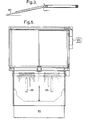
- Fig. 3 is a side elevation of the embodiment of Fig. 1 with the first and second ramps deployed;
- Fig. 4 is a side elevation of the embodiment of Fig. 1 with the face pivoted;
- Fig. 5 is a top plan of the embodiment of Fig. 1 with first and second ramps deployed;
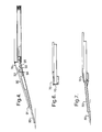
- Fig. 6 is a side elevation of a second embodiment in a retracted configuration;
- Fig. 7 is a side elevation of a second embodiment in an extended configuration;
- Fig. 8 is an enlarged partially cutaway side view of the embodiment of Fig. 6 in an extended configuration; and
- Fig. 9 is an enlarged partial side view of the embodiment of Fig. 8 in a retracted configuration.
- The illustrated embodiment is primarily intended for fitment to a low floor bus.
-
Cassette 1 is provided for a mounting of operative components of the ramp. The ramp can be supplied to vehicle builders for inclusion in the vehicle at an early stage of construction or retrofitted to an existing vehicle. -
Cassette 1 is secured to the vehicle for example by screw threaded fasteners withedge 2 about flush with the vehicle side. -
Motor 10 is provided. In the illustrated embodiment this motor is a low voltage dc motor. It will be apparent to the skilled however that other motors, such as air and hydraulic motors could be provided. -
Drive shaft 11 ofmotor 10 is provided with abevel gear 12. Second drive shaft 13 is mounted for rotation inbearings 14. Drive shaft 13 provided with a plurality of bevel gears, 15, 16, 17.Second bevel gear 15 is in meshing engagement withbevel gear 12 such that actuation ofmotor 10 causes second drive sheet 13 to rotate. - First and
second lead screws 20, 21 are provided about perpendicular to second drive shaft 13.Lead screws 20, 21 are each provided with a bevel gear 22, 23.Third bevel gear 16 of second drive shaft 13 is in meshing engagement with fifth bevel gear 22 of first lead screw 20. -
Fourth bevel gear 17 of second drive shaft is in meshing engagement with sixth bevel gear of second lead screw. - A first feed nut 30 is in meshing engagement with first lead screw 20 and second feed nut 31 is in meshing engagement with
second lead screw 21. Linkingmember 32 extends between first and second feed nuts 30, 31. - Actuation of
motor 10 thus causes linkingmember 32 to move in direction of arrow A. - Those skilled in the art will have little difficulty in devising other ways of providing a linearly movable linking
member 32. - In preferred embodiments of the invention the end of one or both feed screw is provided with a
dog 33. Engagement ofdog 33 with a tool allows linking member to be moved in the event of failure of actuatingmotor 10. This is useful in emergencies for example ifmotor 10 fails. The shape ofdog 33 is not critical for the purposes of the invention. Slots engagable by bladed tools or male or female squares or hexagons can be used. In some cases it is desirable to use a standard square for example corresponding to the drive shaft of a torque or ratchet wrench. However when used in public service vehicles with a roster of drivers the tool may be subject to loss by petty theft. To reduce the likelihood of this a dog of special shape with a tool of corresponding shape can be provided. - Hinge 40 is provided on the edge of linking
member 32 nearer the edge. In the illustrated this comprises a strip of flexible polyurethane. Those skilled in the art will have no difficulty in devising other hinges. -
First ramp 50 is hingably mounted of linkingmember 32 by hingedmember 40. Actuation ofmotor 10 thus causesfirst ramp 50 to be extended or retracted. - A position sensor for sensing the position of
ramp 50 is provided. In the illustrated embodiment the position sensor comprisesmicroswitches 60, 61 adjacent the lead screws toward the ends of the lead screws. As the ramp is extended or retracted to the limit of normaloperation linking member 32 or feed nuts actuate the microswitches. Acontrol unit 65 can then switch offmotor 10 and, as will be apparent hereafter control other features of the invention. - In some embodiments of the
invention control unit 65 monitors the current drawn bymotor 10. If movement of the ramp is inhibited for example by contacting aperson motor 10 draws a higher current. The control unit senses this and if the current exceeds a predeterminedvalue control unit 65 either switches off or reversesmotor 10. - Those skilled in the art will have little difficulty in devising suitable control units. A preferred system uses the multiplexing scheme described in US 4 907 222. By way of
example control unit 65 may comprise an Intellitec PMC CPU 98A and two Intellitec PMC I/O Modules. -
Edge 2 of thecassette 1 is provided with a resilientlybiased flap 70. The resilient bias urges the flap to closeslot 71 through which thefirst ramp 50 can be projected bymotor 10.Flap 70 serves a number of purposes.Flap 70 improves the aesthetic appearance of the vehicle.Flap 70 reduces the amount of dirt and water entering the cassette.Flap 70 reduces the height of the step between the platform of the vehicle and the ramp. - The top surface of
ramp 50 is generally provided with a ribbed surface or other textured surface which may be resilient to improve traction of people and vehicles such as wheelchairs ascending or descending theramp 50.Second ramp 80 is received in thefirst ramp 50 when the ramp as a whole is retracted.Second ramp 80 is slidably movable relative to the first ramp. In the illustrated embodiment this is achieved by providing slide guides 81 at the edges of the first in which are received the edges of second ramp. - In the illustrated embodiment
second ramp 80 is actuated by apneumatic ram 81. It will be appreciated however that other ways of actuating the ramp can be used examples include hydraulic rams and electric motors. In response to a command fromcontrol unit 65,ram 81 is actuated. In general the first ram will be partially extended at this point. It will be understood however that this is primarily a matter of convenience. - Desirably
second ramp 80 is retractable in the event that it contacts an obstruction. In the illustratedembodiment ram 81 is mounted resiliently on the first ramp.Resilient bias 85 urges ram 81 away from microswitch orother actuator 86. The bias is sufficiently strong that actuation of theram 81 does not causeram 81 to actuateactuator 86 unless the ramp meets an obstruction. In a similar manner to that describedhereinbefore control unit 65 can then causeram 81 to stop or retract. -
Face 90 offirst ramp 50 is pivotally mounted on theramp 50 toward theouter edge 91. The underside offace 90 is provided with afirst wedge 92.Second wedge 93 is provided on the ramp. Faces 94, 95 of the first and second wedges abut. The first and second wedges are relatively movable. In the illustrated embodimentsecond wedge 93 is movable. Movement of the wedges in a first direction urges theface 90 upwardly. This provides a more even ramp than would otherwise be the case. In the illustrated embodiment second wedge is actuated by a secondpneumatic ram 98 controlled bycontrol unit 65. Those skilled in the art will have little difficulty in devising other suitable ways of actuating the second wedge such as electric motors or hydraulic cylinders. Preferably, as is shown the illustrated embodiment, aresilient bias 99 is provided urging the second ram to a position in which the face is not raised. In this arrangement if supply of air to the ram failsface 90 will retract allowing the ramp to be stowed. It will be apparent that it is important forface 90 not to be pivoted until its free edge is sufficiently advanced for it not to fail. Similarly the face should be allowed to retract before second ramp is withdrawn. Those skilled in the art will have no difficulty in devising suitable ways in which controlunit 65 can ensure that this is the case. - In some embodiments of the
invention face 90 is not pivotally movable. - Figs. 6 to 9 illustrate an embodiment of this kind.
Face 90 is not pivotally mounted and consequently second pneumatic ram resilient bias and first and second wedges are not provided. -
Flap 70 is provided withnose 100. Acam track 101 is provided towards the end of the first ramp.Nose 100 of theflap 70 engagescam track 101. Asecond flap 110 is also provided. Second flap is resiliently mounted on the bottom of the first ramp. A resilient bias urges the second flap in the direction of arrow B to close the slot through which the second ramp extends. Thefree tip 102 engagesnose 100. In the closed configuration the arrangement is as shown in Fig. As the first ramp extends the resilient bias of the first and second flaps is overcome. Thefirst ramp 50 descends the cam track and abuts the top surface of the ramp providing a relatively obstruction free surface and second flap is urged outwardly. Fig. 8 shows the ramp extended. As the ramp is retracted the ends of the ramps move in board of the tip of the second flap. The resilient bias causes the flap to rotate in the direction of arrow B. The first ramp is moved upwardly as the nose engage the cam track. This allows the second flap to rotate fully home before the resilient bias urges the first flap into the position shown in Fig. 9. - In some embodiments of the invention a hole is provided near the front edge of the second ramp. A tool can be provided having an arm receivable in the hole. This allows the second ramp to be deployed or stowed manually if desired.
- In some embodiments sensors are provided to sense the condition of one or more of the handbrake, the speed of the vehicle and the vehicle doors. The
control unit 65 can monitor the sensor or sensors and for example can prevent actuation of the ramp until the handbrake is on and the vehicle speed is less than a predetermined speed for example 5kmh-1. - In an embodiment of the invention the control unit prevents deployment of the ramp unless the vehicle is moving at less than 5kmh-1, the handbrake is on and the doors are closed.
- To deploy the ramp a deployment switch is pressed and held until the ramp is fully deployed. Release of the deployment switch causes the control unit to retract the ramp. When the ramp is fully extended the deployment switch can be released and the doors opened. The control unit may actuate a ramp extended warning indicator. A warning signal for example visual and/or audible may be given during deployment.
- To retract the ramp the control unit monitors the handbrake and the doors. Retraction can not be performed unless the doors are shut and the handbrake is on. Redeployment can be prevented until a time delay for example 10 seconds has expired.
- A number of ways of reducing the likelihood of the vehicle being driven while the ramp is extended can be provided. They can include one or more of a warning signal for example visual and/or audible, the control unit could actuate the vehicle's brakes such as the handbrake could prevent engagement of the vehicle drive and/or could prevent an engine speed from being increased above a particular level.
- In some embodiments of the invention the vehicle must be stationary before the ramp can be deployed.
- Other ways of detecting an obstruction either alone or in combination with these previously described can be used. An example is providing a resettable fuse for example one employing positive temperature coefficient materials. When the motor draws too high a current for example following contact with an obstruction the fuse trips. This prevents the motor from working. The control unit monitors the fuse tripping and when power is restored retracts the ramp. A further example provides a member carried by the ramp on a resilient portion of the ramp such that if the ramp abuts an obstruction the member moves relative to other parts of the movable ramp. Abutment causes the member to actuate a switch stop or reversing the ramp. A still further example transposes the position of the switch and member.
Claims (8)
- An extendible ramp comprising:i) a chassis (1);ii) a first ramp (50) slidable movable relative to the chassis and hingable connected to the chassis (1);iii) a second ramp (80) carried by the first ramp (50) and movable relative to the chassis (1) and the first ramp (50);iv) means (10, 20, 21, 30, 31, 32) for extending and retracting the first ramp (50);v) means (81) for extending and retracting the second ramp (80);vi) means for detecting whether the ramp (50, 80) abuts an obstruction when the ramp is being extended; andvii) means for retracting the ramp (50, 80) if it abuts an obstruction during extension.
- A ramp as claimed in claim 1 wherein the first ramp (50) is hingably connected to a linking member (32) movable relative to the chassis (1).
- A ramp as claimed in claim 1 or claim 2 wherein means for moving a ramp (50) comprises at least one rotatable leadscrew (20; 21) received in a feed nut (30; 31).
- A ramp as claimed in claim 1 wherein a ramp lead screw (20; 21) is driven by an electric motor (10), comprising means for monitoring the current drawn by the motor (10) and means for stopping or reversing the motor (10) if the current drawn exceeds a predetermined value.
- A ramp as claimed in any one of the preceding claims wherein the means (81) for extending a ramp (80) are resiliently biased away from a switch (86) such that when load on the extending means (81) exceeds a predetermined value the switch (86) is actuated actuating means for stopping or retracting the ramp (80).
- A ramp as claimed in any one of the preceding claims wherein the second ramp (80) is slidable receivable within the first ramp (50).
- A ramp as claimed in any one of the preceding claims wherein the top face (90) of the first ramp (50) is pivotable.
- A ramp as claimed in claim 7 wherein means (92, 93) for urging the face (90) to a pivoted position and a bias (99) urging the face (90) away from the pivoted position are provided .
Applications Claiming Priority (3)
| Application Number | Priority Date | Filing Date | Title |
|---|---|---|---|
| GBGB9821674.0A GB9821674D0 (en) | 1998-10-05 | 1998-10-05 | Ramp |
| GB9821674 | 1998-10-05 | ||
| PCT/GB1999/003282 WO2000020252A1 (en) | 1998-10-05 | 1999-10-05 | Ramp |
Publications (2)
| Publication Number | Publication Date |
|---|---|
| EP1034088A1 EP1034088A1 (en) | 2000-09-13 |
| EP1034088B1 true EP1034088B1 (en) | 2006-06-14 |
Family
ID=10840018
Family Applications (1)
| Application Number | Title | Priority Date | Filing Date |
|---|---|---|---|
| EP99947746A Expired - Lifetime EP1034088B1 (en) | 1998-10-05 | 1999-10-05 | Ramp |
Country Status (8)
| Country | Link |
|---|---|
| US (1) | US6598253B1 (en) |
| EP (1) | EP1034088B1 (en) |
| AT (1) | ATE329789T1 (en) |
| AU (1) | AU6111899A (en) |
| CA (1) | CA2309198C (en) |
| DE (1) | DE69931887D1 (en) |
| GB (1) | GB9821674D0 (en) |
| WO (1) | WO2000020252A1 (en) |
Cited By (2)
| Publication number | Priority date | Publication date | Assignee | Title |
|---|---|---|---|---|
| DE102017126948A1 (en) | 2017-11-16 | 2019-05-16 | Knorr-Bremse Gesellschaft Mit Beschränkter Haftung | Footrest device for a sliding entry entry system for a vehicle and a sliding step entry system with a footrest device |
| EP4450357B1 (en) * | 2023-03-15 | 2025-12-24 | Bode - Die Tür GmbH | Telescopic guiding system for retractable step |
Families Citing this family (31)
| Publication number | Priority date | Publication date | Assignee | Title |
|---|---|---|---|---|
| FR2811223B1 (en) * | 2000-07-05 | 2003-01-03 | Metalic | MOTORIZED TELESCOPIC ACCESS RAMP FOR PUBLIC TRANSPORT VEHICLES |
| GB0100514D0 (en) * | 2001-01-09 | 2001-02-21 | Truck Align Company Ltd | Ramp asembly |
| US7011351B1 (en) | 2003-02-05 | 2006-03-14 | Alfa Leisure, Inc. | Slide-out lifting/lowering system for recreational vehicles |
| US7066517B1 (en) * | 2003-02-05 | 2006-06-27 | Alfa Leisure, Inc. | Moveable floor section for lifting and lowering slide-outs |
| US7066528B1 (en) | 2003-02-05 | 2006-06-27 | Alfa Leisure, Inc. | Slide-out lifting and lowering mechanism |
| ATE329790T1 (en) * | 2003-04-22 | 2006-07-15 | Zeppenfeld Ind Verwaltungs Gmb | TREAD PLATE ARRANGEMENT |
| WO2005108161A1 (en) * | 2004-05-10 | 2005-11-17 | Kevin John Fullerton | Bridging device |
| US20070006816A1 (en) * | 2005-05-04 | 2007-01-11 | Dan Dietz | Multiple function animal training system with extendable ramp |
| US20060249087A1 (en) * | 2005-05-04 | 2006-11-09 | Dietz Dan L | Multiple function animal training system with extendable ramp |
| US8926254B2 (en) * | 2005-11-08 | 2015-01-06 | Mobility Ventures Llc | Automotive vehicle having a power-actuated ramp |
| ITPA20060016A1 (en) | 2006-04-13 | 2007-10-14 | Cambiocasa S R L | FLOOR WITH RAMP FOR SMALL AND MEDIUM TRUCKS FOR UNLOADING AND LOADING OF MATERIALS OR FOR OVERCOMING ARCHITECTURAL BARRIERS. |
| FR2901823B1 (en) * | 2006-06-01 | 2010-05-07 | Myd L | DEVICE FOR AIDING THE CROSSING OF A MARKET |
| US7618085B1 (en) * | 2007-01-12 | 2009-11-17 | Gary Bean | Fifth wheel trailer housing boat and living quarters |
| NL1033716C2 (en) * | 2007-04-18 | 2008-10-21 | Pieter John Van Mullekom | Lift device for a vehicle. |
| GB2455764A (en) * | 2007-12-20 | 2009-06-24 | Truck Align Company Ltd | Manually-deployable access ramp assembly |
| FR2931406B1 (en) * | 2008-05-21 | 2010-11-19 | Metalic | SAFETY DEVICE FOR A PUBLIC TRANSPORT VEHICLE ACCESS RAMP HOUSING |
| CN101554873B (en) * | 2009-03-20 | 2010-12-08 | 徐善慧 | Double-layer or multi-layer scalable foot-miss prevention plate Mechanism for removing clearance between rail transit carriage and platform |
| GB2499421B (en) | 2012-02-15 | 2014-03-26 | Truck Align Company Ltd | Ramp |
| US9101519B2 (en) * | 2013-02-07 | 2015-08-11 | Dallas Smith Corporation | Leveling ramp for a wheelchair |
| US8869333B2 (en) * | 2013-03-01 | 2014-10-28 | Lift-U, Division Of Hogan Mfg., Inc. | Ramp assembly with tilt sensor |
| US8745800B1 (en) * | 2013-07-16 | 2014-06-10 | Lift-U, Division Of Hogan Mfg., Inc. | Fold out ramp |
| FR3020081B1 (en) * | 2014-04-22 | 2016-05-06 | Myd L | DEVICE FOR ASSISTING THE FRACTURE OF AN OBSTACLE BY A VEHICLE |
| US20160144759A1 (en) * | 2014-11-24 | 2016-05-26 | Magna Closures Inc. | Tailgate ramp apparatus |
| WO2016120798A1 (en) * | 2015-01-28 | 2016-08-04 | Douglas Marine S.R.L. | Climbing system with telescopic ramp or ladder, in particular for boats or the like |
| US10919428B2 (en) * | 2015-08-07 | 2021-02-16 | Ford Global Technologies, Llc | Powered sliding platform assembly |
| GB2552509A (en) * | 2016-07-26 | 2018-01-31 | Truck Align London Ltd | Lead screw mechanism |
| SG10201705966SA (en) * | 2017-07-20 | 2019-02-27 | Nicae Singapore Pte Ltd | Automatic Ramp |
| EP3542768A1 (en) * | 2018-03-21 | 2019-09-25 | Masats, S.A. | Retractable ramp assembly for people to access vehicles |
| AU2019236731B1 (en) * | 2019-09-26 | 2020-08-20 | The Trustee For Rofraus Trust | Ascending mechanised access ramp (a-mar) |
| US12403052B2 (en) | 2021-06-28 | 2025-09-02 | The Braun Corporation | Ramp siderail deployment apparatus and method |
| CN119176083B (en) * | 2024-11-25 | 2025-03-14 | 浙江中车电车有限公司 | Intelligent pedal structure, pedal control method and passenger car |
Family Cites Families (19)
| Publication number | Priority date | Publication date | Assignee | Title |
|---|---|---|---|---|
| GB2072884B (en) * | 1980-03-28 | 1985-01-16 | Hitachi Ltd | Automatic door control apparatus |
| US4533905A (en) * | 1981-05-19 | 1985-08-06 | Firmagroup Australia Pty. Ltd. | Indicating means for a door operator device |
| US4701684A (en) * | 1984-11-26 | 1987-10-20 | Automatic Roller Doors Australia Pty. Ltd. | Door or gate obstruction control |
| FR2587667B1 (en) * | 1985-09-25 | 1989-10-20 | Alsthom | DEVICE FOR PROVIDING EASY ACCESS TO RAIL VEHICLES DURING STATION STOPS |
| US4907222A (en) * | 1988-08-17 | 1990-03-06 | Nuvatec, Inc. | Vehicle multiplex system |
| DE8815693U1 (en) * | 1988-12-17 | 1989-02-23 | Gebr. Bode & Co GmbH, 3500 Kassel | Ramp for vehicles without internal steps |
| US6120234A (en) * | 1991-02-12 | 2000-09-19 | Dinverno; Daniel | Van-mounted service carts for skilled tradesmen and ramp mechanisms for use with the same |
| DE4134559C2 (en) * | 1991-10-19 | 1995-11-02 | Daimler Benz Ag | Ramp for a door entry |
| US5340267A (en) * | 1991-12-17 | 1994-08-23 | Overhead Door Corporation | Retractable vehicle ramp with lift assist |
| US6064165A (en) * | 1992-04-22 | 2000-05-16 | Nartron Corporation | Power window or panel controller |
| DE4330638C2 (en) * | 1993-09-10 | 1998-02-12 | Mbb Foerder & Hebesysteme | Device for trouble-free climbing and rolling over a ramp |
| US5331701A (en) * | 1993-09-13 | 1994-07-26 | Chase Vearl J | Vehicle chair ramp apparatus |
| GB9403572D0 (en) * | 1994-02-24 | 1994-04-13 | Unwin C N Ltds | Improvements relating to trolley transfer apparatus |
| US5636399A (en) * | 1995-02-27 | 1997-06-10 | Ricon Corporation | Movable ramp assembly |
| US5832555A (en) * | 1995-02-27 | 1998-11-10 | Ricon Corporation | Compact moveable ramp assembly |
| GB9522368D0 (en) * | 1995-11-01 | 1996-01-03 | Taurus Bodies | Vehicle access ramps |
| US5676515A (en) * | 1996-06-03 | 1997-10-14 | Haustein; Norman E. | Low floor vehicle ramp |
| US5775232A (en) * | 1997-02-14 | 1998-07-07 | Vapor Corporation | Bridge plate for a mass transit vehicle |
| US6118243A (en) * | 1999-04-07 | 2000-09-12 | Overhead Door Corporation | Door operator system |
-
1998
- 1998-10-05 GB GBGB9821674.0A patent/GB9821674D0/en not_active Ceased
-
1999
- 1999-10-05 AU AU61118/99A patent/AU6111899A/en not_active Abandoned
- 1999-10-05 DE DE69931887T patent/DE69931887D1/en not_active Expired - Lifetime
- 1999-10-05 US US09/530,613 patent/US6598253B1/en not_active Expired - Fee Related
- 1999-10-05 WO PCT/GB1999/003282 patent/WO2000020252A1/en not_active Ceased
- 1999-10-05 CA CA002309198A patent/CA2309198C/en not_active Expired - Fee Related
- 1999-10-05 AT AT99947746T patent/ATE329789T1/en not_active IP Right Cessation
- 1999-10-05 EP EP99947746A patent/EP1034088B1/en not_active Expired - Lifetime
Cited By (3)
| Publication number | Priority date | Publication date | Assignee | Title |
|---|---|---|---|---|
| DE102017126948A1 (en) | 2017-11-16 | 2019-05-16 | Knorr-Bremse Gesellschaft Mit Beschränkter Haftung | Footrest device for a sliding entry entry system for a vehicle and a sliding step entry system with a footrest device |
| WO2019096927A1 (en) | 2017-11-16 | 2019-05-23 | Knorr-Bremse Gesellschaft Mit Beschränkter Haftung | Tread device for a retractable step access system for a vehicle, and retractable step access system with a tread device |
| EP4450357B1 (en) * | 2023-03-15 | 2025-12-24 | Bode - Die Tür GmbH | Telescopic guiding system for retractable step |
Also Published As
| Publication number | Publication date |
|---|---|
| GB9821674D0 (en) | 1998-12-02 |
| EP1034088A1 (en) | 2000-09-13 |
| ATE329789T1 (en) | 2006-07-15 |
| CA2309198A1 (en) | 2000-04-13 |
| WO2000020252A1 (en) | 2000-04-13 |
| CA2309198C (en) | 2005-06-21 |
| AU6111899A (en) | 2000-04-26 |
| US6598253B1 (en) | 2003-07-29 |
| DE69931887D1 (en) | 2006-07-27 |
| HK1031853A1 (en) | 2001-06-29 |
Similar Documents
| Publication | Publication Date | Title |
|---|---|---|
| US6598253B1 (en) | Extendable ramp assembly for detecting an obstruction and responding thereto | |
| US6186733B1 (en) | Low floor vehicle ramp assembly | |
| US4988254A (en) | Vehicle restraint | |
| US5071306A (en) | Vehicle restraint | |
| US4493603A (en) | Wheel chair lift apparatus | |
| US8122553B1 (en) | Fold out ramp | |
| US9271883B2 (en) | Ramp assembly with tilt sensor | |
| US6676360B2 (en) | Vehicle restraining device | |
| US4420286A (en) | Invalid lift apparatus | |
| US20150052693A1 (en) | Ramp | |
| US4708355A (en) | Hideaway vehicle step | |
| US20060245883A1 (en) | Vehicle ramp assembly | |
| US20030007853A1 (en) | Low floor vehicle ramp assembly | |
| US9937933B2 (en) | High level platform trapdoor with built in moving slide for railway platform gap bridging | |
| US4559659A (en) | Power operated wheelchair ramp | |
| US9546056B2 (en) | Dock leveler safety supports | |
| US5165839A (en) | Wheelchair lift for railway cars | |
| US6139242A (en) | Vehicle restraint with security device | |
| US7033127B2 (en) | Powered, folding ramp for minivan | |
| HK1031853B (en) | Ramp | |
| JP3169472B2 (en) | Automatic opening and closing control device for work vehicle windows | |
| CN210710254U (en) | Telescopic foot protection plate | |
| JPH01106743A (en) | Car tail lift | |
| US20050077111A1 (en) | Threshold switch apparatus for a mobility access device |
Legal Events
| Date | Code | Title | Description |
|---|---|---|---|
| PUAI | Public reference made under article 153(3) epc to a published international application that has entered the european phase |
Free format text: ORIGINAL CODE: 0009012 |
|
| AK | Designated contracting states |
Kind code of ref document: A1 Designated state(s): AT BE CH CY DE DK ES FI FR GB GR IE IT LI LU MC NL PT SE |
|
| AX | Request for extension of the european patent |
Free format text: AL;LT;LV;MK;RO;SI |
|
| 17P | Request for examination filed |
Effective date: 20001005 |
|
| GRAP | Despatch of communication of intention to grant a patent |
Free format text: ORIGINAL CODE: EPIDOSNIGR1 |
|
| GRAS | Grant fee paid |
Free format text: ORIGINAL CODE: EPIDOSNIGR3 |
|
| GRAA | (expected) grant |
Free format text: ORIGINAL CODE: 0009210 |
|
| AK | Designated contracting states |
Kind code of ref document: B1 Designated state(s): AT BE CH CY DE DK ES FI FR GB GR IE IT LI LU MC NL PT SE |
|
| PG25 | Lapsed in a contracting state [announced via postgrant information from national office to epo] |
Ref country code: NL Free format text: LAPSE BECAUSE OF FAILURE TO SUBMIT A TRANSLATION OF THE DESCRIPTION OR TO PAY THE FEE WITHIN THE PRESCRIBED TIME-LIMIT Effective date: 20060614 Ref country code: LI Free format text: LAPSE BECAUSE OF FAILURE TO SUBMIT A TRANSLATION OF THE DESCRIPTION OR TO PAY THE FEE WITHIN THE PRESCRIBED TIME-LIMIT Effective date: 20060614 Ref country code: IT Free format text: LAPSE BECAUSE OF FAILURE TO SUBMIT A TRANSLATION OF THE DESCRIPTION OR TO PAY THE FEE WITHIN THE PRE;WARNING: LAPSES OF ITALIAN PATENTS WITH EFFECTIVE DATE BEFORE 2007 MAY HAVE OCCURRED AT ANY TIME BEFORE 2007. THE CORRECT EFFECTIVE DATE MAY BE DIFFERENT FROM THE ONE RECORDED.SCRIBED TIME-LIMIT Effective date: 20060614 Ref country code: FI Free format text: LAPSE BECAUSE OF FAILURE TO SUBMIT A TRANSLATION OF THE DESCRIPTION OR TO PAY THE FEE WITHIN THE PRESCRIBED TIME-LIMIT Effective date: 20060614 Ref country code: CH Free format text: LAPSE BECAUSE OF FAILURE TO SUBMIT A TRANSLATION OF THE DESCRIPTION OR TO PAY THE FEE WITHIN THE PRESCRIBED TIME-LIMIT Effective date: 20060614 Ref country code: BE Free format text: LAPSE BECAUSE OF FAILURE TO SUBMIT A TRANSLATION OF THE DESCRIPTION OR TO PAY THE FEE WITHIN THE PRESCRIBED TIME-LIMIT Effective date: 20060614 Ref country code: AT Free format text: LAPSE BECAUSE OF FAILURE TO SUBMIT A TRANSLATION OF THE DESCRIPTION OR TO PAY THE FEE WITHIN THE PRESCRIBED TIME-LIMIT Effective date: 20060614 |
|
| REG | Reference to a national code |
Ref country code: GB Ref legal event code: FG4D |
|
| REG | Reference to a national code |
Ref country code: CH Ref legal event code: EP |
|
| REG | Reference to a national code |
Ref country code: IE Ref legal event code: FG4D |
|
| REF | Corresponds to: |
Ref document number: 69931887 Country of ref document: DE Date of ref document: 20060727 Kind code of ref document: P |
|
| PG25 | Lapsed in a contracting state [announced via postgrant information from national office to epo] |
Ref country code: SE Free format text: LAPSE BECAUSE OF FAILURE TO SUBMIT A TRANSLATION OF THE DESCRIPTION OR TO PAY THE FEE WITHIN THE PRESCRIBED TIME-LIMIT Effective date: 20060914 Ref country code: DK Free format text: LAPSE BECAUSE OF FAILURE TO SUBMIT A TRANSLATION OF THE DESCRIPTION OR TO PAY THE FEE WITHIN THE PRESCRIBED TIME-LIMIT Effective date: 20060914 |
|
| PG25 | Lapsed in a contracting state [announced via postgrant information from national office to epo] |
Ref country code: DE Free format text: LAPSE BECAUSE OF FAILURE TO SUBMIT A TRANSLATION OF THE DESCRIPTION OR TO PAY THE FEE WITHIN THE PRESCRIBED TIME-LIMIT Effective date: 20060915 |
|
| PG25 | Lapsed in a contracting state [announced via postgrant information from national office to epo] |
Ref country code: ES Free format text: LAPSE BECAUSE OF FAILURE TO SUBMIT A TRANSLATION OF THE DESCRIPTION OR TO PAY THE FEE WITHIN THE PRESCRIBED TIME-LIMIT Effective date: 20060925 |
|
| PG25 | Lapsed in a contracting state [announced via postgrant information from national office to epo] |
Ref country code: IE Free format text: LAPSE BECAUSE OF NON-PAYMENT OF DUE FEES Effective date: 20061005 |
|
| PG25 | Lapsed in a contracting state [announced via postgrant information from national office to epo] |
Ref country code: MC Free format text: LAPSE BECAUSE OF NON-PAYMENT OF DUE FEES Effective date: 20061031 |
|
| PG25 | Lapsed in a contracting state [announced via postgrant information from national office to epo] |
Ref country code: PT Free format text: LAPSE BECAUSE OF FAILURE TO SUBMIT A TRANSLATION OF THE DESCRIPTION OR TO PAY THE FEE WITHIN THE PRESCRIBED TIME-LIMIT Effective date: 20061114 |
|
| NLV1 | Nl: lapsed or annulled due to failure to fulfill the requirements of art. 29p and 29m of the patents act | ||
| REG | Reference to a national code |
Ref country code: CH Ref legal event code: PL |
|
| REG | Reference to a national code |
Ref country code: HK Ref legal event code: GR Ref document number: 1031853 Country of ref document: HK |
|
| PLBE | No opposition filed within time limit |
Free format text: ORIGINAL CODE: 0009261 |
|
| STAA | Information on the status of an ep patent application or granted ep patent |
Free format text: STATUS: NO OPPOSITION FILED WITHIN TIME LIMIT |
|
| EN | Fr: translation not filed | ||
| 26N | No opposition filed |
Effective date: 20070315 |
|
| PG25 | Lapsed in a contracting state [announced via postgrant information from national office to epo] |
Ref country code: GR Free format text: LAPSE BECAUSE OF FAILURE TO SUBMIT A TRANSLATION OF THE DESCRIPTION OR TO PAY THE FEE WITHIN THE PRESCRIBED TIME-LIMIT Effective date: 20060915 Ref country code: FR Free format text: LAPSE BECAUSE OF FAILURE TO SUBMIT A TRANSLATION OF THE DESCRIPTION OR TO PAY THE FEE WITHIN THE PRESCRIBED TIME-LIMIT Effective date: 20070309 |
|
| PG25 | Lapsed in a contracting state [announced via postgrant information from national office to epo] |
Ref country code: LU Free format text: LAPSE BECAUSE OF NON-PAYMENT OF DUE FEES Effective date: 20061005 |
|
| PG25 | Lapsed in a contracting state [announced via postgrant information from national office to epo] |
Ref country code: FR Free format text: LAPSE BECAUSE OF FAILURE TO SUBMIT A TRANSLATION OF THE DESCRIPTION OR TO PAY THE FEE WITHIN THE PRESCRIBED TIME-LIMIT Effective date: 20060614 Ref country code: CY Free format text: LAPSE BECAUSE OF FAILURE TO SUBMIT A TRANSLATION OF THE DESCRIPTION OR TO PAY THE FEE WITHIN THE PRESCRIBED TIME-LIMIT Effective date: 20060614 |
|
| PGFP | Annual fee paid to national office [announced via postgrant information from national office to epo] |
Ref country code: GB Payment date: 20131028 Year of fee payment: 15 |
|
| GBPC | Gb: european patent ceased through non-payment of renewal fee |
Effective date: 20141005 |
|
| PG25 | Lapsed in a contracting state [announced via postgrant information from national office to epo] |
Ref country code: GB Free format text: LAPSE BECAUSE OF NON-PAYMENT OF DUE FEES Effective date: 20141005 |