EP1033939B1 - Device for installing a tissue fastener - Google Patents
Device for installing a tissue fastener Download PDFInfo
- Publication number
- EP1033939B1 EP1033939B1 EP98962393A EP98962393A EP1033939B1 EP 1033939 B1 EP1033939 B1 EP 1033939B1 EP 98962393 A EP98962393 A EP 98962393A EP 98962393 A EP98962393 A EP 98962393A EP 1033939 B1 EP1033939 B1 EP 1033939B1
- Authority
- EP
- European Patent Office
- Prior art keywords
- conduit
- magazine
- fastener
- fasteners
- tissue
- Prior art date
- Legal status (The legal status is an assumption and is not a legal conclusion. Google has not performed a legal analysis and makes no representation as to the accuracy of the status listed.)
- Expired - Lifetime
Links
- 238000003780 insertion Methods 0.000 claims description 17
- 230000037431 insertion Effects 0.000 claims description 17
- 239000003381 stabilizer Substances 0.000 claims 1
- 230000007246 mechanism Effects 0.000 description 13
- 238000000034 method Methods 0.000 description 12
- 238000001356 surgical procedure Methods 0.000 description 7
- 239000007943 implant Substances 0.000 description 6
- 230000005499 meniscus Effects 0.000 description 5
- 238000007373 indentation Methods 0.000 description 4
- 230000007794 irritation Effects 0.000 description 3
- 210000003127 knee Anatomy 0.000 description 3
- 230000008439 repair process Effects 0.000 description 3
- 206010061218 Inflammation Diseases 0.000 description 2
- 230000001133 acceleration Effects 0.000 description 2
- 230000008901 benefit Effects 0.000 description 2
- 230000004054 inflammatory process Effects 0.000 description 2
- 238000013459 approach Methods 0.000 description 1
- 230000008859 change Effects 0.000 description 1
- -1 combustive Substances 0.000 description 1
- 238000011161 development Methods 0.000 description 1
- 239000002360 explosive Substances 0.000 description 1
- 208000015181 infectious disease Diseases 0.000 description 1
- 208000014674 injury Diseases 0.000 description 1
- 238000012986 modification Methods 0.000 description 1
- 230000004048 modification Effects 0.000 description 1
- 210000005036 nerve Anatomy 0.000 description 1
- 230000008569 process Effects 0.000 description 1
- 230000011664 signaling Effects 0.000 description 1
- 239000000126 substance Substances 0.000 description 1
- 238000012360 testing method Methods 0.000 description 1
- 230000008733 trauma Effects 0.000 description 1
Images



Classifications
-
- A—HUMAN NECESSITIES
- A61—MEDICAL OR VETERINARY SCIENCE; HYGIENE
- A61B—DIAGNOSIS; SURGERY; IDENTIFICATION
- A61B17/00—Surgical instruments, devices or methods
- A61B17/064—Surgical staples, i.e. penetrating the tissue
-
- A—HUMAN NECESSITIES
- A61—MEDICAL OR VETERINARY SCIENCE; HYGIENE
- A61B—DIAGNOSIS; SURGERY; IDENTIFICATION
- A61B17/00—Surgical instruments, devices or methods
- A61B17/068—Surgical staplers, e.g. containing multiple staples or clamps
-
- A—HUMAN NECESSITIES
- A61—MEDICAL OR VETERINARY SCIENCE; HYGIENE
- A61B—DIAGNOSIS; SURGERY; IDENTIFICATION
- A61B17/00—Surgical instruments, devices or methods
- A61B17/10—Surgical instruments, devices or methods for applying or removing wound clamps, e.g. containing only one clamp or staple; Wound clamp magazines
- A61B17/105—Wound clamp magazines
-
- A—HUMAN NECESSITIES
- A61—MEDICAL OR VETERINARY SCIENCE; HYGIENE
- A61B—DIAGNOSIS; SURGERY; IDENTIFICATION
- A61B17/00—Surgical instruments, devices or methods
- A61B17/12—Surgical instruments, devices or methods for ligaturing or otherwise compressing tubular parts of the body, e.g. blood vessels or umbilical cord
- A61B17/122—Clamps or clips, e.g. for the umbilical cord
- A61B17/1222—Packages or dispensers therefor
-
- A—HUMAN NECESSITIES
- A61—MEDICAL OR VETERINARY SCIENCE; HYGIENE
- A61B—DIAGNOSIS; SURGERY; IDENTIFICATION
- A61B17/00—Surgical instruments, devices or methods
- A61B17/064—Surgical staples, i.e. penetrating the tissue
- A61B2017/0646—Surgical staples, i.e. penetrating the tissue for insertion into cartillege, e.g. meniscus
Definitions
- This invention relates to the field of surgical devices. More specifically, this invention relates to an improved surgical device for inserting tissue fasteners.
- the surgical device of the invention is particularly but not solely intended to be used in repair surgery of traumas of soft and/or tough tissues containing fibrous structures, such as knee meniscal tissues.
- Tissue fasteners have been developed, including fasteners that may be inserted entirely below the surface of the tissue that is being treated, thereby preventing any irritation that may result from the portion of the fastener remaining above the ruptured tissue surface. These fasteners are described in detail in WO 99/01071, entitled SURGICAL FASTENER FOR TISSUE TREATMENT, by Tormala, et al.
- United States Patent No. 5,569,264 describes a device for inserting implants into a patient that can hold more than one implant in a cassette or box.
- the box sits on top of the frame of the device and pushes implants from the box into the frame and into the channel through which the implants are inserted.
- the magazine must be filled with a suitable number of implants in advance of the operation.
- the surgeon will not always know how many implants are needed for a particular operation.
- none of these devices provide a method for inserting fasteners in such a way that no part of the fastener remains on or above the surface of the tissue being treated. It is advantageous to be able to insert fasteners entirely below the surface of the tissue being treated to avoid any irritation or inflammation that could occur when other tissues rub against that portion of the fastener on or above the tissue that has been treated.
- tissue fasteners that is capable of holding more than one fastener and capable of receiving additional fasteners during an operation without requiring the surgeon to remove the device from the patient.
- the surgeon may use as many fasteners as he requires, while only having to insert the device into the patient once. Also, no fasteners are wasted. This reduces the length, difficulty, and cost of the procedure.
- a device that is capable of inserting a fastener entirely within the tissue to be treated so that no part of the fastener remains above or on the surface of the tissue. Such a device reduces the likelihood of irritation and inflammation of the treated area.
- tissue fasteners that allows a minimally invasive method for repairing torn or ruptured tissue.
- the device of the present invention is designed for repairing a tear in soft and/or tough tissue of a patient, such as a tear in the meniscus of the knee.
- the device has a conduit, such as a cannula, that may be easily inserted into the patient and through which the fastener is delivered to the patient.
- This conduit is aligned with a seat for holding a fastener and a means for pushing a fastener, such as a piston, so that the pushing means is capable of pushing a fastener from its seat, through the conduit and into the patient.
- the shape of the conduit exactly matches the shape of the cross-section of the fastener so that the surgeon may more accurately direct the angle and location at which the fastener enters the patient.
- the pushing means may be made to slowly push the fastener from its seat and through the conduit until the distal end of the fastener contacts the surface of the tissue to be treated at the end of the conduit. At that time, the pushing means may be made to accelerate rapidly, thereby inserting the fastener into the tissue being treated.
- the seat for holding fasteners is capable of holding a magazine containing one or more fasteners.
- the magazine When inserted into the seat, the magazine may be positioned so that a fastener is aligned with the pushing means and the conduit leading to the patient. Once a fastener has been inserted into the patient, the magazine may be manually positioned so that another fastener is shifted into position to be inserted.
- the magazine may have means, such as a spring, for automatically moving a fastener into position for insertion once a fastener has been inserted.
- the magazine may be easily removed from the seat during an operation, so that it may be replaced with a magazine containing one or more fasteners without requiring the conduit to be removed from the patient. Also, the same magazine can be removed, refilled with one or more additional fasteners, and reinserted into the seat, without requiring the removal of the conduit from the patient.
- a portion of the magazine is accessible to allow the insertion of one or more additional fasteners into the magazine. In this fashion, additional fasteners may be added to the magazine without requiring its removal from the device or the removal of the conduit of the device from the patient.
- the conduit or barrel of the device is easily removable from the rest of the device. This allows the same device to be used during an operation with differently shaped conduits, depending upon the location and condition of the tissue being treated. Thus, for instance, during the same operation, the surgeon could insert fasteners through a straight conduit, then easily replace the straight conduit with a curved conduit and continue the operation without the need for an entirely new device.
- the pushing means e.g., piston
- the pushing means is capable of extending slightly beyond the end of the conduit that is in contact with the tissue being treated. Such extension of the pushing means ensures that it pushes the fastener until it is embedded entirely within the tissue being treated, with no portion of the fastener remaining on or above the surface of the tissue being treated.
- the device has a safety mechanism that helps prevent the surgeon from inadvertently shooting the fastener into the patient until the proper moment.
- This mechanism works in conjunction with the triggering mechanism so that the means for propelling the pushing means rapidly into the fastener cannot be actuated until both the triggering means and the safety mechanism are actuated simultaneously.
- the present invention comprises a conduit 2, containing an internal channel, 2a, through which a fastener may be pushed.
- the conduit 2 terminates distally at end 2b, which is where the fastener exits the conduit 2 and is inserted into the tissue being treated.
- end 2b is placed in contact with the tissue to be treated.
- the end 2b is not perpendicular to the conduit 2, but rather is angled to provide better contact with the tissue to be treated.
- the end 2b can be smooth, or can be rough or contain points or other means that oppose the movement of the end 2b laterally across the surface of the tissue to be treated.
- Such points or other corresponding structures at end 2b stabilize the end 2b by preventing it from inadvertently slipping across the tissue being treated once the surgeon has properly positioned the end 2b of the conduit 2 in contact with the tissue where the fastener is to be inserted.
- the points or corresponding structure at the end 2b of the conduit 2 are retractable, thereby allowing easy movement of the end 2b of the conduit 2 within the patient when retracted, yet preventing slippage of the end 2b of the conduit 2 when extended.
- a surgeon could have the points retracted while positioning the end 2b of the conduit 2 within the patient, and then extend the points once he has properly positioned the end 2 of the conduit 2b within the patient and is ready to insert the fastener.
- conduit 2 The geometry of the conduit 2 is variable, and will depend upon the type and location of the tissue being treated.
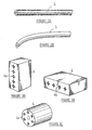
- Figure 2 demonstrates in side view two possible geometries for conduit 2.
- the conduit 2 will have an elongated shape and a cross section that may vary depending upon the type and location of tissue to be treated.
- the conduit may have a circular or ellipsoidal cross section.
- the conduit 2 can be straight or contain gradual curves to allow easier, less invasive positioning of the end 2b within the patient.
- the shape of the internal channel 2a is variable, and will depend upon the shape of the fastener being inserted.
- the shape of the internal channel 2a is the same as the shape of the cross section of the fastener. This allows for accurate control of the angle and location of insertion of the fastener.
- the particular internal channels in Figure 2 are for use with fasteners having a cross-shaped cross section.
- the conduit 2 is easily removable from the body 1 of the device 15.
- This enables a surgeon to conveniently replace a conduit during an operation in order to allow easier, quicker, less invasive positioning of fasteners.
- the surgeon can simply remove the straight conduit from the body of the device and replace it with a curved conduit and continue the operation. This affords the surgeon great flexibility and helps to insure that the surgery will be as quick and minimally invasive as possible, as well as cost efficient.
- the conduit 2 may be releasably attached to the body 1 at its proximal end by any of several methods that are well known for the releasable attachment of mechanical parts.
- the body 1 may contain a simple spring loaded release that, when compressed or pulled or otherwise manipulated, allows the removal and insertion of conduit 2, yet when left alone secures the conduit 2 within the body 1.
- the proximal end of conduit 2 attaches to the body 1 near the fastener magazine seat 3.
- the magazine seat is capable of receiving a magazine 4 containing one or more fasteners.
- the magazine seat 3 is configured so that the magazine 4 may be easily positioned within the magazine seat 3 so that a fastener within the magazine 4 is aligned with the entrance to the internal channel 2a of the conduit 2. Once a fastener has been inserted into a patient, the magazine 4 may again be easily positioned within the magazine seat 3 so that another fastener contained within the magazine 4 is aligned with the entrance to the internal channel 2a of the conduit 2.
- a magazine locking mechanism 16 that promotes alignment of the magazine 4 within the magazine seat 3 and ensures that, once aligned within the magazine seat 3, the magazine 4 does not inadvertently slip out of alignment.
- This magazine locking function can be achieved, for example, by a spring loaded ball bearing that slides against the side of the magazine 4 as it moves within the magazine seat 3.
- the side of the magazine 4 can contain slight indentations for receiving the spring loaded ball bearing when the magazine 4 is aligned.
- the presence of the spring loaded ball bearing in the indentation provides enough resistance to movement to prevent the magazine 4 from inadvertently slipping out of alignment, yet does not provide so much resistance that the surgeon cannot slide the magazine 4 within the magazine seat 3 to move another fastener into alignment.
- the ball bearing slides out of the indentation and slides along the side of magazine 4 until it enters another indentation, signaling to the surgeon that the magazine is positioned so that another fastener is in proper alignment.
- the magazine 4 need not be manually positioned within the magazine seat 3 to align another fastener with the internal channel 2a of the conduit 2 because the magazine 4 contains means for automatically aligning another fastener once the previously-aligned fastener has been inserted.
- This means may be as simple as a spring contained within the magazine 4 that pushes the fasteners of the magazine sequentially into alignment for insertion.
- the magazine 4 and magazine seat 3 may have a variety of geometries.
- Figure 3 demonstrates some potential geometries of magazines for use with this invention.
- the magazine 4 may be box-shaped, with channels 4a for fasteners arranged linearly, either horizontally or vertically, within the magazine.
- Such box-shaped magazines may simply be pushed or pulled horizontally or vertically through or within the magazine seat in order to align a fastener for insertion.
- the magazine 4 may be cylindrically shaped, with the channels 4a for fasteners arranged circularly within the magazine 4.
- Such cylindrical magazines may simply be rotated within the magazine seat in order to align a fastener for insertion.
- the particular magazines of Figure 3 are for use with fasteners having a cross-shaped cross section, however the magazines may easily be configured to hold fasteners of various cross-sections.
- the magazine 4 when the magazine 4 is aligned within the magazine seat 3, a portion of the magazine 4 remains accessible to the surgeon or other medical personnel for the insertion of additional fasteners to the magazine 4.
- the magazine may then be positioned so that the newly-inserted fastener is aligned for insertion. By so positioning the magazine to align the fastener, another portion of the magazine will now be accessible to the surgeon for the insertion of another fastener.
- another fastener may be inserted into the magazine, without the magazine being removed from the magazine seat.
- the magazine may be positioned so that the newly-inserted fastener is aligned for insertion. Such positioning will make another portion of the magazine accessible to the surgeon for the insertion of another fastener into the magazine. In this fashion, the surgeon may continually replenish the magazine and thereby use an unlimited number of fasteners during an operation, without ever having to entirely remove the magazine from the device.
- a piston 9 serves to push the fastener from the magazine 4, through the internal channel 2a, and into the patient.
- the proximal end 9a of the piston 9 extends out from the body 1 of the device so that the piston 9 may be positioned manually.
- the piston 9 When the piston 9 is fully retracted, i.e., when the piston 9 is located as far away from the conduit 2 as possible, the distal end of the piston 9 is located proximally of the magazine seat 3, thereby allowing the magazine 4 to be positioned so that a fastener is aligned with the piston 9 and the internal channel 2a of the conduit 2.
- the piston 9 is capable of sliding through the magazine 4 in the magazine seat 3, thereby pushing the aligned fastener from the magazine 4 into the conduit 2.
- the piston 9 When fully extended, the piston 9 reaches the distal end 2b of the conduit 2 and is thereby capable of pushing the fastener from the conduit 2 into the patient.
- the piston 9 is capable of extending slightly beyond the distal end 2b of the conduit 2, thereby allowing it to push a fastener entirely within the tissue being treated, so that no part of the fastener remains above or on the tissue surface.
- the piston 9 may be accelerated in several different ways.
- the means for accelerating the piston 9 is a simple spring mechanism 7.
- Other possibilities include pneumatic, hydraulic, explosive, combustive, chemical or electromagnetic mechanisms.
- the spring 7 is attached to a striking pin 6, which is capable of traveling along a loop 5 and thereby striking and accelerating the piston 9.
- there is a safety means 14 which prevents the inadvertent acceleration of the striking pin 6 into the piston 9.
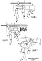
- the spring mechanism 7 which is used to accelerate the piston 9 must be cocked. This is done by pushing the cocking lever 10 towards the handle 12 of the device.
- the cocking lever 10 pivots around point 10a, thereby causing the end 10b of the cocking lever to push the striking pin 6 in the proximal direction, thereby compressing the spring 7.
- the distal end of the striking pin 6 travels along the loop 5 in the proximal direction until it is pushed by the slanted end of the safety 14 into a notch 8 at the proximal end of the loop 5. When in the notch 8, the striking pin 6 cannot move distally. Thus, the spring 7 remains compressed.
- FIG 4 shows the relative positions of the cocking lever 10, striking pin 6, piston 9, safety 14, and trigger 13 just after the striking pin has been cocked. As seen on Figure 1, the cocking lever 10 is returned to its previous position by a separate return spring 11.
- the piston 9 may be freely positioned by the surgeon.
- the surgeon pulls the piston 9 proximally, so that the distal end of the piston 9 is located proximally of the magazine seat 3.
- a magazine 4 is inserted into the magazine seat 3 and positioned so that a fastener is aligned with the internal channel 2a of the conduit 2 and the piston 9.
- the surgeon may then push the piston 9 distally, so that the distal end of the piston 9 travels through the magazine 4, thereby pushing the fastener into internal channel 2a of the conduit 2.
- the piston 9 may be pushed until the fastener reaches the distal end 2b of the conduit 2 and contacts the tissue to be treated.
- the surgeon must then release the safety 14 by pushing the safety lever 14 distally.
- the safety 14 When the safety 14 is in position A, the top end of the safety 14 holds the striking pin 6 in place in the notch 8 on the loop 5.
- the safety lever 14 When the safety lever 14 is moved distally to position B, the lever 14 pivots around point 14a, and the top of the safety lever 14 moves proximally and downward, thereby no longer preventing the striking pin 6 from moving distally and upward when moved out of the notch 8 on the loop 5 by the triggering means 13.
- the surgeon While holding the safety lever in position B, the surgeon then pulls the trigger 13 proximally, from position C to position D as shown in Figure 5.
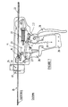
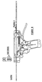
- Figures 7 through 10 depict another preferred embodiment of the invention and its method of operation.
- the device is cocked by pressing the cocking lever 19 forward against the hand grip 28, so that the cocking mechanism 29 cocks the striking pin 23, by pushing the striking pin 23 against the spring 20 and compressing it.
- the safety mechanism 27 automatically locks the trigger 26 in place and a separate return spring 21 returns the cocking lever 19 to its original position (as in Figure 8).
- the device is loaded by manually pulling the piston 22 back to the I position ( see Figure 8), placing a cartridge magazine 24 in the cartridge magazine seat 17, and fastening that magazine in place with the locking mechanism 18.
- the piston 22 is then pushed forward so the tip of the piston passes through the cartridge magazine, thereby moving a fastener into the canule tube 25, about 20 mm from the tip of the canule.
- the tip of the canule 25 is placed firmly against the torn meniscus so that the edges of the meniscus are pressed against each other, the safety mechanism of the device is released by pushing the safety lever 27 from position E to position F (see Figures 9 and 10), and the device is fired by pulling the trigger 26 from position G to position H ( see Figures 9 and 10).
- the device can be fired only if the safety lever is in position F. Pulling the trigger 26 in this manner releases the striking pin 23, which is then moved forward by the energy of the spring 20, as it decompresses.
- the striking pin 23 moves forward in the loop 15, which also moves the piston 22 forward by way of a notch 16.
- the tip of the piston 22 then pushes the fastener into the meniscus, while the tip of the piston stops at the end of the canule 25.
- the entire procedure can be repeated by cocking the spring 20 with the cocking lever 19, pulling the piston 22 back, and pressing the cartridge magazine 24 down, so the next chamber containing a fastener lines up with the canule 25.
Landscapes
- Health & Medical Sciences (AREA)
- Life Sciences & Earth Sciences (AREA)
- Surgery (AREA)
- Heart & Thoracic Surgery (AREA)
- Engineering & Computer Science (AREA)
- Biomedical Technology (AREA)
- Nuclear Medicine, Radiotherapy & Molecular Imaging (AREA)
- Medical Informatics (AREA)
- Molecular Biology (AREA)
- Animal Behavior & Ethology (AREA)
- General Health & Medical Sciences (AREA)
- Public Health (AREA)
- Veterinary Medicine (AREA)
- Surgical Instruments (AREA)
Description
Claims (10)
- A device for installing tissue fasteners in a patient, comprising:characterized by said magazine (4) being capable of receiving at least one fastener while said magazine (4) is located at least partially within said seat (3) and while said distal end (2b) of said conduit (2) is located within said patient.a conduit (2) for delivering a fastener into the patient, said conduit (2) having an interior shape and a distal end (2b) for insertion into the patient,a tissue fastener magazine (4), said magazine being capable of removably receiving one or more tissue fasteners,a body (1) having a seat (3) capable of removably receiving said tissue fastener magazine (4), so that each of said fasteners is capable of being aligned with said conduit (2) while said distal end (2b) of said conduit is located within said patient, andmeans for moving said tissue fasteners from said seat (3) into said conduit (2) and the patient,
- The device of claim 1, further comprising a trigger (26) for causing said means for moving said tissue fasteners from said conduit (2) into the patient when the trigger (26) is moved from a first position to a second position, and cocking means for moving said trigger (26) from the second position to the first position when the cocking means is moved from an uncocked position to a cocked position.
- The device of claim 2, further comprising spring means (20) connected to said cocking means for automatically moving said cocking means from the cocked position to the uncocked position when the trigger (26) is moved from the first position to the second position.
- The device of any of the preceding claims, wherein said tissue fastener magazine (4) is capable of being removed from said seat (3) while said conduit is located within said patient.
- The device of any of the preceding claims, wherein said means for moving said tissue fasteners comprises a piston (9), and wherein said piston (9) is capable of sliding through said conduit (2) and extending beyond said distal end (2b) of said conduit (2).
- The device of any of the preceding claims, wherein said conduit (2) is removably attached to said body (1).
- The device of any of the preceding claims, further comprising a retractable stabilizer located on said distal end (2b) of said conduit (2).
- The device of any of the preceding claims, wherein said interior shape of said conduit (2) is the same as the greatest cross section of said tissue fasteners.
- The device of any of the preceding claims, wherein the means for moving said tissue fasteners is capable of moving fasteners at more than one speed.
- The device of claim 9, wherein the means for moving said tissue fasteners is capable of moving said tissue fasteners from said magazine (4) to said distal end (2b) of said conduit (2) at a rate that is slower than the rate at which the means for moving said tissue fasteners moves said tissue fasteners from said distal end (2b) of said conduit (2) into said patient.
Applications Claiming Priority (5)
| Application Number | Priority Date | Filing Date | Title |
|---|---|---|---|
| US979872 | 1997-11-26 | ||
| US08/979,872 US6010513A (en) | 1997-11-26 | 1997-11-26 | Device for installing a tissue fastener |
| US2435998A | 1998-02-17 | 1998-02-17 | |
| US24359 | 1998-02-17 | ||
| PCT/EP1998/007585 WO1999026544A1 (en) | 1997-11-26 | 1998-11-25 | Device for installing a tissue fastener |
Publications (2)
| Publication Number | Publication Date |
|---|---|
| EP1033939A1 EP1033939A1 (en) | 2000-09-13 |
| EP1033939B1 true EP1033939B1 (en) | 2005-01-19 |
Family
ID=26698363
Family Applications (1)
| Application Number | Title | Priority Date | Filing Date |
|---|---|---|---|
| EP98962393A Expired - Lifetime EP1033939B1 (en) | 1997-11-26 | 1998-11-25 | Device for installing a tissue fastener |
Country Status (7)
| Country | Link |
|---|---|
| EP (1) | EP1033939B1 (en) |
| JP (1) | JP2001523512A (en) |
| CN (1) | CN1280472A (en) |
| AU (1) | AU1757399A (en) |
| CA (1) | CA2311453A1 (en) |
| DE (1) | DE69828703T2 (en) |
| WO (1) | WO1999026544A1 (en) |
Families Citing this family (13)
| Publication number | Priority date | Publication date | Assignee | Title |
|---|---|---|---|---|
| GB9920623D0 (en) * | 1999-09-02 | 1999-11-03 | Biocomposites Ltd | Apparatus for applying surgical devices |
| US6319258B1 (en) | 1999-09-29 | 2001-11-20 | Ethicon, Inc. | Absorbable rivet/pin applier for use in surgical procedures |
| US6533454B1 (en) * | 1999-09-30 | 2003-03-18 | Bionx Implants Oy | Surgical system for tissue fixation |
| JP4703833B2 (en) * | 2000-10-18 | 2011-06-15 | 日東電工株式会社 | Energy ray-curable heat-peelable pressure-sensitive adhesive sheet and method for producing cut pieces using the same |
| FI114150B (en) | 2001-05-17 | 2004-08-31 | Inion Ltd | Magazine for surgical fixation instruments and arrangement for a magazine for surgical fixation instruments |
| FR2924917B1 (en) * | 2007-12-13 | 2011-02-11 | Microval | APPARATUS FOR INSTALLING SUTURE SPIERS RESULTING FROM A SHAPE MEMORY METAL WIRE. |
| US8920439B2 (en) * | 2009-05-12 | 2014-12-30 | Ethicon, Inc. | Applicator instruments having curved and articulating shafts for deploying surgical fasteners and methods therefor |
| US8894669B2 (en) | 2009-05-12 | 2014-11-25 | Ethicon, Inc. | Surgical fasteners, applicator instruments, and methods for deploying surgical fasteners |
| US9364235B2 (en) | 2013-03-14 | 2016-06-14 | C.R. Bard, Inc. | Power assist device for a surgical instrument |
| CN106175863B (en) * | 2016-06-22 | 2019-02-01 | 屈秀峰 | Alimentary canal internal medicine anastomat device |
| US10667806B2 (en) | 2016-12-07 | 2020-06-02 | Ethicon, Inc. | Applicator instruments with reconfigurable handles for dispensing surgical fasteners |
| CN109498087A (en) * | 2018-12-28 | 2019-03-22 | 北京派尔特医疗科技股份有限公司 | Percussion safety device and medical endoscopic stapler device |
| CN109646071A (en) * | 2019-02-27 | 2019-04-19 | 无锡东峰怡和科技发展有限公司 | A kind of semi-automatic ligator and ligation nail |
Family Cites Families (9)
| Publication number | Priority date | Publication date | Assignee | Title |
|---|---|---|---|---|
| US4595007A (en) * | 1983-03-14 | 1986-06-17 | Ethicon, Inc. | Split ring type tissue fastener |
| US4540110A (en) * | 1983-06-28 | 1985-09-10 | Minnesota Mining And Manufacturing Company | Bone stapler |
| US4929239A (en) * | 1987-02-16 | 1990-05-29 | Aesculap-Werke Ag Vormals Jetter & Scheerer | Device for filling the magazine of a scalp clip applicator with C-shaped scalp clips |
| US5180388A (en) * | 1990-06-28 | 1993-01-19 | American Cyanamid Company | Bone pinning system |
| FI90622C (en) * | 1992-01-24 | 1994-03-10 | Biocon Oy | Surgical mounting instrument |
| DE4303544A1 (en) * | 1992-02-07 | 1993-09-23 | Storz Karl Gmbh & Co | Surgical instrument for applying clips to surgical incision - has reloading magazine which holds clips in sterile environment |
| DE4236995C1 (en) * | 1992-10-28 | 1993-07-29 | Ethicon Gmbh & Co Kg, 2000 Norderstedt, De | |
| US5562682A (en) * | 1993-10-08 | 1996-10-08 | Richard-Allan Medical Industries, Inc. | Surgical Instrument with adjustable arms |
| US5997552A (en) * | 1995-10-20 | 1999-12-07 | United States Surgical Corporation | Meniscal fastener applying device |
-
1998
- 1998-11-25 CA CA002311453A patent/CA2311453A1/en not_active Abandoned
- 1998-11-25 WO PCT/EP1998/007585 patent/WO1999026544A1/en not_active Ceased
- 1998-11-25 EP EP98962393A patent/EP1033939B1/en not_active Expired - Lifetime
- 1998-11-25 JP JP2000521754A patent/JP2001523512A/en active Pending
- 1998-11-25 CN CN 98811582 patent/CN1280472A/en active Pending
- 1998-11-25 DE DE69828703T patent/DE69828703T2/en not_active Expired - Lifetime
- 1998-11-25 AU AU17573/99A patent/AU1757399A/en not_active Abandoned
Also Published As
| Publication number | Publication date |
|---|---|
| DE69828703T2 (en) | 2006-03-16 |
| WO1999026544A1 (en) | 1999-06-03 |
| CA2311453A1 (en) | 1999-06-03 |
| DE69828703D1 (en) | 2005-02-24 |
| AU1757399A (en) | 1999-06-15 |
| CN1280472A (en) | 2001-01-17 |
| JP2001523512A (en) | 2001-11-27 |
| EP1033939A1 (en) | 2000-09-13 |
Similar Documents
| Publication | Publication Date | Title |
|---|---|---|
| US6457625B1 (en) | Device for installing a tissue fastener | |
| US6010513A (en) | Device for installing a tissue fastener | |
| US5170925A (en) | Laparoscopic stapler with knife means | |
| JP4965105B2 (en) | Surgical fastener storage, distribution and placement instrument | |
| US5601571A (en) | Surgical fastener implantation device | |
| CN109009281B (en) | Articulating device with timing system for endoscopic procedures | |
| US9549728B2 (en) | Placing multiple sutures | |
| US5928252A (en) | Device and method for driving a needle and meniscal repair | |
| CN108095787B (en) | Articulating device for endoscopic procedures | |
| EP1014865B1 (en) | Device for driving a needle and meniscal repair | |
| US6793663B2 (en) | Surgical applicator tip for delivering clips of clamps | |
| JP5030797B2 (en) | System and method for fully internal suture fixation of implant placement and soft tissue repair | |
| US5398861A (en) | Device for driving surgical fasteners | |
| CN104168841B (en) | For the clamping device being assigned to surgical fastener in soft-medium | |
| CN104168842B (en) | For surgical fastener being assigned to the device producing the external label of the number and location reflecting distributed surgical fastener in tissue and simultaneously | |
| RU2579624C2 (en) | Applicator instruments with bowed and articulated shafts for surgical anchors unscrewing and related methods | |
| US5667513A (en) | Soft tissue anchor delivery apparatus | |
| US6039753A (en) | Single unit surgical fastener and method | |
| JP3199831B2 (en) | Endoscopic stapler and hernia repair mechanism | |
| US20020188301A1 (en) | Tissue anchor insertion system | |
| CN109199485B (en) | Suture cassette for suture passable surgical devices | |
| AU1757399A (en) | Device for installing a tissue fastener | |
| KR20120018788A (en) | Surgical fasteners, applicator instruments, and methods for deploying surgical fasteners | |
| KR20120028911A (en) | Surgical fasteners, applicator instruments, and methods for deploying surgical fasteners | |
| EP1703848A1 (en) | Surgical connection apparatus and methods |
Legal Events
| Date | Code | Title | Description |
|---|---|---|---|
| PUAI | Public reference made under article 153(3) epc to a published international application that has entered the european phase |
Free format text: ORIGINAL CODE: 0009012 |
|
| 17P | Request for examination filed |
Effective date: 20000620 |
|
| AK | Designated contracting states |
Kind code of ref document: A1 Designated state(s): DE FI FR GB IT |
|
| 17Q | First examination report despatched |
Effective date: 20031027 |
|
| GRAP | Despatch of communication of intention to grant a patent |
Free format text: ORIGINAL CODE: EPIDOSNIGR1 |
|
| GRAS | Grant fee paid |
Free format text: ORIGINAL CODE: EPIDOSNIGR3 |
|
| GRAA | (expected) grant |
Free format text: ORIGINAL CODE: 0009210 |
|
| RAP1 | Party data changed (applicant data changed or rights of an application transferred) |
Owner name: LINVATEC BIOMATERIALS OY |
|
| AK | Designated contracting states |
Kind code of ref document: B1 Designated state(s): DE FI FR GB IT |
|
| REG | Reference to a national code |
Ref country code: GB Ref legal event code: FG4D |
|
| REF | Corresponds to: |
Ref document number: 69828703 Country of ref document: DE Date of ref document: 20050224 Kind code of ref document: P |
|
| PLBE | No opposition filed within time limit |
Free format text: ORIGINAL CODE: 0009261 |
|
| STAA | Information on the status of an ep patent application or granted ep patent |
Free format text: STATUS: NO OPPOSITION FILED WITHIN TIME LIMIT |
|
| ET | Fr: translation filed | ||
| 26N | No opposition filed |
Effective date: 20051020 |
|
| REG | Reference to a national code |
Ref country code: FR Ref legal event code: PLFP Year of fee payment: 18 |
|
| PGFP | Annual fee paid to national office [announced via postgrant information from national office to epo] |
Ref country code: FI Payment date: 20151127 Year of fee payment: 18 |
|
| REG | Reference to a national code |
Ref country code: FR Ref legal event code: PLFP Year of fee payment: 19 |
|
| PG25 | Lapsed in a contracting state [announced via postgrant information from national office to epo] |
Ref country code: FI Free format text: LAPSE BECAUSE OF NON-PAYMENT OF DUE FEES Effective date: 20161125 |
|
| REG | Reference to a national code |
Ref country code: FR Ref legal event code: PLFP Year of fee payment: 20 |
|
| PGFP | Annual fee paid to national office [announced via postgrant information from national office to epo] |
Ref country code: DE Payment date: 20171129 Year of fee payment: 20 Ref country code: FR Payment date: 20171127 Year of fee payment: 20 |
|
| PGFP | Annual fee paid to national office [announced via postgrant information from national office to epo] |
Ref country code: IT Payment date: 20171123 Year of fee payment: 20 Ref country code: GB Payment date: 20171127 Year of fee payment: 20 |
|
| REG | Reference to a national code |
Ref country code: DE Ref legal event code: R071 Ref document number: 69828703 Country of ref document: DE |
|
| REG | Reference to a national code |
Ref country code: GB Ref legal event code: PE20 Expiry date: 20181124 |
|
| PG25 | Lapsed in a contracting state [announced via postgrant information from national office to epo] |
Ref country code: GB Free format text: LAPSE BECAUSE OF EXPIRATION OF PROTECTION Effective date: 20181124 |