EP1033841A2 - Reconfigurable add/drop for optical fiber communication systems - Google Patents
Reconfigurable add/drop for optical fiber communication systems Download PDFInfo
- Publication number
- EP1033841A2 EP1033841A2 EP00301018A EP00301018A EP1033841A2 EP 1033841 A2 EP1033841 A2 EP 1033841A2 EP 00301018 A EP00301018 A EP 00301018A EP 00301018 A EP00301018 A EP 00301018A EP 1033841 A2 EP1033841 A2 EP 1033841A2
- Authority
- EP
- European Patent Office
- Prior art keywords
- add
- drop
- paths
- channels
- demultiplexer
- Prior art date
- Legal status (The legal status is an assumption and is not a legal conclusion. Google has not performed a legal analysis and makes no representation as to the accuracy of the status listed.)
- Granted
Links
- 239000013307 optical fiber Substances 0.000 title description 8
- 230000003287 optical effect Effects 0.000 claims description 8
- 230000000737 periodic effect Effects 0.000 claims description 3
- 239000000758 substrate Substances 0.000 claims description 2
- 230000008878 coupling Effects 0.000 claims 2
- 238000010168 coupling process Methods 0.000 claims 2
- 238000005859 coupling reaction Methods 0.000 claims 2
- 230000005540 biological transmission Effects 0.000 abstract description 14
- 238000001914 filtration Methods 0.000 abstract description 3
- 239000000835 fiber Substances 0.000 description 6
- 230000007423 decrease Effects 0.000 description 1
- 230000002939 deleterious effect Effects 0.000 description 1
- 238000010586 diagram Methods 0.000 description 1
- 230000000694 effects Effects 0.000 description 1
Images

Classifications
-
- G—PHYSICS
- G02—OPTICS
- G02B—OPTICAL ELEMENTS, SYSTEMS OR APPARATUS
- G02B6/00—Light guides; Structural details of arrangements comprising light guides and other optical elements, e.g. couplings
- G02B6/24—Coupling light guides
- G02B6/26—Optical coupling means
- G02B6/28—Optical coupling means having data bus means, i.e. plural waveguides interconnected and providing an inherently bidirectional system by mixing and splitting signals
- G02B6/293—Optical coupling means having data bus means, i.e. plural waveguides interconnected and providing an inherently bidirectional system by mixing and splitting signals with wavelength selective means
- G02B6/29304—Optical coupling means having data bus means, i.e. plural waveguides interconnected and providing an inherently bidirectional system by mixing and splitting signals with wavelength selective means operating by diffraction, e.g. grating
- G02B6/29316—Light guides comprising a diffractive element, e.g. grating in or on the light guide such that diffracted light is confined in the light guide
- G02B6/29317—Light guides of the optical fibre type
- G02B6/29322—Diffractive elements of the tunable type
-
- G—PHYSICS
- G02—OPTICS
- G02B—OPTICAL ELEMENTS, SYSTEMS OR APPARATUS
- G02B6/00—Light guides; Structural details of arrangements comprising light guides and other optical elements, e.g. couplings
- G02B6/10—Light guides; Structural details of arrangements comprising light guides and other optical elements, e.g. couplings of the optical waveguide type
- G02B6/12—Light guides; Structural details of arrangements comprising light guides and other optical elements, e.g. couplings of the optical waveguide type of the integrated circuit kind
- G02B6/12007—Light guides; Structural details of arrangements comprising light guides and other optical elements, e.g. couplings of the optical waveguide type of the integrated circuit kind forming wavelength selective elements, e.g. multiplexer, demultiplexer
-
- G—PHYSICS
- G02—OPTICS
- G02B—OPTICAL ELEMENTS, SYSTEMS OR APPARATUS
- G02B6/00—Light guides; Structural details of arrangements comprising light guides and other optical elements, e.g. couplings
- G02B6/24—Coupling light guides
- G02B6/26—Optical coupling means
- G02B6/28—Optical coupling means having data bus means, i.e. plural waveguides interconnected and providing an inherently bidirectional system by mixing and splitting signals
- G02B6/293—Optical coupling means having data bus means, i.e. plural waveguides interconnected and providing an inherently bidirectional system by mixing and splitting signals with wavelength selective means
- G02B6/29379—Optical coupling means having data bus means, i.e. plural waveguides interconnected and providing an inherently bidirectional system by mixing and splitting signals with wavelength selective means characterised by the function or use of the complete device
- G02B6/2938—Optical coupling means having data bus means, i.e. plural waveguides interconnected and providing an inherently bidirectional system by mixing and splitting signals with wavelength selective means characterised by the function or use of the complete device for multiplexing or demultiplexing, i.e. combining or separating wavelengths, e.g. 1xN, NxM
- G02B6/29382—Optical coupling means having data bus means, i.e. plural waveguides interconnected and providing an inherently bidirectional system by mixing and splitting signals with wavelength selective means characterised by the function or use of the complete device for multiplexing or demultiplexing, i.e. combining or separating wavelengths, e.g. 1xN, NxM including at least adding or dropping a signal, i.e. passing the majority of signals
- G02B6/29383—Adding and dropping
-
- G—PHYSICS
- G02—OPTICS
- G02B—OPTICAL ELEMENTS, SYSTEMS OR APPARATUS
- G02B6/00—Light guides; Structural details of arrangements comprising light guides and other optical elements, e.g. couplings
- G02B6/24—Coupling light guides
- G02B6/26—Optical coupling means
- G02B6/28—Optical coupling means having data bus means, i.e. plural waveguides interconnected and providing an inherently bidirectional system by mixing and splitting signals
- G02B6/293—Optical coupling means having data bus means, i.e. plural waveguides interconnected and providing an inherently bidirectional system by mixing and splitting signals with wavelength selective means
- G02B6/29379—Optical coupling means having data bus means, i.e. plural waveguides interconnected and providing an inherently bidirectional system by mixing and splitting signals with wavelength selective means characterised by the function or use of the complete device
- G02B6/29395—Optical coupling means having data bus means, i.e. plural waveguides interconnected and providing an inherently bidirectional system by mixing and splitting signals with wavelength selective means characterised by the function or use of the complete device configurable, e.g. tunable or reconfigurable
-
- H—ELECTRICITY
- H04—ELECTRIC COMMUNICATION TECHNIQUE
- H04J—MULTIPLEX COMMUNICATION
- H04J14/00—Optical multiplex systems
- H04J14/02—Wavelength-division multiplex systems
- H04J14/0201—Add-and-drop multiplexing
- H04J14/0202—Arrangements therefor
- H04J14/021—Reconfigurable arrangements, e.g. reconfigurable optical add/drop multiplexers [ROADM] or tunable optical add/drop multiplexers [TOADM]
-
- H—ELECTRICITY
- H04—ELECTRIC COMMUNICATION TECHNIQUE
- H04J—MULTIPLEX COMMUNICATION
- H04J14/00—Optical multiplex systems
- H04J14/02—Wavelength-division multiplex systems
- H04J14/0201—Add-and-drop multiplexing
- H04J14/0202—Arrangements therefor
- H04J14/0209—Multi-stage arrangements, e.g. by cascading multiplexers or demultiplexers
Definitions
- This invention relates to optical fiber communication systems and, in particular, to reconfigurable add/drop devices for adding or dropping communication channels at intermediate points within such systems.
- an optical fiber system comprises a light source, a modulator for impressing information on the light, an optical fiber transmission line for carrying the optical signals and a receiver for detecting the signals and demodulating the information they carry.
- the optical signals are wavelength division multiplexed signals (WDM signals) comprising a plurality of distinct wavelength signal channels.
- Add/drop devices are important components of WDM fiber communication systems. Such devices are typically disposed at various intermediate points along the transmission fiber (called nodes) to permit adding or dropping of signal channels at the nodes. Thus, for illustration, an add/drop device would permit a transmission line from New York to Los Angeles to drop off at Chicago signal channels intended for Chicago and to add at Chicago signal channels intended for New York and Los Angeles. As the number of nodes increases, the number of add/drop devices increases, and their cost and effect on the system becomes appreciable.
- a straightforward approach to adding or dropping channels in a system carrying a number of channels (say N) in a single fiber is to first separate the fiber transmission signal into its N component signal channels, to redirect the N channels to desired paths --some of which continue on the main transmission path and some of which are dropped. The channels which are to be continued and those that are to be added are then recombined into a single transmission signal and transmitted to the next node.
- This approach is conventionally implemented by a 1 x N demultiplexer followed by a switch array and then an N x 1 multiplexer.
- the demultiplexer receives the transmission signal and separates it into its N component signal channels.
- the switch appropriately directs each of the N channels, and the multiplexer combines the continued and added channels for transmission.
- the difficulty with this conventional approach is that it is needlessly expensive and deleterious to the quality of the transmitted signals.
- the demultiplexer/multiplexer pair becomes expensive as the total number of channels (N) increases and the wavelength spacing between channels decreases. Numerous closely spaced channels require more and higher precision components. And the devices introduce loss in the signal channels in amounts which may vary from channel to channel.
- This can be implemented with an M x 1 demultiplexer, tunable Bragg grating filters and a 1 x M multiplexer
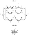
- Fig. 1 illustrates an add/drop device 10 for an N channel WDM optical fiber communication system.
- Each of the paths 12 includes P add/drop filters 13, each filter able to add one channel A ij , and drop one channel D ij .
- the filtered paths are recombined in a M x 1 multiplexer 14 for further transmission in the next segment of transmission fiber, e.g. 9B.
- the add/drop filters 13 separate the drop from the input.
- the demultiplexer 11 is a periodic response demultiplexer such as described in C. Madsen. "A Multiport Band Selector with Inherently Low Loss, Flat Passbands and Low Crosstalk, "IEEE Photon. Technol. Lett., vol. 10, no. 12, pp. 1766-1768. 1998. If we denote successive paths 12 by a subscript j , the periodic response demultiplexer distributes the N channels among the paths 12 i as follows: Path Channels 12 1 1, M+1, 2M+1,...,(P-1)M+1 12 2 2, M+2, 2M+2,...,(P-1)M+2 ... ... 12 m M, 2M, 3M,...(P-1)M+M The demultiplexer has a square passband response and is made using all-pass filters, so that low loss and passband flatness are preserved.
- Fig. 2A illustrates a suitable add/drop filter 13 for this application comprising a Mach-Zehnder interferometer 21 including a pair of arms 22A and 22B with a common Bragg grating 23 formed on both arms.
- the Bragg reflects a dropped channel to the upper input terminal D ij and permits addition of a channel of the same wavelength at output terminal A ij .
- Such add/drop filters are described in detail in T. Amsterdam, T. Strasser, M. Milbrodt, E. Laskowski, C. Henry, and G. Kohnke, "Integrated-Optical Mach-Zehnder Add-Drop Filter Fabricated by a Single UV-Induced Grating Exposure.” Optical Fiber Conference. San Jose.
- the wavelength spacing in each arm 12 is M times the channel spacing, relatively broad filters can be used. Specifically, the desired filtration can be achieved by relatively short Bragg gratings having relatively strong index changes. Due to the large effective channel spacing in each path, out-of-band reflection problems are minimized
- Fig. 2B shows how a plurality of P add/drop filters 13 can be cascaded on a common substrate 24 reducing lossy waveguide crossovers.
- Each of the P filters add/drop for a different signal channel ⁇ 1 , ⁇ 2 ..., ⁇ P .
- the filters 13 are tunable so that their responses can be moved out of the channel passband. This can be effected by thermal or strain tuning the Bragg gratings (21 or 25). The larger effective channel spacing in each arm gives a much larger range for the filter response to be moved without affecting other channels.
- Fig. 3 schematically illustrates an alternative embodiment of an add/drop device 30 wherein the drop can be reflected.
- the P filters 33 in each arm are simply tunable reflective Bragg gratings.
- the reflected dropped channels are taken out from an input circulator 31 and channels can be added by a passive coupler 32 at the output.
- coupler 32 can be replaced by a circulator to reduce the loss in the add operation.
- the P add/drop filters in each of the M paths of Fig. 1 and Fig. 3 may alternatively be composed of a demultiplexer, tunable add/drop filters and multiplexer.
- the device of Fig. 3 with a 1 x P demultiplexer and a P x 1 multiplexer may be used to replace the P individual add/drop filters in one of the paths of Fig. 1.
- tunable grating can be used to tune between two channels (separated by M channel spacings). This reduces the number of gratings needed for dropping.
Landscapes
- Physics & Mathematics (AREA)
- General Physics & Mathematics (AREA)
- Optics & Photonics (AREA)
- Engineering & Computer Science (AREA)
- Computer Networks & Wireless Communication (AREA)
- Signal Processing (AREA)
- Microelectronics & Electronic Packaging (AREA)
- Optical Communication System (AREA)
Abstract
Description
| | Channels | |
| 121 | 1, M+1, 2M+1,...,(P-1)M+1 | |
| 122 | 2, M+2, 2M+2,...,(P-1)M+2 | |
| ... | ... | |
| 12m | M, 2M, 3M,...(P-1)M+M |
Claims (8)
- A reconfigurable add/drop device for a wavelength division multiplexed optical communication system transmitting a signal comprising a plurality N of different wavelength channels, said device comprising:a 1XM demultiplexer, where M is an integer less than N, for dividing the signal among M paths;disposed in each of the M paths, a series of a plurality P of add/drop filters; anda MX1 multiplexer for recombining the M paths.
- The device of claim 1 wherein
- The device of claim 1 wherein the demultiplexer is a periodic response demultiplexer.
- The device of claim 1 wherein a series of add/drop filters includes a tunable add/drop filter.
- The device of claim 1 wherein a series of add/drop filters includes an add/drop filter comprising a Mach-Zehnder interferometer of two arms having a Bragg grating on each arm.
- The device of claim 1 wherein a series of add/drop filters comprises a plurality of Mach-Zehnder add/drop filters with Bragg gratings formed on a common substrate.
- A reconfigurable add/drop device for a wavelength division multiplexed optical communication system transmitting a signal comprising a plurality N of different wavelength channels, said device comprising:a 1XM demultiplexer, where M is an integer less than N, for dividing the signal among M paths;disposed in each of the M paths, at least one tunable grating; anda MX1 multiplexer for recombining the M paths; andan optical coupling device for adding one or more channels to the output of the multiplexer.
- The device of claim 7 wherein said optical coupling device comprises an optical circulator.
Applications Claiming Priority (4)
| Application Number | Priority Date | Filing Date | Title |
|---|---|---|---|
| US12077099P | 1999-02-19 | 1999-02-19 | |
| US120770P | 1999-02-19 | ||
| US09/288,202 US6602000B1 (en) | 1999-02-19 | 1999-04-08 | Reconfigurable add/drop for optical fiber communication systems |
| US288202 | 1999-04-08 |
Publications (3)
| Publication Number | Publication Date |
|---|---|
| EP1033841A2 true EP1033841A2 (en) | 2000-09-06 |
| EP1033841A3 EP1033841A3 (en) | 2005-06-29 |
| EP1033841B1 EP1033841B1 (en) | 2010-01-06 |
Family
ID=26818748
Family Applications (1)
| Application Number | Title | Priority Date | Filing Date |
|---|---|---|---|
| EP00301018A Expired - Lifetime EP1033841B1 (en) | 1999-02-19 | 2000-02-09 | Reconfigurable add/drop for optical fiber communication systems |
Country Status (4)
| Country | Link |
|---|---|
| US (1) | US6602000B1 (en) |
| EP (1) | EP1033841B1 (en) |
| JP (1) | JP3698944B2 (en) |
| DE (1) | DE60043632D1 (en) |
Cited By (4)
| Publication number | Priority date | Publication date | Assignee | Title |
|---|---|---|---|---|
| DE10335419A1 (en) * | 2003-08-02 | 2005-02-17 | Marconi Communications Gmbh | Wavelength-selective optical signal processing device |
| GB2547467A (en) * | 2016-02-19 | 2017-08-23 | Rockley Photonics Ltd | Tunable laser |
| GB2547466A (en) * | 2016-02-19 | 2017-08-23 | Rockley Photonics Ltd | Discrete wavelength tunable laser |
| US11699892B2 (en) | 2016-02-19 | 2023-07-11 | Rockley Photonics Limited | Discrete wavelength tunable laser |
Families Citing this family (17)
| Publication number | Priority date | Publication date | Assignee | Title |
|---|---|---|---|---|
| DE19939853C2 (en) * | 1999-08-23 | 2003-03-13 | Siemens Ag | Add / Drop-Drop & Continue module and Drop & Continue module |
| US7268927B2 (en) * | 2002-03-15 | 2007-09-11 | Corning Incorporated | Tunable optical filter array and method of use |
| US20030175006A1 (en) * | 2002-03-15 | 2003-09-18 | Wildeman George F. | Optical filter array and method of use |
| EP1971060A4 (en) * | 2005-11-29 | 2010-06-02 | G Uchrezhdenie Federalnoe Agen | OPTICAL MULTIPLEXER CONTROL |
| RU2389138C2 (en) * | 2005-11-29 | 2010-05-10 | Федеральное Государственное Учреждение "Федеральное Агентство По Правовой Защите Результатов Интеллектуальной Деятельности Военного, Специального И Двойного Назначения" При Министерстве Юстиции Российской Федерации | Controlled optical multiplexer |
| RU2372728C1 (en) * | 2005-11-29 | 2009-11-10 | Вячеслав Константинович Сахаров | Controlled optical demultiplexer |
| RU2372729C1 (en) * | 2005-11-29 | 2009-11-10 | Вячеслав Константинович Сахаров | Multichannel controlled input/output optical multiplexer |
| WO2007064238A1 (en) * | 2005-11-29 | 2007-06-07 | Nechaev, Alexandr Vladimirovich | Controllable multi-channel optical add/drop multiplexer |
| WO2007064241A1 (en) | 2005-11-29 | 2007-06-07 | Gosudarstvennoe Uchrezhdenie 'federalnoe Agentstvopo Pravovoi Zaschite Rezultatov Intellektualnoi Deyatelnosti Voennogo, Spetsialnogo I Dvoinogo Naznacheniya' Pri Ministerstve Yustitsii Rossiiskoi Fed | Controllable optical add/drop multiplexer |
| RU2390099C2 (en) * | 2005-11-29 | 2010-05-20 | Федеральное Государственное Учреждение "Федеральное Агентство По Правовой Защите Результатов Интеллектуальной Деятельности Военного, Специального И Двойного Назначения" При Министерстве Юстиции Российской Федерации | Controlled optical add/drop multiplexer |
| WO2007064239A1 (en) * | 2005-11-29 | 2007-06-07 | Nechaev, Alexandr Vladimirovich | Controllable optical demultiplexer |
| RU2380837C1 (en) * | 2005-11-29 | 2010-01-27 | Вячеслав Константинович Сахаров | Multichannel optical input/output multiplexer with dynamic functionality |
| WO2007064240A1 (en) * | 2005-11-29 | 2007-06-07 | Nechaev, Alexandr Vladimirovich | Dynamically functional multi-channel controllable optical add/drop multiplexer |
| EP2466768B1 (en) * | 2010-12-17 | 2015-07-29 | Mitsubishi Electric R&D Centre Europe B.V. | Method for coupling an emitting device to a frequency splitter in an optical passive network |
| RU2502194C1 (en) * | 2012-08-01 | 2013-12-20 | Федеральное государственное казенное военное образовательное учреждение высшего профессионального образования "ВОЕННАЯ АКАДЕМИЯ СВЯЗИ имени Маршала Советского Союза С.М. Буденного" Министерства обороны Российской Федерации | Multichannel optical add/drop multiplexer |
| RU2537965C2 (en) * | 2013-04-25 | 2015-01-10 | Федеральное государственное унитарное предприятие "Центральный научно-исследовательский институт связи" (ФГУП ЦНИИС) | Windband passive optical network with wave division |
| RU2537794C2 (en) * | 2013-04-30 | 2015-01-10 | Федеральное государственное унитарное предприятие "Центральный научно-исследовательский институт связи" (ФГУП ЦНИИС) | Optical multiplexer-demultiplexer with division of propagating directions |
Family Cites Families (8)
| Publication number | Priority date | Publication date | Assignee | Title |
|---|---|---|---|---|
| US5136671A (en) * | 1991-08-21 | 1992-08-04 | At&T Bell Laboratories | Optical switch, multiplexer, and demultiplexer |
| US5579143A (en) * | 1993-06-04 | 1996-11-26 | Ciena Corporation | Optical system with tunable in-fiber gratings |
| US5488500A (en) * | 1994-08-31 | 1996-01-30 | At&T Corp. | Tunable add drop optical filtering method and apparatus |
| US5848207A (en) * | 1996-08-29 | 1998-12-08 | Hitachi Cable, Ltd. | Optical device formed with grating therein, add/drop filter using same, and method of fabricating same |
| US5636309A (en) * | 1996-02-21 | 1997-06-03 | Lucent Technologies Inc. | Article comprising a planar optical waveguide mach-zehnder interferometer device, and method of making same |
| US5748349A (en) * | 1996-03-27 | 1998-05-05 | Ciena Corp. | Gratings-based optical add-drop multiplexers for WDM optical communication system |
| JP4031853B2 (en) * | 1997-10-20 | 2008-01-09 | 富士通株式会社 | Optical transmission equipment for bidirectional optical communication |
| US6348984B1 (en) * | 1998-11-05 | 2002-02-19 | Ciena Corporation | Optical add/drop multiplexer |
-
1999
- 1999-04-08 US US09/288,202 patent/US6602000B1/en not_active Expired - Fee Related
-
2000
- 2000-02-09 EP EP00301018A patent/EP1033841B1/en not_active Expired - Lifetime
- 2000-02-09 DE DE60043632T patent/DE60043632D1/en not_active Expired - Lifetime
- 2000-02-18 JP JP2000040396A patent/JP3698944B2/en not_active Expired - Fee Related
Cited By (7)
| Publication number | Priority date | Publication date | Assignee | Title |
|---|---|---|---|---|
| DE10335419A1 (en) * | 2003-08-02 | 2005-02-17 | Marconi Communications Gmbh | Wavelength-selective optical signal processing device |
| GB2547467A (en) * | 2016-02-19 | 2017-08-23 | Rockley Photonics Ltd | Tunable laser |
| GB2547466A (en) * | 2016-02-19 | 2017-08-23 | Rockley Photonics Ltd | Discrete wavelength tunable laser |
| US10594109B2 (en) | 2016-02-19 | 2020-03-17 | Rockley Photonics Limited | Discrete wavelength tunable laser |
| GB2547466B (en) * | 2016-02-19 | 2021-09-01 | Rockley Photonics Ltd | Discrete wavelength tunable laser |
| US11177627B2 (en) | 2016-02-19 | 2021-11-16 | Rockley Photonics Limited | Tunable laser |
| US11699892B2 (en) | 2016-02-19 | 2023-07-11 | Rockley Photonics Limited | Discrete wavelength tunable laser |
Also Published As
| Publication number | Publication date |
|---|---|
| US6602000B1 (en) | 2003-08-05 |
| EP1033841A3 (en) | 2005-06-29 |
| DE60043632D1 (en) | 2010-02-25 |
| JP2000244459A (en) | 2000-09-08 |
| JP3698944B2 (en) | 2005-09-21 |
| EP1033841B1 (en) | 2010-01-06 |
Similar Documents
| Publication | Publication Date | Title |
|---|---|---|
| US6602000B1 (en) | Reconfigurable add/drop for optical fiber communication systems | |
| EP0638837B1 (en) | Device for extraction and re-insertion of an optical carrier in optical communications networks | |
| US5982518A (en) | Optical add-drop multiplexers compatible with very dense WDM optical communication systems | |
| US5774606A (en) | Optical fiber transmission system with a passive optical router | |
| US8781331B2 (en) | Controllable optical add/drop multiplexer | |
| US5748349A (en) | Gratings-based optical add-drop multiplexers for WDM optical communication system | |
| CA2220319C (en) | Hybrid bi-directional wavelength division multiplexing device | |
| US6201907B1 (en) | Optical drop circuit having group delay compensation | |
| US7907844B2 (en) | Method and apparatus for hitless routing of optical signals in an optical transport network | |
| US20030026529A1 (en) | Optical demultiplexer | |
| US6205269B1 (en) | Optical add/drop multiplexer | |
| US7330658B2 (en) | Device and method for optical add/drop multiplexing | |
| US6546167B1 (en) | Tunable grating optical device | |
| US7356219B2 (en) | Integrated optical add/drop device having switching function | |
| WO2001005082A1 (en) | Method and devices for multiplexing and de-multiplexing multiple wavelengths | |
| US7496253B2 (en) | Wide passband optical interleaver | |
| US6768843B1 (en) | Cascaded fourier filter interleaver having enhanced performance | |
| EP1447693A1 (en) | Flexible Passband Filter | |
| Sharma et al. | Optical lattice-type add–drop multiplexing filters and their use in WDM networks | |
| US20050180683A1 (en) | Tuneable filter arrangement | |
| Yuan et al. | Partially reconfigurable optical add-drop multiplexers for dense WDM networks | |
| Madsen et al. | Apodized UV-induced gratings in planar waveguides for compact add-drop filters | |
| AU731587B2 (en) | Optical devices and methods | |
| WO1998036302A1 (en) | Optical devices and methods |
Legal Events
| Date | Code | Title | Description |
|---|---|---|---|
| PUAI | Public reference made under article 153(3) epc to a published international application that has entered the european phase |
Free format text: ORIGINAL CODE: 0009012 |
|
| AK | Designated contracting states |
Kind code of ref document: A2 Designated state(s): AT BE CH CY DE DK ES FI FR GB GR IE IT LI LU MC NL PT SE |
|
| AX | Request for extension of the european patent |
Free format text: AL;LT;LV;MK;RO;SI |
|
| PUAL | Search report despatched |
Free format text: ORIGINAL CODE: 0009013 |
|
| AK | Designated contracting states |
Kind code of ref document: A3 Designated state(s): AT BE CH CY DE DK ES FI FR GB GR IE IT LI LU MC NL PT SE |
|
| AX | Request for extension of the european patent |
Extension state: AL LT LV MK RO SI |
|
| AKX | Designation fees paid |
Designated state(s): DE FR GB |
|
| 17P | Request for examination filed |
Effective date: 20051222 |
|
| 17Q | First examination report despatched |
Effective date: 20060308 |
|
| GRAP | Despatch of communication of intention to grant a patent |
Free format text: ORIGINAL CODE: EPIDOSNIGR1 |
|
| RAP3 | Party data changed (applicant data changed or rights of an application transferred) |
Owner name: LUCENT TECHNOLOGIES INC. |
|
| GRAS | Grant fee paid |
Free format text: ORIGINAL CODE: EPIDOSNIGR3 |
|
| GRAA | (expected) grant |
Free format text: ORIGINAL CODE: 0009210 |
|
| AK | Designated contracting states |
Kind code of ref document: B1 Designated state(s): DE FR GB |
|
| REG | Reference to a national code |
Ref country code: GB Ref legal event code: FG4D |
|
| REF | Corresponds to: |
Ref document number: 60043632 Country of ref document: DE Date of ref document: 20100225 Kind code of ref document: P |
|
| PLBE | No opposition filed within time limit |
Free format text: ORIGINAL CODE: 0009261 |
|
| STAA | Information on the status of an ep patent application or granted ep patent |
Free format text: STATUS: NO OPPOSITION FILED WITHIN TIME LIMIT |
|
| 26N | No opposition filed |
Effective date: 20101007 |
|
| REG | Reference to a national code |
Ref country code: GB Ref legal event code: 732E Free format text: REGISTERED BETWEEN 20131121 AND 20131127 |
|
| REG | Reference to a national code |
Ref country code: FR Ref legal event code: CD Owner name: ALCATEL-LUCENT USA INC. Effective date: 20131122 |
|
| PGFP | Annual fee paid to national office [announced via postgrant information from national office to epo] |
Ref country code: DE Payment date: 20140219 Year of fee payment: 15 |
|
| REG | Reference to a national code |
Ref country code: FR Ref legal event code: GC Effective date: 20140410 |
|
| PGFP | Annual fee paid to national office [announced via postgrant information from national office to epo] |
Ref country code: FR Payment date: 20140219 Year of fee payment: 15 |
|
| PGFP | Annual fee paid to national office [announced via postgrant information from national office to epo] |
Ref country code: GB Payment date: 20140218 Year of fee payment: 15 |
|
| REG | Reference to a national code |
Ref country code: FR Ref legal event code: RG Effective date: 20141015 |
|
| REG | Reference to a national code |
Ref country code: DE Ref legal event code: R119 Ref document number: 60043632 Country of ref document: DE |
|
| GBPC | Gb: european patent ceased through non-payment of renewal fee |
Effective date: 20150209 |
|
| REG | Reference to a national code |
Ref country code: FR Ref legal event code: ST Effective date: 20151030 |
|
| PG25 | Lapsed in a contracting state [announced via postgrant information from national office to epo] |
Ref country code: DE Free format text: LAPSE BECAUSE OF NON-PAYMENT OF DUE FEES Effective date: 20150901 Ref country code: GB Free format text: LAPSE BECAUSE OF NON-PAYMENT OF DUE FEES Effective date: 20150209 |
|
| PG25 | Lapsed in a contracting state [announced via postgrant information from national office to epo] |
Ref country code: FR Free format text: LAPSE BECAUSE OF NON-PAYMENT OF DUE FEES Effective date: 20150302 |