EP1033835A2 - Optical central office - Google Patents
Optical central office Download PDFInfo
- Publication number
- EP1033835A2 EP1033835A2 EP00102400A EP00102400A EP1033835A2 EP 1033835 A2 EP1033835 A2 EP 1033835A2 EP 00102400 A EP00102400 A EP 00102400A EP 00102400 A EP00102400 A EP 00102400A EP 1033835 A2 EP1033835 A2 EP 1033835A2
- Authority
- EP
- European Patent Office
- Prior art keywords
- optical
- carrier signals
- optical carrier
- signals
- wavelength
- Prior art date
- Legal status (The legal status is an assumption and is not a legal conclusion. Google has not performed a legal analysis and makes no representation as to the accuracy of the status listed.)
- Withdrawn
Links
- 230000003287 optical effect Effects 0.000 title claims abstract description 282
- 230000005540 biological transmission Effects 0.000 claims abstract description 28
- 238000000034 method Methods 0.000 claims abstract description 16
- 230000003321 amplification Effects 0.000 claims abstract description 13
- 238000003199 nucleic acid amplification method Methods 0.000 claims abstract description 13
- 239000000969 carrier Substances 0.000 description 69
- 239000013307 optical fiber Substances 0.000 description 31
- 239000000835 fiber Substances 0.000 description 22
- 230000015556 catabolic process Effects 0.000 description 2
- 238000006731 degradation reaction Methods 0.000 description 2
- 238000010586 diagram Methods 0.000 description 2
- 230000009977 dual effect Effects 0.000 description 2
- 229910052691 Erbium Inorganic materials 0.000 description 1
- 230000003292 diminished effect Effects 0.000 description 1
- 230000000694 effects Effects 0.000 description 1
- UYAHIZSMUZPPFV-UHFFFAOYSA-N erbium Chemical compound [Er] UYAHIZSMUZPPFV-UHFFFAOYSA-N 0.000 description 1
- 238000010079 rubber tapping Methods 0.000 description 1
- 239000004065 semiconductor Substances 0.000 description 1
- 238000011144 upstream manufacturing Methods 0.000 description 1
Images


Classifications
-
- H—ELECTRICITY
- H04—ELECTRIC COMMUNICATION TECHNIQUE
- H04B—TRANSMISSION
- H04B10/00—Transmission systems employing electromagnetic waves other than radio-waves, e.g. infrared, visible or ultraviolet light, or employing corpuscular radiation, e.g. quantum communication
- H04B10/27—Arrangements for networking
-
- H—ELECTRICITY
- H04—ELECTRIC COMMUNICATION TECHNIQUE
- H04B—TRANSMISSION
- H04B10/00—Transmission systems employing electromagnetic waves other than radio-waves, e.g. infrared, visible or ultraviolet light, or employing corpuscular radiation, e.g. quantum communication
- H04B10/27—Arrangements for networking
- H04B10/272—Star-type networks or tree-type networks
Definitions
- each individually controllable optical channel must be isolated, so that each optical channel (carrier) can be individually modulated with unique data.
- the preferred embodiment utilizes a master optical source arrangement that utilizes one optical source per carrier wavelength, for a total of 80 optical sources.
- the twice split and once amplified optical carriers are transmitted to 900 separate optical fibers and 900 external modulators.
- the 900 optical carriers at ⁇ 1 can then be individually modulated to carry unique information.
- the distribution of the other optical carrier wavelengths, ⁇ 2 through ⁇ 80 is accomplished in parallel with wavelength ⁇ 1 using the same dual-level splitting used for wavelength ⁇ 1 .
- the optical carriers of the different wavelengths are multiplexed together, using 900 output multiplexers, for transmission via common output distribution optical fibers.
- the multiplexers multiplex one optical carrier from each of the 80 wavelength-specific optical carriers for transmission through each output distribution optical fiber.
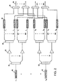
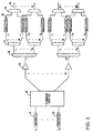
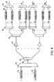
- Figs. 2-4 are expanded depictions of various preferred configurations of the central office 12 that is depicted in Fig. 1.
- the devices incorporated into the various central office configurations include conventional optical communications devices such as wavelength-specific optical energy sources 40 and 42, power splitters 56, 58, 60, 64, 72, and 76, optical amplifiers 52, optical modulators 48, optical multiplexers 44 and 84, and/or optical demultiplexers 68 and 80.
- the optical sources include light emitting diodes, or laser diodes, that emit laser light in the 1,200 to 1,600 nm.
- the preferred laser diodes emit light having wavelength stability and linewidth tolerances compatible with dense wavelength division multiplexing (DWDM).
- DWDM dense wavelength division multiplexing
- the combiner/splitter divides the combined optical carriers into 30 equal multi-wavelength signals.
- the 30 multi-wavelength signals are transmitted through dedicated fibers to respective optical amplifiers 52.
- the optical carriers are transmitted to 30 level-two demultiplexers 68 that demultiplex the combined signals into the 80 different optical carrier wavelengths, ⁇ 1 through ⁇ 80 .
- each wavelength-specific optical carrier is transmitted to a 1 ⁇ 30 level-two splitter 72.
- Fig. 4 is another configuration of a central office that incorporates the master laser diode concept for a system having 80 different wavelength-specific optical carriers that are to be distributed over 900 optical fibers. Similar to the configurations of Figs. 2 and 3, the central office of Fig. 4 includes 80 wavelength-specific master laser diodes 40 and 42 that output wavelength-specific optical carriers at 80 different wavelengths, ⁇ 1 through ⁇ 80 . Although any device that has the net effect of combining and splitting the optical carriers can be used, the combination of an 80 ⁇ 1 multiplexer and a 1 ⁇ 30 is described for example purposes. In Fig.
- an initial level of amplification can alternatively be included in the distribution systems.
- optical amplifiers can be located between each master laser diode 40 and 42 and the respective 1 ⁇ 30 splitters 56 and 58.
- a single optical amplifier can be located between the initial 80 ⁇ 1 multiplexers 84 and the level-one splitters 60.
- All three central office configurations shown in Figs. 2-4 include 80 master laser diodes, 72,000 external modulators, and 900 output multiplexers. However, the type and number of optical devices located between the master laser diodes 40 and 42 and the output multiplexers 44 vary depending on the particular configuration. The variation of optical devices is tabulated in Table 1 for each configuration. Configuration Initial Combiners Level-One Splitters Optical Amplifiers Level-Two Splitters Level-Two Demultiplexers Fig. 2 0 30 2400 2400 0 Fig. 3 1 1 30 2400 30 Fig. 4 1 1 30 30 900
Landscapes
- Engineering & Computer Science (AREA)
- Computing Systems (AREA)
- Physics & Mathematics (AREA)
- Electromagnetism (AREA)
- Computer Networks & Wireless Communication (AREA)
- Signal Processing (AREA)
- Optical Communication System (AREA)
Abstract
Description
| Configuration | Initial Combiners | Level-One Splitters | Optical Amplifiers | Level-Two Splitters | Level-Two Demultiplexers |
| Fig. 2 | 0 | 30 | 2400 | 2400 | 0 |
| Fig. 3 | 1 | 1 | 30 | 2400 | 30 |
| Fig. 4 | 1 | 1 | 30 | 30 | 900 |
Claims (10)
- A method for distributing optical carrier signals in an optical communications system comprising the steps of:generating (130) optical carrier signals from a plurality of optical sources for transmission over a plurality of optical paths, each optical carrier signal having a carrier wavelength;splitting (132) said optical carrier signals a first time for transmission over first segments of said optical paths;amplifying (134) said first split optical carrier signals;splitting (136) said optical carrier signals a second time after said amplification for transmission over second segments of said optical paths, thereby providing multiply split optical carrier signals;modulating (138) data onto at least one of said multiply split optical carrier signals; andmultiplexing (140) at least two of said multiply split optical carrier signals together for transmission over a common optical path.
- The method of claim 1 wherein each said optical source (40 and 42) generates an optical carrier signal at a unique carrier wavelength.
- The method of claim 2 wherein said first step of splitting (132) is performed separately on each said optical carrier signal in order to divide said each optical carrier signal into multiple optical carrier signals of a single carrier wavelength.
- The method of claim 2 or 3 further including a step of combining said optical carrier signals of unique carrier wavelengths from said optical sources (40 and 42) onto a single optical path.
- The method of one of the preceding claims wherein said first step of splitting (132) includes a step of splitting said combined optical carrier signals and wherein said step of amplifying (134) includes a step of amplifying said combined optical carrier signals.
- The method of claim 5 further including a step of demultiplexing said combined optical carrier signals immediately after said step of amplifying (134), and wherein said second step of splitting includes a step of splitting demultiplexed optical carrier signals.
- An optical communications system comprising:a plurality of optical sources (40 and 42) that generate optical carrier signals, with each optical source generating an optical carrier signal having a unique carrier wavelength;a multiplexer (84) connected to receive said optical carrier signals from said optical sources and multiplex said optical carrier signals for transmission over a first optical path;a level-one optical splitter (60) connected to said first optical path to receive said multiplexed optical carrier signals and to split said multiplexed optical carrier signals for transmission over N optical paths, where N is greater than one;N optical amplifiers (52) that are associated with said N optical paths on a one-to-one basis for amplifying said multiplexed optical carrier signals; anda demultiplexer/splitter unit (68 and 72; 76 and 80), connected to receive said optical carrier signals from said optical amplifiers, for demultiplexing said multiplexed optical carrier signals and for splitting said optical carrier signals such that each optical carrier signal of one of said unique carrier wavelengths is transmitted individually over multiple output optical paths.
- The system of claim 7 wherein said demultiplexer/splitter unit (68 and 72) includes N demultiplexers connected one each to said N optical paths, wherein said N demultiplexers separate said optical carrier signals by carrier wavelength for transmission over wavelength-specific optical paths.
- The system of claim 8 wherein said demultiplexer/splitter unit (68 and 72) includes a wavelength-specific level-two splitter associated with each of said wavelength-specific optical paths of said N demultiplexers, and wherein said wavelength-specific level-two splitters divide said demultiplexed optical carrier signals into multiple optical carrier signals for transmission over said multiple output optical paths.
- The system of claim 9 further comprising:a plurality of modulators (48) connected to said multiple output optical paths for individually modulating said optical carrier signals; anda plurality of multiplexers (44) connected to said modulators to multiplex optical carrier signals of unique carrier wavelengths onto common output distribution optical paths.
Applications Claiming Priority (2)
| Application Number | Priority Date | Filing Date | Title |
|---|---|---|---|
| US26141299A | 1999-03-03 | 1999-03-03 | |
| US261412 | 1999-03-03 |
Publications (2)
| Publication Number | Publication Date |
|---|---|
| EP1033835A2 true EP1033835A2 (en) | 2000-09-06 |
| EP1033835A3 EP1033835A3 (en) | 2004-02-11 |
Family
ID=22993193
Family Applications (1)
| Application Number | Title | Priority Date | Filing Date |
|---|---|---|---|
| EP00102400A Withdrawn EP1033835A3 (en) | 1999-03-03 | 2000-02-03 | Optical central office |
Country Status (2)
| Country | Link |
|---|---|
| EP (1) | EP1033835A3 (en) |
| JP (1) | JP2000261414A (en) |
Cited By (3)
| Publication number | Priority date | Publication date | Assignee | Title |
|---|---|---|---|---|
| WO2003103193A3 (en) * | 2002-05-30 | 2005-01-13 | Fujitsu Ltd | Amplifiers for optical networks and method |
| US7075712B2 (en) | 2002-05-30 | 2006-07-11 | Fujitsu Limited | Combining and distributing amplifiers for optical network and method |
| US7085496B2 (en) | 2002-05-30 | 2006-08-01 | Fujitsu Limited | Passive add/drop amplifier for optical networks and method |
Family Cites Families (5)
| Publication number | Priority date | Publication date | Assignee | Title |
|---|---|---|---|---|
| US5221983A (en) * | 1989-01-19 | 1993-06-22 | Bell Communications Research, Inc. | Passive photonic loop architecture employing wavelength multiplexing |
| EP0499065B1 (en) * | 1991-02-11 | 1997-05-28 | Alcatel SEL Aktiengesellschaft | Optical transmission system for the subscriber connection area with optical amplifiers |
| GB9401488D0 (en) * | 1994-01-26 | 1994-03-23 | British Telecomm | Optical communications |
| US5864414A (en) * | 1994-01-26 | 1999-01-26 | British Telecommunications Public Limited Company | WDM network with control wavelength |
| US5557439A (en) * | 1995-07-25 | 1996-09-17 | Ciena Corporation | Expandable wavelength division multiplexed optical communications systems |
-
2000
- 2000-02-03 EP EP00102400A patent/EP1033835A3/en not_active Withdrawn
- 2000-03-01 JP JP2000055713A patent/JP2000261414A/en active Pending
Cited By (3)
| Publication number | Priority date | Publication date | Assignee | Title |
|---|---|---|---|---|
| WO2003103193A3 (en) * | 2002-05-30 | 2005-01-13 | Fujitsu Ltd | Amplifiers for optical networks and method |
| US7075712B2 (en) | 2002-05-30 | 2006-07-11 | Fujitsu Limited | Combining and distributing amplifiers for optical network and method |
| US7085496B2 (en) | 2002-05-30 | 2006-08-01 | Fujitsu Limited | Passive add/drop amplifier for optical networks and method |
Also Published As
| Publication number | Publication date |
|---|---|
| JP2000261414A (en) | 2000-09-22 |
| EP1033835A3 (en) | 2004-02-11 |
Similar Documents
| Publication | Publication Date | Title |
|---|---|---|
| KR100480246B1 (en) | Passive optical network using loop back of multi-wavelength light generated at central office | |
| KR100921797B1 (en) | Passive Optical Subscriber Network System with Wavelength Division Multiplexing | |
| JP4584584B2 (en) | System including wavelength division multiplexed passive optical network and method therefor | |
| JP3504833B2 (en) | Multi-wavelength optical device, transmitter and operation method thereof | |
| US6522803B1 (en) | Optical cross-connect equipment | |
| KR100330409B1 (en) | Wavelength Division Multiplexing Multiplexer / Demultiplexer and Wavelength Division Multiplexing Passive Optical Subscriber Network | |
| US7596319B2 (en) | Wavelength division multiplexing-passive optical network system | |
| US8170418B2 (en) | Protected light source for multiple wavelength division multiplexed passive optical networks (WDM-PONS) | |
| US7209609B2 (en) | Light source apparatus for WDM optical communication and optical communication system | |
| JPH08251109A (en) | Self-amplifying network | |
| US7155124B2 (en) | Loss-less architecture and method for wavelength division multiplexing (WDM) optical networks | |
| KR100990780B1 (en) | Passive Optical Subscriber Network System with Wavelength Division Multiplexing | |
| KR100605925B1 (en) | Passive optical subscriber network of wavelength division multiplex | |
| JP4109296B2 (en) | Central base station and wavelength division multiplexing passive optical network using the same | |
| KR20050117042A (en) | Wavelength division multiplexing passive optical network and optical source generating method | |
| KR20080099056A (en) | Remote Pumping Optical Amplification Wavelength Division Multiplexing Passive Optical Network System | |
| JP2000261414A (en) | Optical carrier signal distribution method | |
| JP3987447B2 (en) | Optical carrier generator, optical modulator, optical signal transmitter / receiver, and optical communication system | |
| US7228075B2 (en) | Wavelength multiplexing apparatus and signal conversion apparatus | |
| KR100533658B1 (en) | Multi-channel light source for passive optical network | |
| CN121864247A (en) | Optical multiplexing section, optical communication system, and optical amplifier |
Legal Events
| Date | Code | Title | Description |
|---|---|---|---|
| PUAI | Public reference made under article 153(3) epc to a published international application that has entered the european phase |
Free format text: ORIGINAL CODE: 0009012 |
|
| AK | Designated contracting states |
Kind code of ref document: A2 Designated state(s): AT BE CH CY DE DK ES FI FR GB GR IE IT LI LU MC NL PT SE |
|
| AX | Request for extension of the european patent |
Free format text: AL;LT;LV;MK;RO;SI |
|
| RAP1 | Party data changed (applicant data changed or rights of an application transferred) |
Owner name: AGILENT TECHNOLOGIES INC. |
|
| RAP1 | Party data changed (applicant data changed or rights of an application transferred) |
Owner name: AGILENT TECHNOLOGIES INC. A DELAWARE CORPORATION |
|
| RAP1 | Party data changed (applicant data changed or rights of an application transferred) |
Owner name: AGILENT TECHNOLOGIES, INC. (A DELAWARE CORPORATION |
|
| PUAL | Search report despatched |
Free format text: ORIGINAL CODE: 0009013 |
|
| AK | Designated contracting states |
Kind code of ref document: A3 Designated state(s): AT BE CH CY DE DK ES FI FR GB GR IE IT LI LU MC NL PT SE |
|
| AX | Request for extension of the european patent |
Extension state: AL LT LV MK RO SI |
|
| RIC1 | Information provided on ipc code assigned before grant |
Ipc: 7H 04J 14/02 B Ipc: 7H 04B 10/207 A |
|
| 17P | Request for examination filed |
Effective date: 20040712 |
|
| 17Q | First examination report despatched |
Effective date: 20040809 |
|
| AKX | Designation fees paid |
Designated state(s): DE FR GB |
|
| STAA | Information on the status of an ep patent application or granted ep patent |
Free format text: STATUS: THE APPLICATION IS DEEMED TO BE WITHDRAWN |
|
| 18D | Application deemed to be withdrawn |
Effective date: 20041221 |