EP1033831A2 - Base station apparatus and frame synchronization acquisition method - Google Patents
Base station apparatus and frame synchronization acquisition method Download PDFInfo
- Publication number
- EP1033831A2 EP1033831A2 EP00104394A EP00104394A EP1033831A2 EP 1033831 A2 EP1033831 A2 EP 1033831A2 EP 00104394 A EP00104394 A EP 00104394A EP 00104394 A EP00104394 A EP 00104394A EP 1033831 A2 EP1033831 A2 EP 1033831A2
- Authority
- EP
- European Patent Office
- Prior art keywords
- base station
- station apparatus
- synchronization
- timing
- frame synchronization
- Prior art date
- Legal status (The legal status is an assumption and is not a legal conclusion. Google has not performed a legal analysis and makes no representation as to the accuracy of the status listed.)
- Withdrawn
Links
Images




Classifications
-
- H—ELECTRICITY
- H04—ELECTRIC COMMUNICATION TECHNIQUE
- H04B—TRANSMISSION
- H04B7/00—Radio transmission systems, i.e. using radiation field
- H04B7/24—Radio transmission systems, i.e. using radiation field for communication between two or more posts
- H04B7/26—Radio transmission systems, i.e. using radiation field for communication between two or more posts at least one of which is mobile
- H04B7/2662—Arrangements for Wireless System Synchronisation
- H04B7/2671—Arrangements for Wireless Time-Division Multiple Access [TDMA] System Synchronisation
- H04B7/2678—Time synchronisation
- H04B7/2687—Inter base stations synchronisation
- H04B7/269—Leader-follower synchronisation
Definitions
- the present invention relates to a base station apparatus and frame synchronization acquisition method in a radio communication system in which frame synchronization is acquired between base station apparatuses.
- FIG.1 is a diagram illustrating a radio communication system including conventional base station apparatuses. It is assumed that base station apparatus 12 synchronizes the frame timing thereof with the frame timing of base station apparatus 11 which is currently a reference of the frame synchronization. It is further assumed that base station apparatus 11 performs communications with mobile station apparatuses 21 and 23 existing in communication area 31 of base station apparatus 11, base station apparatus 12 performs communications with mobile station apparatus 22 existing in communication area 32 of base station apparatus 12, and that base station apparatus 13 starts communicating.
- Base station apparatus 13 acquires the frame timing of base station apparatus 11 which is the reference of the frame synchronization before starting ordinary communications. In this case, since base station apparatus 11 exists out of communication area 33 of base station apparatus 13, base station apparatus 13 cannot receives a signal from base station apparatus 11 directly.
- base station apparatus 13 synchronizes the frame timing thereof with that of base station apparatus 12 to be indirectly in frame synchronization with base station apparatus 11.
- Base station apparatus 13 starts communicating with mobile station apparatus 24 existing in communication area 33 thereof after acquiring the frame synchronization.
- the conventional base station apparatus detects the frame timing of a neighboring base station apparatus to synchronize, the conventional base station apparatus detects the frame timing of the neighboring base station apparatus existing closest thereto, and performs communications in synchronization with the frame timing of such a neighboring base station apparatus.
- FIG.2 is a diagram illustrating the frame timing of each base station apparatus after the frame synchronization acquisition is completed.
- each base station apparatus receives a transmission signal from another base station apparatus to detect the timing
- the transmission timings of frames to mobile station apparatuses from respective base station apparatuses are not completely synchronous, resulting in errors almost equivalent to a guard time.
- Such interference occurs at a portion with oblique lines in FIG.1 where the communication area of base station apparatus 11 and that of base station apparatus 13 overlap each other. Accordingly, as illustrated in FIG.2, the interference occurs when base station apparatus 13 transmits a signal to mobile station apparatus 24 in some frame, and base station apparatus 11 transmits a signal to mobile station apparatus 11 in next frame.
- the apparatus when a base station apparatus with the frame timing as a reference of the frame synchronization does not exist in the communication area of some apparatus, the apparatus does not acquire the frame synchronization directly, but acquires that indirectly, resulting in the problem that errors of frame timings between the base station apparatuses become large, and that the interference occurs.
- An object of the present invention is to provide a base station apparatus and frame synchronization method which do not cause interference between base station apparatuses in the case where a base station apparatus as a reference of frame synchronization does not exist in an ordinary communication area.
- the base station apparatus of the present invention achieves the above object by controlling the directivity of an antenna to receive a transmission signal from the base station apparatus as the reference of frame synchronization directly with the antenna, detecting a transmission timing of the base station apparatus as the reference of synchronization, and controlling the transmission timing thereof in accordance with the detected transmission timing.
- FIG.3 is a diagram illustrating a configuration of a base station apparatus according to the first embodiment of the present invention.
- Switch 104 outputs a signal received at one of antennas 101 to 103 to selector 105, while outputting a transmission signal outputted from selector 105 to one of antennas 101 to 103 to transmit.
- Selector 105 outputs the signal passed through switch 104 to reception section 106, while outputting an output signal from transmission section 112 to switch 104.
- Reception section 106 subjects the received signal passed through selector 105 to processing such as amplification and frequency conversion to output to demodulation section 107.
- Demodulation section 107 executes detection processing on the output signal from reception section 106 to output to UW detection section 108.
- UW detection section 108 fetches a received message from the output signal from demodulation section 107, detects a unique word portion in the received signal, and outputs timing information of neighboring station indicative of the end time of the unique word to timing difference detection section 109.
- Timing detection section 109 detects a difference between the timing of this apparatus and that of the neighboring station outputted from UW detection section 108, and outputs timing difference information that is the detected result to timing control section 110.
- Timing control section 110 controls the transmission timing of transmission section 112 according to the timing difference information detected in timing difference detection section 109.
- Modulation section 111 inserts the unique word to a transmission message, then executes modulation processing, and outputs the resultant signal to transmission section 112.
- Transmission section 112 subjects the output signal from modulation section 111 to processing such as amplification and frequency conversion, and outputs the resultant signal to switch 105 according to a timing based on a control signal outputted from timing control section 110.
- Antenna selection section 113 controls switch 104, while selecting an antenna for use in transmission and reception from antennas 101 to 103, based on directivity control information.
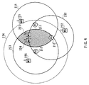
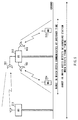
- FIGS.4 and 5 are diagrams illustrating a radio communication system including a base station apparatus according to this embodiment.
- FIG.4 is a top view
- FIG.5 is an elevation view.
- synchronization master station 211 communicates with mobile station apparatuses 221 and 223 existing in communication area 231 of the master station 211
- base station apparatus 212 communicates with mobile station apparatus 222 existing in communication area 232 of the apparatus 212
- base station apparatus 213 illustrated in FIG.3 starts communicating.
- Base station apparatus 213 acquires frame synchronization before starting communicating. In this case, by selecting an antenna for the frame synchronization, the apparatus 213 expands the communication area in the horizontal direction. In FIG.4, communication area 234 is for use by base station apparatus 213 to acquire the frame synchronization.
- antenna 101 for use in acquiring the frame synchronization points to the direction of base station apparatus 211, and provides the communication area which is broader in the horizontal direction than those of other antennas pointing to mobile stations.
- Base station apparatus 213 connects antenna 101 to switch 105 according to the control from antenna selection section 113, expands the communication area in the horizontal direction, and thus enables direct reception of the transmission signal from synchronization master station 211.
- base station apparatus 213 communicates with mobile station apparatuses 224 and 225 existing in the communication area using antennas 102 and 103.
- antenna 101 for use in acquiring the frame synchronization is not used in transmission.
- FIG.6A, FIG.6B and FIG.6C illustrate frame timing diagrams in the case where the frame synchronization is corrected.
- FIG.6A illustrates a frame timing diagram of a transmission signal of the synchronization master station
- FIG.6B illustrates a frame timing diagram of a transmission signal of base station apparatus 213 in the case where the apparatus transmits a signal based on only the timing information of the apparatus.
- Timing difference detection section 109 detects the transmission timing difference X between the apparatus and the synchronization master station, and timing control section 110 controls the transmission timing in transmission section 112 to set that forward by X[sec].
- FIG.6C illustrates a frame timing diagram of the transmission signal of base station apparatus 213 after the transmission timing is controlled.
- the communication area for use in acquiring the frame synchronization is expanded by switching an antenna with the switch in this embodiment, it may be possible to expand the communication area by changing the antenna directivity upward in the direction vertical to the ground, or increasing the height of an antenna. These operations make the switch for use in switching an antenna no need.
- Second embodiment explains the case where a base station apparatus directly receives a signal transmitted from the synchronization master station using an adaptive array reception method to detect the frame timing.
- FIG.7 is a block diagram for explaining a schematic configuration of the base station apparatus according to the second embodiment of the present invention.
- components common to those in the base station apparatus illustrated in FIG.3 are given the same marks as in FIG.3 to omit explanations thereof.
- Selector 304 outputs a signal received at antenna 301 to reception section 307, while outputting an output signal from transmission section 112 to antenna 301.
- Selector 305 outputs a signal received at antenna 302 to reception section 308, while outputting an output signal from transmission section 112 to antenna 302.
- Selector 306 outputs a signal received at antenna 303 to reception section 309, while outputting an output signal from transmission section 112 to antenna 303.
- Reception section 307 subjects the received signal passed through selector 304 to processing such as amplification and frequency conversion.
- Reception section 308 subjects the received signal passed through selector 305 to processing such as amplification and frequency conversion.
- Reception section 309 subjects the received signal passed through selector 306 to processing such as amplification and frequency conversion.
- Combining section 310 combines the received signals outputted from reception sections 307 to 309 according to the combining method instructed by combining method control section 311, and outputs the resultant signal to demodulation section 107.
- Combining method control section 311 controls the combining method in combining section 310 based on combining method control information.
- FIG.8 is a diagram illustrating a radio communication system including the base station apparatus according to this embodiment.
- base station apparatus 412 illustrated in FIG.7 synchronizes the frame timing with that of the synchronization master station 411.
- Base station apparatus 412 expands the communication area with the adaptive array reception method before starting communicating.
- base station apparatus 412 obtains communication area 421 by using an omnidirectional antenna, and further obtains communication area 422 by using the adaptive array reception method when acquires the frame synchronization.
- base station apparatus 412 when the omnidiretional antenna is used, since synchronization master station 411 exists out of communication area 421 of the apparatus 412, base station apparatus 412 cannot receive a signal from base station apparatus 411. On the contrary, when the adaptive array reception method is used, since base station apparatus 412 can form the communication area in such a manner that base station apparatus 411 exists within the communication area 422 of the apparatus 412 by pointing the antenna directivity to the direction of base station apparatus 411, the apparatus 412 can directly receive the transmission signal from base station apparatus 411.
- base station apparatus 412 cancels the interference signal from interference station 413, and consequently can receive the transmission signal from base station apparatus 411 stably.
- executing reception with the adaptive array reception method enables the apparatus to receive a transmission signal from a desired station existing far from the apparatus, further to cancel the interference signal from the interference station, and therefore to assuredly synchronize the frame timing thereof with that of the base station apparatus as the reference of the frame synchronization.
- the adaptive array processing is used as combining method to cancel interference in the case where the frame timing of the synchronization master station is detected in this embodiment, it may be effective to use other methods such as adaptive diversity reception method to cancel the interference.
- FIG.9 is a block diagram for explaining a schematic configuration of a base station apparatus according to the third embodiment of the present invention.
- components common to those in the base station apparatus illustrated in FIG.7 are given the same marks as in FIG.7 to omit explanations thereof.
- UW detection section 108 fetches a received message from an output signal from demodulation section 107, detects a unique word portion in a received signal, and outputs the timing information of neighboring station indicative of the end time of the unique word to timing difference detection section 109 and asynchronous detection section 501.
- Timing control section 110 controls the transmission section according to timing difference information detected by timing difference detection section 109, and controls a transmission timing of a transmission signal, while outputting the timing information of this apparatus to asynchronous detection section 501.
- Asynchronous detection section 501 monitors in ordinary communications whether the frame timing of the apparatus and that of the synchronization master station are synchronous based on the timing information of the apparatus inputted from timing control section 110 and the timing information of the synchronization master station inputted from UW detection section 108.
- asynchronous detection section 501 changes the combining method of combining method control section 311 to the adaptive array reception method to expand the communication area, and using the expanded communication area, executes the frame synchronization processing.
- the base station apparatus monitors in ordinary communications whether or not the frame timing of the apparatus and that of the synchronization master station are synchronous, and when the frame timing of the apparatus and that of the synchronization master station are not synchronous, receives the signal transmitted from the synchronization master station by expanding the communication area, and synchronizes the frame timing thereof with that of the synchronization master station.
- the apparatus can acquire the frame synchronization again.
- a new base station apparatus of which the frame timing is not synchronized with that of the apparatus according to this embodiment, is installed around the apparatus after the apparatus is installed, the apparatus can acquire the frame synchronization from the new base station apparatus.
- the base station apparatus and frame synchronization acquisition method of the present invention since it is possible to directly receive a transmission signal from the base station apparatus as the reference of the frame synchronization by expanding the antenna directivity of the apparatus, the frame timing can be detected assuredly.
Landscapes
- Engineering & Computer Science (AREA)
- Computer Networks & Wireless Communication (AREA)
- Signal Processing (AREA)
- Mobile Radio Communication Systems (AREA)
- Synchronisation In Digital Transmission Systems (AREA)
- Radio Transmission System (AREA)
Abstract
Description
Claims (7)
- A base station apparatus comprising:directivity control means (104,105,112,113,304∼ 306) for controlling a directivity of an antenna to receive a transmission signal from another base station apparatus as a reference of synchronization directly with said antenna;timing detection means (109) for detecting a transmission timing of the base station apparatus as the reference of synchronization; andtransmission timing control means (110) for controlling the transmission timing of said apparatus in accordance with the transmission timing detected in the timing detection means.
- The base station apparatus according to claim 1, wherein said directivity control means (112,304∼306) controls the directivity of an adaptive array antenna in order not to receive a transmission signal from an interference station.
- The base station apparatus according to claim 1, further comprising:asynchronous detection means (501) for detecting a difference of the transmission timing between the apparatus and the base station apparatus as the reference of synchronization,
wherein the transmission timing control means corrects the transmission timing in the case where the asynchronous detection section detects the difference. - A communication terminal apparatus which performs a radio communication with the base station apparatus according to claim 1.
- A frame synchronization acquisition method comprising:controlling a directivity of an antenna to receive a transmission signal from another base station apparatus as a reference of synchronization directly with said antenna;detecting a transmission timing of the base station apparatus as the reference of synchronization; andcontrolling the transmission timing of a base station apparatus in accordance with a detected transmission timing.
- The frame synchronization acquisition method according to claim 5, further comprising:controlling the directivity of an adaptive array antenna in order not to receive a transmission signal from an interference station.
- The frame synchronization acquisition method according to claim 5, further comprising:detecting a difference of the transmission timing between the base station apparatus and the base station apparatus as the reference of synchronization; andcorrecting the transmission timing in the case where the difference is detected.
Applications Claiming Priority (2)
| Application Number | Priority Date | Filing Date | Title |
|---|---|---|---|
| JP11056811A JP2000253446A (en) | 1999-03-04 | 1999-03-04 | Base station apparatus and frame synchronization acquisition method |
| JP5681199 | 1999-03-04 |
Publications (2)
| Publication Number | Publication Date |
|---|---|
| EP1033831A2 true EP1033831A2 (en) | 2000-09-06 |
| EP1033831A3 EP1033831A3 (en) | 2003-07-09 |
Family
ID=13037772
Family Applications (1)
| Application Number | Title | Priority Date | Filing Date |
|---|---|---|---|
| EP00104394A Withdrawn EP1033831A3 (en) | 1999-03-04 | 2000-03-02 | Base station apparatus and frame synchronization acquisition method |
Country Status (4)
| Country | Link |
|---|---|
| US (1) | US6298248B1 (en) |
| EP (1) | EP1033831A3 (en) |
| JP (1) | JP2000253446A (en) |
| CN (1) | CN1156187C (en) |
Cited By (2)
| Publication number | Priority date | Publication date | Assignee | Title |
|---|---|---|---|---|
| KR20020030867A (en) * | 2000-10-18 | 2002-04-26 | 구자홍 | Data transmitting method based on antenna diversity for mobile communication system |
| DE10213262A1 (en) * | 2002-03-25 | 2003-10-23 | Infineon Technologies Ag | Device and method for controlling a transmission time of a continuous-time transmission signal |
Families Citing this family (18)
| Publication number | Priority date | Publication date | Assignee | Title |
|---|---|---|---|---|
| US8290351B2 (en) | 2001-04-03 | 2012-10-16 | Prime Research Alliance E., Inc. | Alternative advertising in prerecorded media |
| US20020178447A1 (en) * | 2001-04-03 | 2002-11-28 | Plotnick Michael A. | Behavioral targeted advertising |
| US20020184047A1 (en) * | 2001-04-03 | 2002-12-05 | Plotnick Michael A. | Universal ad queue |
| US7415291B1 (en) * | 2001-09-28 | 2008-08-19 | At&T Delaware Intellectual Property, Inc. | Device and method for augmenting cellular telephone audio signals |
| US20030149975A1 (en) * | 2002-02-05 | 2003-08-07 | Charles Eldering | Targeted advertising in on demand programming |
| EP1392069B1 (en) * | 2002-02-18 | 2015-04-01 | Sony Corporation | Wireless communication system, wireless communication device and wireless communication method, and computer program |
| JP2003332940A (en) * | 2002-05-09 | 2003-11-21 | Matsushita Electric Ind Co Ltd | Mobile communication device |
| US7065373B2 (en) * | 2002-10-18 | 2006-06-20 | Itt Manufacturing Enterprises, Inc. | Method of steering smart antennas |
| EP1416648A1 (en) * | 2002-10-28 | 2004-05-06 | Siemens Aktiengesellschaft | Method for decentralized synchronization in a self-organizing radio communication system |
| EP1612965A3 (en) * | 2004-07-01 | 2012-01-04 | NEC Corporation | Antenna selector |
| CA2575031A1 (en) * | 2004-07-30 | 2006-02-02 | Matsushita Electric Industrial Co., Ltd. | Base station device and wireless communication method |
| US7301608B1 (en) | 2005-01-11 | 2007-11-27 | Itt Manufacturing Enterprises, Inc. | Photon-counting, non-imaging, direct-detect LADAR |
| JP2007295031A (en) * | 2006-04-20 | 2007-11-08 | Toyota Motor Corp | Wireless communication system |
| CN101047430B (en) * | 2006-06-16 | 2010-09-08 | 华为技术有限公司 | A method and system for selecting a base station |
| CN102396276B (en) * | 2009-02-02 | 2015-08-05 | 三菱电机株式会社 | mobile communication system |
| US10372860B2 (en) | 2015-07-01 | 2019-08-06 | Synopsys, Inc. | Netlist abstraction for circuit design floorplanning |
| US9697322B2 (en) | 2015-07-09 | 2017-07-04 | International Business Machines Corporation | Hierarchical wire-pin co-optimization |
| US9858377B2 (en) | 2015-11-10 | 2018-01-02 | International Business Machines Corporation | Constraint-driven pin optimization for hierarchical design convergence |
Family Cites Families (12)
| Publication number | Priority date | Publication date | Assignee | Title |
|---|---|---|---|---|
| US4231114A (en) * | 1978-02-27 | 1980-10-28 | Motorola, Inc. | Synchronizing means for a two-way communication system |
| JPS58151142A (en) * | 1982-03-04 | 1983-09-08 | Nec Corp | Time division multiplex connecting device |
| JPH05308333A (en) | 1992-04-28 | 1993-11-19 | Kokusai Electric Co Ltd | Frame synchronization system of tdma system radio base station |
| US5613211A (en) * | 1992-10-07 | 1997-03-18 | Nippon Steel Corporation | Method of establishing inter base-station synchronization and mobile radio communicaton system using the method |
| JP2606590B2 (en) * | 1994-06-30 | 1997-05-07 | 日本電気株式会社 | Inter-station synchronization method |
| JP2600622B2 (en) * | 1994-09-22 | 1997-04-16 | 日本電気株式会社 | Transmission control method of downlink control signal in TDMA mobile communication system |
| JP3432335B2 (en) * | 1995-06-27 | 2003-08-04 | 株式会社東芝 | Mobile radio communication device |
| BR9612025A (en) * | 1995-12-15 | 1999-06-29 | Ericsson Telefon Ab L M | Digital phase retaining ring circuit and base station |
| JP2915851B2 (en) * | 1996-07-18 | 1999-07-05 | 宇宙開発事業団 | Time synchronous communication system |
| US6112088A (en) * | 1996-08-30 | 2000-08-29 | Telefonaktiebolaget, L.M. Ericsson | Radio communications system and method for mobile assisted handover between a private network and a public mobile network |
| JP2845228B2 (en) * | 1996-12-10 | 1999-01-13 | 日本電気株式会社 | Neighbor cell synchronization detection method |
| US6119016A (en) * | 1998-06-10 | 2000-09-12 | Lucent Technologies, Inc. | Synchronizing base stations in a wireless telecommunications system |
-
1999
- 1999-03-04 JP JP11056811A patent/JP2000253446A/en active Pending
-
2000
- 2000-02-28 US US09/514,194 patent/US6298248B1/en not_active Expired - Fee Related
- 2000-03-02 EP EP00104394A patent/EP1033831A3/en not_active Withdrawn
- 2000-03-03 CN CNB001038141A patent/CN1156187C/en not_active Expired - Fee Related
Cited By (4)
| Publication number | Priority date | Publication date | Assignee | Title |
|---|---|---|---|---|
| KR20020030867A (en) * | 2000-10-18 | 2002-04-26 | 구자홍 | Data transmitting method based on antenna diversity for mobile communication system |
| DE10213262A1 (en) * | 2002-03-25 | 2003-10-23 | Infineon Technologies Ag | Device and method for controlling a transmission time of a continuous-time transmission signal |
| DE10213262B4 (en) * | 2002-03-25 | 2005-11-10 | Infineon Technologies Ag | Device and method for controlling a transmission time of a continuous-time transmission signal |
| US7263338B2 (en) | 2002-03-25 | 2007-08-28 | Infineon Technologies Ag | Device and method for regulating a transmission moment of a continuous transmission signal |
Also Published As
| Publication number | Publication date |
|---|---|
| US6298248B1 (en) | 2001-10-02 |
| CN1156187C (en) | 2004-06-30 |
| EP1033831A3 (en) | 2003-07-09 |
| JP2000253446A (en) | 2000-09-14 |
| CN1266342A (en) | 2000-09-13 |
Similar Documents
| Publication | Publication Date | Title |
|---|---|---|
| US6298248B1 (en) | Base station apparatus and frame synchronization acquisition method | |
| JP4912974B2 (en) | Timing advance and timing deviation synchronization | |
| JP2974980B2 (en) | Method and apparatus for synchronizing communications in a satellite-based telecommunications system | |
| US7894411B2 (en) | Base station apparatus and termnal apparatus | |
| AU722703B2 (en) | Radio communication apparatus and radio communication method | |
| JPH07284141A (en) | Hand-over method | |
| US7466989B2 (en) | Synchronization method for terminal-to-terminal direct communication in time division duplex mobile communication system | |
| US7020437B2 (en) | Radio communication system and frame synchronizing method between base stations | |
| JP2000013867A (en) | Mobile station transmission timing correction method | |
| EP1170881B1 (en) | Mobile communication system and method and mobile stations and base stations in the system | |
| JPH1051376A (en) | Communication synchronization method between mobile stations and communication synchronization system between mobile stations | |
| JP2000050351A (en) | Mobile communication device and method for establishing synchronization in mobile communication | |
| JP2009171228A (en) | Reference signal generator, base station system, and signal transmission method | |
| JPH08116569A (en) | Radio transmission system,central radio station and radio station | |
| JP2000078065A (en) | Wireless line relay device and wireless line relay method | |
| KR20040028585A (en) | Satellite communication system, receiving earth station and communication satellite hand-over method | |
| JP2000354020A (en) | Receiver | |
| KR100777515B1 (en) | Handoff Method in Asynchronous Mobile Communication System | |
| JP2002124898A (en) | Satellite communication ground station | |
| HK1088447B (en) | Synchronization of timing advance and deviation | |
| JPS5930332A (en) | Radio transmission system |
Legal Events
| Date | Code | Title | Description |
|---|---|---|---|
| PUAI | Public reference made under article 153(3) epc to a published international application that has entered the european phase |
Free format text: ORIGINAL CODE: 0009012 |
|
| AK | Designated contracting states |
Kind code of ref document: A2 Designated state(s): AT BE CH CY DE DK ES FI FR GB GR IE IT LI LU MC NL PT SE |
|
| AX | Request for extension of the european patent |
Free format text: AL;LT;LV;MK;RO;SI |
|
| PUAL | Search report despatched |
Free format text: ORIGINAL CODE: 0009013 |
|
| AK | Designated contracting states |
Designated state(s): AT BE CH CY DE DK ES FI FR GB GR IE IT LI LU MC NL PT SE |
|
| AX | Request for extension of the european patent |
Extension state: AL LT LV MK RO SI |
|
| RIC1 | Information provided on ipc code assigned before grant |
Ipc: 7H 04J 3/06 B Ipc: 7H 04B 7/26 A |
|
| 17P | Request for examination filed |
Effective date: 20031016 |
|
| 17Q | First examination report despatched |
Effective date: 20031119 |
|
| AKX | Designation fees paid |
Designated state(s): DE |
|
| GRAP | Despatch of communication of intention to grant a patent |
Free format text: ORIGINAL CODE: EPIDOSNIGR1 |
|
| STAA | Information on the status of an ep patent application or granted ep patent |
Free format text: STATUS: THE APPLICATION IS DEEMED TO BE WITHDRAWN |
|
| 18D | Application deemed to be withdrawn |
Effective date: 20051018 |