EP1033783A2 - Antenna array having reduced sensitivity to frequency-shift effects - Google Patents
Antenna array having reduced sensitivity to frequency-shift effects Download PDFInfo
- Publication number
- EP1033783A2 EP1033783A2 EP00301367A EP00301367A EP1033783A2 EP 1033783 A2 EP1033783 A2 EP 1033783A2 EP 00301367 A EP00301367 A EP 00301367A EP 00301367 A EP00301367 A EP 00301367A EP 1033783 A2 EP1033783 A2 EP 1033783A2
- Authority
- EP
- European Patent Office
- Prior art keywords
- array
- sub
- elements
- wavelength
- signals
- Prior art date
- Legal status (The legal status is an assumption and is not a legal conclusion. Google has not performed a legal analysis and makes no representation as to the accuracy of the status listed.)
- Granted
Links
Images


Classifications
-
- H—ELECTRICITY
- H01—ELECTRIC ELEMENTS
- H01Q—ANTENNAS, i.e. RADIO AERIALS
- H01Q21/00—Antenna arrays or systems
- H01Q21/06—Arrays of individually energised antenna units similarly polarised and spaced apart
- H01Q21/08—Arrays of individually energised antenna units similarly polarised and spaced apart the units being spaced along or adjacent to a rectilinear path
-
- A—HUMAN NECESSITIES
- A61—MEDICAL OR VETERINARY SCIENCE; HYGIENE
- A61G—TRANSPORT, PERSONAL CONVEYANCES OR ACCOMMODATION SPECIALLY ADAPTED FOR PATIENTS OR DISABLED PERSONS; OPERATING TABLES OR CHAIRS; CHAIRS FOR DENTISTRY; FUNERAL DEVICES
- A61G17/00—Coffins; Funeral wrappings; Funeral urns
- A61G17/007—Coffins; Funeral wrappings; Funeral urns characterised by the construction material used, e.g. biodegradable material; Use of several materials
-
- A—HUMAN NECESSITIES
- A61—MEDICAL OR VETERINARY SCIENCE; HYGIENE
- A61G—TRANSPORT, PERSONAL CONVEYANCES OR ACCOMMODATION SPECIALLY ADAPTED FOR PATIENTS OR DISABLED PERSONS; OPERATING TABLES OR CHAIRS; CHAIRS FOR DENTISTRY; FUNERAL DEVICES
- A61G17/00—Coffins; Funeral wrappings; Funeral urns
- A61G17/004—Coffins; Funeral wrappings; Funeral urns specially adapted to be cremated
-
- H—ELECTRICITY
- H01—ELECTRIC ELEMENTS
- H01Q—ANTENNAS, i.e. RADIO AERIALS
- H01Q1/00—Details of, or arrangements associated with, antennas
- H01Q1/12—Supports; Mounting means
- H01Q1/22—Supports; Mounting means by structural association with other equipment or articles
- H01Q1/24—Supports; Mounting means by structural association with other equipment or articles with receiving set
- H01Q1/241—Supports; Mounting means by structural association with other equipment or articles with receiving set used in mobile communications, e.g. GSM
- H01Q1/246—Supports; Mounting means by structural association with other equipment or articles with receiving set used in mobile communications, e.g. GSM specially adapted for base stations
-
- H—ELECTRICITY
- H01—ELECTRIC ELEMENTS
- H01Q—ANTENNAS, i.e. RADIO AERIALS
- H01Q21/00—Antenna arrays or systems
- H01Q21/06—Arrays of individually energised antenna units similarly polarised and spaced apart
- H01Q21/061—Two dimensional planar arrays
-
- H—ELECTRICITY
- H01—ELECTRIC ELEMENTS
- H01Q—ANTENNAS, i.e. RADIO AERIALS
- H01Q21/00—Antenna arrays or systems
- H01Q21/06—Arrays of individually energised antenna units similarly polarised and spaced apart
- H01Q21/22—Antenna units of the array energised non-uniformly in amplitude or phase, e.g. tapered array or binomial array
-
- Y—GENERAL TAGGING OF NEW TECHNOLOGICAL DEVELOPMENTS; GENERAL TAGGING OF CROSS-SECTIONAL TECHNOLOGIES SPANNING OVER SEVERAL SECTIONS OF THE IPC; TECHNICAL SUBJECTS COVERED BY FORMER USPC CROSS-REFERENCE ART COLLECTIONS [XRACs] AND DIGESTS
- Y02—TECHNOLOGIES OR APPLICATIONS FOR MITIGATION OR ADAPTATION AGAINST CLIMATE CHANGE
- Y02W—CLIMATE CHANGE MITIGATION TECHNOLOGIES RELATED TO WASTEWATER TREATMENT OR WASTE MANAGEMENT
- Y02W30/00—Technologies for solid waste management
- Y02W30/50—Reuse, recycling or recovery technologies
- Y02W30/64—Paper recycling
Definitions
- This invention relates to antenna arrays, and more particularly, to antenna arrays used for uplink and downlink communication in cellular and other wireless communication systems.
- Every antenna has a directionally-dependent response function, which is often referred to as the "radiation pattern” in transmission, and as the "sensitivity pattern” in reception. It has long been known that when multiple antenna elements are assembled in an antenna array, the shape of this response function can be tailored by applying suitable complex-valued weights (which combine specified phase delays with specified attenuation coefficients) to the respective elements.
- suitable complex-valued weights which combine specified phase delays with specified attenuation coefficients
- One particular known advantage of such arrays is that by actively changing the weight coefficients, it is possible to maximize the transmitted or received power in a specified direction.
- An antenna array effective for that purpose is one example of an adaptive array.
- each base station In the field of cellular communications, it is an ideal, but generally unreachable, goal for each base station to transmit power only to mobile stations within a designated reception area, and to be sensitive to transmissions only from those mobile stations.
- One proposed approach to this goal is for the base station to transmit and receive using an adaptive array that seeks to maximize its response function at the mobile stations within its reception area.
- each element of the array can measure a respective propagation coefficient characterizing the physical channel between itself and that mobile station.
- This coefficient is desirably sampled over time.
- the propagation coefficient from each mobile station in turn, can be sampled in each of the, e.g., 162 symbol periods that occupy that mobile station's time slot.
- the time-averaged samples can be assembled into a covariance matrix for each mobile station.
- a technique has been described for obtaining, from each of these covariance matrices, a set of weight coefficients that will tend to concentrate the response function in the direction of the pertinent mobile station. This technique is described, e.g., in G.G. Raleigh et al., "Adaptive Antenna Transmission for Frequency Duplex Digital Wireless Communication," Proc. Int. Conf. Comm. , Montreal, Canada (June 1997).
- FDD frequency-division duplex transmission
- the response function of an antenna array is dependent upon the frequency of transmission or reception. Therefore, in a FDD system, the uplink sensitivity pattern is different from the downlink radiation pattern.
- a set of weight coefficients derived adaptively on the uplink to provide a certain directionality will not, in general, provide the same directionality on the downlink.
- the base station Because of the obstacles described above, it is desirable to provide the base station with a system of antennas that can obtain statistical information concerning the uplink propagation coefficients, and then obtain weights from this statistical information for use on the downlink.
- One disadvantage is the expense of a second antenna installation.
- Another disadvantage relates to the relative siting of the respective antenna arrays. If the arrays are sited too close to each other, they will suffer undesirable mutual coupling effects. If, on the other hand, they are sited too far from each other, the weights selected from the uplink measurements may not function properly on the downlink, at least for relatively close mobile stations.
- our invention involves a system for sending wireless communication signals on at least one downlink wavelength and receiving wireless communication signals on at least one uplink wavelength, wherein there is a ratio r equal to the larger divided by the smaller of these wavelengths.
- the system comprises a receiver operative to receive signals imposed on a carrier having the uplink wavelength, a transmitter operative to transmit signals imposed on a carrier having the downlink wavelength, and an array of independent antenna elements. (By "independent” is meant that these elements can be separately driven, or separately used for the reception of radiofrequency signals.)
- the array comprises a first and a second sub-array.
- One sub-array is electrically coupled to the transmitter, such that transmitted signals can be radiated from it, and the other sub-array is electrically coupled to the receiver, such that signals to be received can be extracted from it.
- each antenna element of one array has a counterpart in the other sub-array, and corresponding inter-element spacings stand in a constant ratio.
- the constant ratio is a scale factor that relates the dimensions of one sub-array to the dimensions of the other. This scale factor is equal to the wavelength ratio r .
- the sub-arrays have at least one common antenna element.
- the elements of the full array are arranged in a one-, two- or three-dimensional array having, respectively, one, two, or three lattice directions. At least three elements, and not more than a respective maximum number of elements, are arranged from first to last along each lattice direction of the array. Along each lattice direction, the elements are spaced with a constant ratio between successive spacings.
- the array comprises first and second sub-arrays. Along each lattice direction, there is at least one row in which the first M-1 elements belong to the first sub-array, and the last M-1 elements belong to the second sub-array, where M is the respective maximum number of elements along that lattice direction.
- an illustrative linear antenna array has M antenna elements 10.1, 10.2,. . ., 10.M.
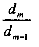
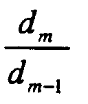
- the elements are here numbered such that d m increases for increasing m .
- One of two wavelengths ⁇ 1 , ⁇ 2 is used for receiving signals (e.g., for the uplink in a wireless communication system), and the other is used for transmitting signals (e.g., for the downlink in a wireless communication system).
- the ratio (using the illustrative convention for numbering the antenna elements) is equal to the ratio of the longer of these wavelengths to the shorter.
- elements 1 through M-1 are used for the function that takes place on the shorter wavelength.
- elements 2 through M are used for the function that takes place on the longer wavelength.
- an antenna array for a wireless communication system may use an uplink wavelength ⁇ 1 which is 10% longer than downlink wavelength ⁇ 2 .
- each inter-element spacing after the first will be 1.1 times the preceding spacing.
- the first M-1 elements will comprise the downlink sub-array (shown in FIG. 1 as sub-array 15), and the last M-1 elements will comprises the uplink sub-array (shown in the figure as sub-array 20).
- the overall size of the full (i.e., uplink plus downlink) antenna array will be determined by the number of elements and the first inter-element spacing d .
- the spacing d should not be so small that there is undesirable coupling between antenna elements. On the other hand, if this spacing is made too large, desired directionalities in the response function of the antenna array will be degraded.
- a currently preferred spacing d is about one-half the shorter of the two operating wavelengths. Departures from such half-wavelength spacing may be permissible in accordance with known techniques of antenna design. In practice, at least a modest range of wavelengths will generally be available for transmission and reception, provided only that each pair of uplink and downlink wavelengths should stand in substantially the same ratio.
- our antenna array will generally work best in communication with terminals (exemplarily, mobile stations) situated in the far field, although it is not limited to far-field operation.
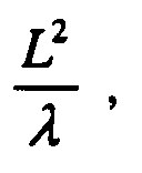
- a terminal is considered to lie in the far field if its distance from the antenna array is greater than where L is the length of the array, and ⁇ is the operating (uplink or downlink) wavelength.
- the uplink and downlink sub-arrays will have the same response function only if each of the antenna elements, individually, has an omnidirectional response function. Otherwise, the response function of the array will be (spatially) modulated by the element response function, which may be different for the two operating wavelengths.
- FIG. 2 shows an illustrative two-dimensional array of 34 elements.
- the elements 25 of this array are assumed to be numbered from left to right, and from top to bottom.
- the array shown in the figure has mutually perpendicular lattice directions lying along respective horizontal and vertical axes.
- the same initial inter-element spacing d is used in both lattice directions.
- the maximum number M of elements along each lattice direction of the array shown in the figure is six.
- the lattice directions may form an angle other than 90°; for example, the antenna elements may form a hexagonal lattice, in which there is an angle of 60° between the lattice directions.
- the initial spacing d may differ in different lattice directions.
- the maximum number of elements along one lattice direction need not equal the maximum number of elements along a different lattice direction.
- the same ratio r between successive inter-element spacings should be applied in all lattice directions.
- a sub-array 30 for operating at the shorter wavelength is obtained by taking the first M-1 (i.e., the first 5, in the example shown) elements along each lattice direction.
- the result is to exclude from sub-array 30 the last row 35 of elements and the last column 40 of elements.
- a sub-my 45 for operating at the longer wavelength is obtained by taking the last M-1 elements along each lattice direction.
- the result is to exclude from sub-array 45 the first row 50 of elements, and the first column 55 of elements.
- neither sub-array would include an element situated at the intersection of the first row and last column, or at the intersection of the last row and first column. Such an element would be redundant, and could be omitted entirely from the full array, as shown in the figure.
- FIG. 3 depicts an illustrative three-dimensional array.
- the number of elements in the depicted array is limited to 15.
- the principles of array design illustrated here are, however, readily applied to the design of arrays having greater numbers of elements.
- the array of FIG. 3 has a rectangular parallelepipedal lattice structure with the same initial spacing d in all three lattice directions.
- the first antenna element of the array is element 70.1.
- First sub-array 85 is a cube of edge length d , having antenna elements at corners 70.1-70.7 and 75.
- Second sub-array 90 is a cube of edge length rd , having antenna elements at corners 75 and 80.1-80.7. Corner 75 is common to both sub-arrays. It should be noted that in arrays of this general conformation having greater numbers of elements, the region common to both sub-arrays will typically be a rectangular parallelepipedal array of antenna elements.
- FIG. 4 depicts an illustrative central station, such as a cellular base station, that includes receiver 95, transmitter 100, and log-periodic antenna array 105.
- the uplink (i.e., the receiving) sub-array consists of antenna elements A 2 - A M .
- the output of each of these elements is input to receiver 95 for detection at the pertinent one of the two wavelengths, demodulation, and further processing.
- a respective complex weight coefficient multiplies the output from each antenna element.
- the outputs of antenna elements A 2 - A M are shown multiplied by respective weight coefficients W 2 - W M outside of receiver 95. In practice, this operation is often included among the various operations performed by the receiver, and thus within block 95.
- the downlink (i.e., the transmitting) sub-array consists of antenna elements A 1 - A M-1 .
- the input to each of these elements is derived from transmitter 100, which directs a modulated carrier signal at the pertinent one of the two wavelengths to the respective elements.
- a respective complex weight coefficient multiplies the input to each antenna element.
- the inputs to antenna elements A 1 - A M-1 are shown multiplied by respective weight coefficients W' 1 - W' M-1 outside of transmitter 100. In practice, this operation is often included among the various operations performed by the transmitter, and thus within block 100.
- FIG. 5 depicts a liner array in which the direction of increase of the inter-element spacings is opposite for opposite ends of the array.
- antenna elements 115.1, 115.2, and 115.3 are situated at respective distances d 1 , rd 1 , and r 2 d 1 .
- antenna elements 120.1, 120.2, and 120.3 are situated at respective distances d 2 , rd 2 , and r 2 d 2 . It will be appreciated that the separations between successive, oppositely situated pairs of elements change by successive factors of r ; that is, the distance between elements 115.3 and 120.3 is r times that between elements 115.2 and 120.2. The last-stated distance is r times the distance between elements 115.1 and 120.1.
- Sub-array 125 contains elements 115.1, 115.2, 120.1, and 120.2.
- Sub-array 130 which, as shown in the figure, has two separated parts, contains elements 115.2, 115.3, 120.2, and 120.3.
- Sub-array 130 is geometrically similar to sub-array 125, and it is scaled relative to sub-array 125 by a factor of r .
- the separation between the inner two elements 115.2 and 120.2 of sub-array 130 is r ( d 1 + d 2 )
- the separation between the corresponding elements 115.1 and 120.1 of sub-array 125 is ( d 1 + d 2 ).
- the elements common to both sub-arrays are elements 115.2 and 120.2.
- the array of FIG. 5 is readily extended by adding pairs of elements, one to each end, with spacings dictated by the rule for scaling by r .
- FIG. 6 depicts a generalization of the array of FIG. 5 to two dimensions.
- the example shown is a Y-shaped array whose conformation is determined by scale factor r and the distribution of initial elements 135.1, 135.2, and 135.3 about origin 140.
- the intial elements lie at respective distances d 1 , d 2 , d 3 from the origin. Together with the origin, the location of each of the initial elements defines a respective axis 145.1, 145.2, 145.3.
- the next layer of elements 150.1, 150.2, 150.3 lie distant from the origin, on their respective axes 145.1-145.3, by rd 1 , rd 2 , and rd 3 , respectively.
- the elements 155.1, 155.2, 155.3 of the next layer lie at respective distances r 2 d 1 , r 2 d 2 , r 2 d 3 .
- Sub-array 160 shown in the figure as enclosed by boundary 165, contains elements 135.1-135.3 and elements 150.1-150.3.
- Sub-array 170 shown in the figure as lying between boundaries 175 and 180, contains elements 150.1-150.3 and 155.1-155.3. The elements common to both sub-arrays are elements 150.1-150.3.
- the basic scaling rule for the array of FIG. 6 is to begin with an arbitrary distribution of initial elements about the origin, and to add successive layers of elements along the respective axes defined by the origin and the initial elements, such that each new element along a given axis is distant from the origin by r times its predecessor's distance from the origin.
- This rule is applicable to any initial distribution of elements in one, two, or three dimensions.
Landscapes
- Health & Medical Sciences (AREA)
- Life Sciences & Earth Sciences (AREA)
- Animal Behavior & Ethology (AREA)
- General Health & Medical Sciences (AREA)
- Public Health (AREA)
- Veterinary Medicine (AREA)
- Engineering & Computer Science (AREA)
- Computer Networks & Wireless Communication (AREA)
- Variable-Direction Aerials And Aerial Arrays (AREA)
- Mobile Radio Communication Systems (AREA)
- Transceivers (AREA)
Abstract
Description
Claims (8)
- A system for sending wireless communication signals on at least one downlink wavelength and receiving wireless communication signals on at least one uplink wavelength, wherein there is a ratio r equal to the larger divided by the smaller of said wavelengths, the system comprising:a receiver operative to receive signals imposed on a carrier having the uplink wavelength;a transmitter operative to transmit signals imposed on a carrier having the downlink wavelength; andan array of independent antenna elements, wherein:the array comprises a first sub-array and a second sub-array;one sub-array is electrically coupled to the transmitter, such that transmitted signals can be radiated therefrom;the other sub-array is electrically coupled to the receiver, such that signals to be received can be extracted therefrom;the sub-arrays are geometrically similar to each other such that they differ in corresponding inter-element spacings by a scale factor equal to r; andthe sub-arrays have at least one common antenna element.
- The system of claim 1, wherein:the array comprises an arrangement of antenna elements in one, two, or three dimensions, and the array has, respectively, one, two, or three lattice directions;at least three elements are arranged from first to last along each lattice direction;a maximum number M of elements is arranged along each lattice direction, M having a respective value for each lattice direction;along each lattice direction, the elements are spaced with a constant ratio between successive spacings, said ratio equal to r; andalong each lattice direction, there is at least one row in which the first M-1 elements belong to the first sub-array, and the last M-1 elements belong to the second sub-array, M having the respective value for that lattice direction.
- The system of claim 2, wherein the array is a linear array.
- The system of claim 2, wherein the array is a two-dimensional array.
- The system of claim 4, wherein the array is conformed as a central rectangular array common to the first and second sub-arrays, plus a first row and first column belonging only to the first sub-array, and a last row and last column belonging only to the second sub-array, each of said first and last rows and columns containing at least one antenna element.
- The system of claim 2, wherein the array is a three-dimensional array.
- The system of claim 6, wherein the array is conformed as a pair of intersecting rectangular parallelepipeds.
- A method of wireless communication using an array of antenna elements, the method comprising receiving signals on an uplink wavelength from an uplink subset of the antenna elements, and transmitting signals on a downlink wavelength from a downlink subset of the antenna elements such that at least one, but not all, of the antenna elements is used for both reception and transmission, wherein:there is a ratio r equal to the larger divided by the smaller of the uplink and downlink wavelengths; andthe uplink subset and the downlink subset form respective sub-arrays that are geometrically similar to each other such that they differ in corresponding inter-element spacings by a scale factor equal to r.
Applications Claiming Priority (2)
| Application Number | Priority Date | Filing Date | Title |
|---|---|---|---|
| US09/260,363 US6349219B1 (en) | 1999-03-01 | 1999-03-01 | Antenna array having reduced sensitivity to frequency-shift effects |
| US260363 | 1999-03-01 |
Publications (3)
| Publication Number | Publication Date |
|---|---|
| EP1033783A2 true EP1033783A2 (en) | 2000-09-06 |
| EP1033783A3 EP1033783A3 (en) | 2003-06-11 |
| EP1033783B1 EP1033783B1 (en) | 2005-04-13 |
Family
ID=22988862
Family Applications (1)
| Application Number | Title | Priority Date | Filing Date |
|---|---|---|---|
| EP00301367A Expired - Lifetime EP1033783B1 (en) | 1999-03-01 | 2000-02-22 | Antenna array having reduced sensitivity to frequency-shift effects |
Country Status (9)
| Country | Link |
|---|---|
| US (1) | US6349219B1 (en) |
| EP (1) | EP1033783B1 (en) |
| JP (1) | JP2000261246A (en) |
| KR (1) | KR100345421B1 (en) |
| CN (1) | CN1268853A (en) |
| AU (1) | AU1956300A (en) |
| BR (1) | BR0000898A (en) |
| CA (1) | CA2298219C (en) |
| DE (1) | DE60019359T2 (en) |
Cited By (2)
| Publication number | Priority date | Publication date | Assignee | Title |
|---|---|---|---|---|
| FR2864710A1 (en) * | 2003-12-24 | 2005-07-01 | Thales Sa | METHOD OF OPTIMIZING THE DEFINITION OF A MULTIFUNCTIONAL FFC ANTENNA STRUCTURE WITH IMBRIC SUB-ARRAYS |
| WO2009065951A1 (en) * | 2007-11-21 | 2009-05-28 | Imst Gmbh | Compact directional antenna arrangement with multiple usage of radiator elements |
Families Citing this family (16)
| Publication number | Priority date | Publication date | Assignee | Title |
|---|---|---|---|---|
| JP2001102970A (en) * | 1999-09-29 | 2001-04-13 | Matsushita Electric Ind Co Ltd | Communication terminal device and wireless communication method |
| SG96568A1 (en) * | 2000-09-21 | 2003-06-16 | Univ Singapore | Beam synthesis method for downlink beamforming in fdd wireless communication system. |
| JP3808336B2 (en) * | 2001-08-09 | 2006-08-09 | 日本電信電話株式会社 | Adaptive antenna transmitter and control method thereof |
| US6873651B2 (en) * | 2002-03-01 | 2005-03-29 | Cognio, Inc. | System and method for joint maximal ratio combining using time-domain signal processing |
| US6785520B2 (en) | 2002-03-01 | 2004-08-31 | Cognio, Inc. | System and method for antenna diversity using equal power joint maximal ratio combining |
| AU2003219882A1 (en) * | 2002-03-01 | 2003-09-16 | Cognio, Inc. | System and method for joint maximal ratio combining |
| US6687492B1 (en) * | 2002-03-01 | 2004-02-03 | Cognio, Inc. | System and method for antenna diversity using joint maximal ratio combining |
| US6862456B2 (en) * | 2002-03-01 | 2005-03-01 | Cognio, Inc. | Systems and methods for improving range for multicast wireless communication |
| US6871049B2 (en) * | 2002-03-21 | 2005-03-22 | Cognio, Inc. | Improving the efficiency of power amplifiers in devices using transmit beamforming |
| US6907272B2 (en) * | 2002-07-30 | 2005-06-14 | UNIVERSITé LAVAL | Array receiver with subarray selection |
| DE60325612D1 (en) * | 2002-07-30 | 2009-02-12 | Ipr Licensing Inc | SYSTEM AND METHOD FOR RADIO COMMUNICATION WITH MULTIPLE INPUTS AND MULTIPLE OUTPUTS (MIMO) |
| US7099678B2 (en) * | 2003-04-10 | 2006-08-29 | Ipr Licensing, Inc. | System and method for transmit weight computation for vector beamforming radio communication |
| US7079870B2 (en) | 2003-06-09 | 2006-07-18 | Ipr Licensing, Inc. | Compensation techniques for group delay effects in transmit beamforming radio communication |
| US8547157B1 (en) | 2012-04-25 | 2013-10-01 | Triquint Semiconductor, Inc. | Radio frequency switching device with fast transient response time |
| CN103516406A (en) * | 2012-06-20 | 2014-01-15 | 中兴通讯股份有限公司 | Signal transmitting/receiving method and apparatus |
| JP6964833B2 (en) * | 2019-08-23 | 2021-11-10 | 三菱電機株式会社 | Adaptive control device, adaptive signal processing device and adaptive array antenna system |
Family Cites Families (10)
| Publication number | Priority date | Publication date | Assignee | Title |
|---|---|---|---|---|
| US4071848A (en) * | 1976-11-26 | 1978-01-31 | Bell Telephone Laboratories, Incorporated | Thinned aperiodic antenna arrays with improved peak sidelobe level control |
| US5093670A (en) * | 1990-07-17 | 1992-03-03 | Novatel Communications, Ltd. | Logarithmic periodic antenna |
| US5162809A (en) * | 1990-10-23 | 1992-11-10 | Hughes Aircraft Company | Polarization independent frequency selective surface for diplexing two closely spaced frequency bands |
| WO1992019021A1 (en) * | 1991-04-22 | 1992-10-29 | The Commonwealth Of Australia | Implementation of multiple apertures through antenna interleaving and splitting |
| JP2578711B2 (en) * | 1992-08-11 | 1997-02-05 | 宇宙開発事業団 | Low sidelobe antenna device |
| US5497169A (en) * | 1993-07-15 | 1996-03-05 | The United States Of America As Represented By The Administrator Of The National Aeronautics And Space Administration | Wide angle, single screen, gridded square-loop frequency selective surface for diplexing two closely separated frequency bands |
| FR2712121B1 (en) * | 1993-11-02 | 1995-12-15 | Thomson Csf | Array of radiating elements antenna. |
| GB9514659D0 (en) * | 1995-07-18 | 1995-09-13 | Northern Telecom Ltd | An antenna downlink beamsteering arrangement |
| JPH09326630A (en) * | 1996-06-05 | 1997-12-16 | N T T Ido Tsushinmo Kk | Adaptive array antenna device |
| JPH1093322A (en) * | 1996-09-18 | 1998-04-10 | Honda Motor Co Ltd | Antenna device |
-
1999
- 1999-03-01 US US09/260,363 patent/US6349219B1/en not_active Expired - Lifetime
-
2000
- 2000-02-09 CA CA002298219A patent/CA2298219C/en not_active Expired - Fee Related
- 2000-02-22 EP EP00301367A patent/EP1033783B1/en not_active Expired - Lifetime
- 2000-02-22 DE DE60019359T patent/DE60019359T2/en not_active Expired - Lifetime
- 2000-02-22 BR BR0000898-2A patent/BR0000898A/en not_active Application Discontinuation
- 2000-02-26 KR KR1020000009584A patent/KR100345421B1/en not_active Expired - Fee Related
- 2000-02-29 CN CN00103644A patent/CN1268853A/en active Pending
- 2000-03-01 JP JP2000055087A patent/JP2000261246A/en active Pending
- 2000-03-01 AU AU19563/00A patent/AU1956300A/en not_active Abandoned
Cited By (4)
| Publication number | Priority date | Publication date | Assignee | Title |
|---|---|---|---|---|
| FR2864710A1 (en) * | 2003-12-24 | 2005-07-01 | Thales Sa | METHOD OF OPTIMIZING THE DEFINITION OF A MULTIFUNCTIONAL FFC ANTENNA STRUCTURE WITH IMBRIC SUB-ARRAYS |
| WO2005071791A1 (en) * | 2003-12-24 | 2005-08-04 | Thales | Method for optimisation of the architecture of a multi-beam antenna with digital beam-forming with interlaced sub-networks |
| WO2009065951A1 (en) * | 2007-11-21 | 2009-05-28 | Imst Gmbh | Compact directional antenna arrangement with multiple usage of radiator elements |
| DE102007055534B4 (en) | 2007-11-21 | 2018-08-09 | Imst Gmbh | Compact directional antenna arrangement with multiple use of radiator elements |
Also Published As
| Publication number | Publication date |
|---|---|
| JP2000261246A (en) | 2000-09-22 |
| EP1033783A3 (en) | 2003-06-11 |
| DE60019359D1 (en) | 2005-05-19 |
| CN1268853A (en) | 2000-10-04 |
| DE60019359T2 (en) | 2006-02-02 |
| EP1033783B1 (en) | 2005-04-13 |
| KR20000062654A (en) | 2000-10-25 |
| CA2298219A1 (en) | 2000-09-01 |
| US6349219B1 (en) | 2002-02-19 |
| KR100345421B1 (en) | 2002-07-26 |
| CA2298219C (en) | 2002-07-09 |
| AU1956300A (en) | 2000-09-07 |
| BR0000898A (en) | 2000-12-05 |
Similar Documents
| Publication | Publication Date | Title |
|---|---|---|
| EP1033783B1 (en) | Antenna array having reduced sensitivity to frequency-shift effects | |
| EP1202389B1 (en) | Transmission antenna directivity control apparatus and method | |
| US6795018B2 (en) | Smart antenna arrays | |
| RU2155460C2 (en) | Antenna with wide lobe of directivity pattern | |
| US6043790A (en) | Integrated transmit/receive antenna with arbitrary utilization of the antenna aperture | |
| US6314305B1 (en) | Transmitter/receiver for combined adaptive array processing and fixed beam switching | |
| US20020187813A1 (en) | Smart antenna arrays | |
| KR20210154182A (en) | Low Complexity Beam Steering of Array Aperture | |
| US8773306B2 (en) | Communication system and method using an active phased array antenna | |
| US6453150B1 (en) | Maximum-ratio synthetic transmission diversity device | |
| US6097931A (en) | Two-way paging uplink infrastructure | |
| EP3078123B1 (en) | A node in a wireless communication system with four beam ports and corresponding method | |
| EP3337052A1 (en) | Beam determining unit and beam-searching method for a wireless heterogeneous network | |
| US6218988B1 (en) | Array antenna transmitter with a high transmission gain proportional to the number of antenna elements | |
| US3864633A (en) | Angle diversity communication system | |
| Chiba et al. | Transmitting null beam forming with beam space adaptive array antennas | |
| WO2002025776A1 (en) | Shaped antenna beam | |
| EP1444752B1 (en) | A cellular radio adaptive antenna array | |
| Jiang et al. | A novel architecture of retro-reflective beamforming for wireless power transmission | |
| EP3048665B1 (en) | Point to point network node beam steering | |
| Kim et al. | Beam selection using direction finding method in RIS-aided mmWave communication systems | |
| Lindmark et al. | Performance analysis of applying up-link estimates in the down-link beamforming using a dual polarized array | |
| CN121841407A (en) | Low-cost ultra-large-scale MIMO communication system and method based on cylindrical direct connection antenna array | |
| JPS5851682B2 (en) | Antenna device for diversity reception | |
| Davies et al. | A circular array configuration for simplifying multiplexing in radiocommunication antennas |
Legal Events
| Date | Code | Title | Description |
|---|---|---|---|
| PUAI | Public reference made under article 153(3) epc to a published international application that has entered the european phase |
Free format text: ORIGINAL CODE: 0009012 |
|
| AK | Designated contracting states |
Kind code of ref document: A2 Designated state(s): AT BE CH CY DE DK ES FI FR GB GR IE IT LI LU MC NL PT SE |
|
| AX | Request for extension of the european patent |
Free format text: AL;LT;LV;MK;RO;SI |
|
| PUAL | Search report despatched |
Free format text: ORIGINAL CODE: 0009013 |
|
| AK | Designated contracting states |
Designated state(s): AT BE CH CY DE DK ES FI FR GB GR IE IT LI LU MC NL PT SE |
|
| AX | Request for extension of the european patent |
Extension state: AL LT LV MK RO SI |
|
| RIC1 | Information provided on ipc code assigned before grant |
Ipc: 7H 01Q 21/22 A Ipc: 7H 01Q 21/30 B Ipc: 7H 01Q 21/06 B Ipc: 7H 01Q 21/08 B |
|
| 17P | Request for examination filed |
Effective date: 20031129 |
|
| 17Q | First examination report despatched |
Effective date: 20040107 |
|
| AKX | Designation fees paid |
Designated state(s): DE FR GB |
|
| GRAP | Despatch of communication of intention to grant a patent |
Free format text: ORIGINAL CODE: EPIDOSNIGR1 |
|
| GRAS | Grant fee paid |
Free format text: ORIGINAL CODE: EPIDOSNIGR3 |
|
| GRAA | (expected) grant |
Free format text: ORIGINAL CODE: 0009210 |
|
| AK | Designated contracting states |
Kind code of ref document: B1 Designated state(s): DE FR GB |
|
| REG | Reference to a national code |
Ref country code: GB Ref legal event code: FG4D |
|
| REG | Reference to a national code |
Ref country code: IE Ref legal event code: FG4D |
|
| REF | Corresponds to: |
Ref document number: 60019359 Country of ref document: DE Date of ref document: 20050519 Kind code of ref document: P |
|
| PLBE | No opposition filed within time limit |
Free format text: ORIGINAL CODE: 0009261 |
|
| STAA | Information on the status of an ep patent application or granted ep patent |
Free format text: STATUS: NO OPPOSITION FILED WITHIN TIME LIMIT |
|
| ET | Fr: translation filed | ||
| 26N | No opposition filed |
Effective date: 20060116 |
|
| REG | Reference to a national code |
Ref country code: GB Ref legal event code: 732E Free format text: REGISTERED BETWEEN 20131121 AND 20131127 |
|
| REG | Reference to a national code |
Ref country code: FR Ref legal event code: CD Owner name: ALCATEL-LUCENT USA INC. Effective date: 20131122 |
|
| REG | Reference to a national code |
Ref country code: FR Ref legal event code: GC Effective date: 20140410 |
|
| REG | Reference to a national code |
Ref country code: FR Ref legal event code: RG Effective date: 20141015 |
|
| REG | Reference to a national code |
Ref country code: FR Ref legal event code: PLFP Year of fee payment: 16 |
|
| REG | Reference to a national code |
Ref country code: FR Ref legal event code: PLFP Year of fee payment: 17 |
|
| REG | Reference to a national code |
Ref country code: FR Ref legal event code: PLFP Year of fee payment: 18 |
|
| PGFP | Annual fee paid to national office [announced via postgrant information from national office to epo] |
Ref country code: DE Payment date: 20170217 Year of fee payment: 18 Ref country code: FR Payment date: 20170217 Year of fee payment: 18 |
|
| PGFP | Annual fee paid to national office [announced via postgrant information from national office to epo] |
Ref country code: GB Payment date: 20170216 Year of fee payment: 18 |
|
| REG | Reference to a national code |
Ref country code: DE Ref legal event code: R119 Ref document number: 60019359 Country of ref document: DE |
|
| GBPC | Gb: european patent ceased through non-payment of renewal fee |
Effective date: 20180222 |
|
| REG | Reference to a national code |
Ref country code: FR Ref legal event code: ST Effective date: 20181031 |
|
| PG25 | Lapsed in a contracting state [announced via postgrant information from national office to epo] |
Ref country code: DE Free format text: LAPSE BECAUSE OF NON-PAYMENT OF DUE FEES Effective date: 20180901 |
|
| PG25 | Lapsed in a contracting state [announced via postgrant information from national office to epo] |
Ref country code: GB Free format text: LAPSE BECAUSE OF NON-PAYMENT OF DUE FEES Effective date: 20180222 Ref country code: FR Free format text: LAPSE BECAUSE OF NON-PAYMENT OF DUE FEES Effective date: 20180228 |