EP1033779A2 - Converter provided with built-in patch antennas for receiving direct broadcasting by satellite - Google Patents

Converter provided with built-in patch antennas for receiving direct broadcasting by satellite Download PDF

Info

Publication number
EP1033779A2
EP1033779A2 EP00301243A EP00301243A EP1033779A2 EP 1033779 A2 EP1033779 A2 EP 1033779A2 EP 00301243 A EP00301243 A EP 00301243A EP 00301243 A EP00301243 A EP 00301243A EP 1033779 A2 EP1033779 A2 EP 1033779A2
Authority
EP
European Patent Office
Prior art keywords
circuit board
printed circuit
converter
metal frame
antenna member
Prior art date
Legal status (The legal status is an assumption and is not a legal conclusion. Google has not performed a legal analysis and makes no representation as to the accuracy of the status listed.)
Withdrawn
Application number
EP00301243A
Other languages
German (de)
French (fr)
Other versions
EP1033779A3 (en
Inventor
Tomoki c/o Alps Electric Co. Ltd. Ikeda
Dou c/o Alps Electric Co. Ltd. Yuanzhu
Current Assignee (The listed assignees may be inaccurate. Google has not performed a legal analysis and makes no representation or warranty as to the accuracy of the list.)
Alps Alpine Co Ltd
Original Assignee
Alps Electric Co Ltd
Priority date (The priority date is an assumption and is not a legal conclusion. Google has not performed a legal analysis and makes no representation as to the accuracy of the date listed.)
Filing date
Publication date
Application filed by Alps Electric Co Ltd filed Critical Alps Electric Co Ltd
Publication of EP1033779A2 publication Critical patent/EP1033779A2/en
Publication of EP1033779A3 publication Critical patent/EP1033779A3/en
Withdrawn legal-status Critical Current

Links

Images

Classifications

    • HELECTRICITY
    • H01ELECTRIC ELEMENTS
    • H01QANTENNAS, i.e. RADIO AERIALS
    • H01Q21/00Antenna arrays or systems
    • H01Q21/06Arrays of individually energised antenna units similarly polarised and spaced apart
    • H01Q21/061Two dimensional planar arrays
    • H01Q21/065Patch antenna array
    • HELECTRICITY
    • H01ELECTRIC ELEMENTS
    • H01QANTENNAS, i.e. RADIO AERIALS
    • H01Q1/00Details of, or arrangements associated with, antennas
    • H01Q1/12Supports; Mounting means
    • H01Q1/22Supports; Mounting means by structural association with other equipment or articles
    • H01Q1/24Supports; Mounting means by structural association with other equipment or articles with receiving set
    • H01Q1/247Supports; Mounting means by structural association with other equipment or articles with receiving set with frequency mixer, e.g. for direct satellite reception or Doppler radar
    • HELECTRICITY
    • H01ELECTRIC ELEMENTS
    • H01QANTENNAS, i.e. RADIO AERIALS
    • H01Q1/00Details of, or arrangements associated with, antennas
    • H01Q1/42Housings not intimately mechanically associated with radiating elements, e.g. radome

Definitions

  • the present invention relates to a converter for receiving satellite broadcasting, particularly relates to the structure of a converter in which an antenna for receiving a radio wave from a satellite via a parabolic reflector is built.
  • Fig. 3 is an exploded perspective view showing a conventional type converter for receiving satellite broadcasting and the converter for receiving satellite broadcasting 51 is composed of an upper case 52 and a lower case 53 which are mutually combined and integrated and form a casing and the body of the converter housed inside these upper and lower cases 52 and 53, and parts having a smaller diameter 52a and 53a and parts having a larger diameter 52b and 53b that respectively form a cylinder when the upper and lower cases are combined and integrated are respectively formed in the upper and lower cases 52 and 53.
  • the body of the converter is provided with a die-cast frame 54
  • the die-cast frame 54 is composed of a casing 54a the inside of which is hollow, a smaller cylinder 54b articulated with one side of the casing 54a and a larger cylindrical part 54c integrated with one end of the smaller cylindrical 54b and the other side of the casing 54a is open.
  • a smaller cylinder 54b articulated with one side of the casing 54a and a larger cylindrical part 54c integrated with one end of the smaller cylindrical 54b and the other side of the casing 54a is open.
  • Each inside of the casing 54a, the smaller cylinder 54b and the larger cylindrical part 54c communicate, ringed rubber packing 55 is inserted into one end of the larger cylindrical part 54c and a cupped waterproof cap 56 is fitted.
  • the body of the converter is provided with a printed circuit board 58 supporting a probe 57 as an antenna member, a die-cast cover 59 for housing a circuit (not shown) formed on the printed circuit board 58 and a metal cover 60 attached to the die-cast cover 59, the printed circuit board 58, the die-cast cover 59 and the metal cover 60 are overlapped and are fixed to the die-cast frame 54 by attaching screws 61 in a state in which the probe 57 is located inside the casing 54a.
  • the body of the converter is housed inside the upper and lower cases 52 and 53 with the waterproof cap 56 protruded outside from the parts having a lager diameter 52b and 53b.
  • the converter for receiving satellite broadcasting 51 composed as described above is attached to a dished parabolic reflector not shown, a radio wave from a satellite is transmitted in the waterproof cap 56 via the parabolic reflector, is transmitted to the larger cylindrical part 54c and the smaller cylinder 54b, is received by the probe 57 and a received signal acquired as described above is input to a receiver not shown of a television set, a video tape recorder and others by amplifying the received signal and converting the frequency of the amplified received signal respectively by the above circuit not shown.
  • the above conventional type converter for receiving satellite broadcasting 51 has defects that the die- cast frame 54 is thick because it is formed by pouring material into a die, the cost of materials is increased, cutting work is required to enhance dimensional precision, the die-cast frame costs facilities and labor for it and the cost is increased.
  • the above conventional type converter also has a defect that the cost is increased because work for attaching the probe 57 to the printed circuit board 58 is required.
  • the present invention is made in view of the above situation and the object is to provide a converter for receiving satellite broadcasting wherein a radio wave from a satellite can be received without using a die-cast frame and the cost can be reduced.
  • a converter for receiving satellite broadcasting is mainly characterized in that a printed circuit board and an antenna member provided to the printed circuit board for receiving a radio wave from a satellite via a parabolic reflector are provided, the above antenna member is composed of plural patch antennas made of conductive foil and is formed on one side of the printed circuit board.
  • a metal frame for attaching the printed circuit board and a metal cover attached to the metal frame are provided, the printed circuit board is attached to one end face of the metal frame with the antenna member exposed outside, the metal cover is attached to the other end face of the metal frame, and the printed circuit board, the metal frame and the metal cover are integrated.
  • first and second cases respectively made of synthetic resin mutually combined, integrated and forming a casing are provided, a thin part is formed in the second case, the printed circuit board, the metal frame and the metal cover are housed in the first and second cases, the antenna member and the thin part are opposed, and the inside of the first and second cases is sealed.
  • the converter for receiving satellite broadcasting 1 is composed of first and second cases 2 and 12 mutually combined and integrated and forming a casing, rubber packing 10 as sealing material between the first and second cases 2 and 12 and the body of the converter housed inside the first and second cases 2 and 12.
  • the first case 2 is acquired by forming synthetic resin material in the shape of a square box, is provided with an upper wall 3, a lower wall 4 and side walls 5, 6 and 7 and a groove 8 is formed on the end face of the upper and lower walls 3 and 4 and side walls 5, 6 and 7.
  • a semicircular cut-out 4a is formed on the lower wall 4 and a fitting concave portion 9 is formed on each inner wall of the upper and lower walls 3 and 4 and side walls 5 and 7 except the cut-out 4a.
  • the rubber packing 10 is acquired by forming rubber material in a rectangle, a part of a lower side 11 is cut and a cut-out 11a is formed.
  • the rubber packing 10 is fitted into the groove 8 of the first case 2 in a state in which the cut-out lla corresponds to the cut-out 4a of the first case 2.
  • the second case 12 is acquired by forming synthetic resin material in a rectangle, has its upper and lower walls 13 and 14 and its side walls 15, 16 and 17 and a circular thin part 16a swelling outside is formed on the side wall 16.
  • a semicircular cut-out 14a is formed on the lower wall 14 and a hook 18 is provided to the upper, lower and side walls 13, 14, 15 and 17 except the above cut-out 14a.
  • the second case 12 is combined and integrated with the first case 2 by fitting the hook 18 into the fitting concave portion 9, the cut-out 14a corresponds to the cut-out 4a of the first case 2 and each end face of the upper, lower and side walls 13, 14, 15 and 17 is pressed upon the rubber packing 11.
  • the above body of the converter is composed by integrating a printed circuit board 19 made of synthetic resin, a metal frame 24 for attaching the printed circuit board 19 and a metal cover 34 attached to the metal frame 24.
  • Copper foil 20 having a rectangular cut-out 20a is formed on one surface of the printed circuit board 19 and four patch antennas 21 made of copper foil as an antenna member are provided in the cut-out 20 by printing, etching and others.
  • a circuit 22 provided with an electric element such as a resistor and a capacitor is formed on the other surface of the printed circuit board 19, and the circuit 22 and each patch antenna 21 are connected via a through hole not shown. Fitting cut-outs 23 are formed at right and left edges of the printed circuit board 19.
  • the metal frame 24 is formed by sheet metal having conductivity such as an iron flat plate in a rectangular frame, has an upper plate 25, a lower plate 26 and side plates 27 and 28 and a fitting protrusion 29 is formed on one end face of the side plates 27 and 28.
  • the metal frame 24 is divided into plural parts by a coupling plate 30 for coupling the upper plate 25 and the side plates 27 and 28 and a coupling plate 31 for coupling the lower plate 26 and the side plates 27 and 28.
  • a coaxial line 32 is supported by the lower plate 26 and ringed rubber packing 33 as a sealing member is fitted around the coaxial line 32.
  • the printed circuit board 19 is attached to one end face of the metal frame 24 in a state in which the fitting protrusion 29 is fitted into the fitting cut-out 23, the coaxial line 32 is connected to the circuit 22 and the patch antennas 21 are exposed outside the metal frame 24.
  • the metal cover 34 is formed by sheet metal having conductivity such as an iron flat plate in a rectangular box and has an upper plate 35, a lower plate 36 and side plates 37, 38 and 39.
  • the metal cover 34 is attached to the other end face of the metal frame 24 by suitable means such as soldering and caulking and each other end face of the upper and lower plates 25 and 26 and the side plates 27 and 28 of the metal frame 24 is located inside the metal cover.
  • the fitting cut-out 23 is fitted to the fitting protrusion 29, the printed circuit board 19 on which the copper foil 20, the patch antennas 21 and the circuit 22 are formed is attached to one end face of the metal frame 24 and the coaxial line 32 supported by the lower plate 26 of the metal frame 24 and the circuit 22 are connected by soldering.
  • the rubber packing 33 is fitted around the coaxial line 32, next, each other end face of the upper, lower and side plates 25, 26, 27 and 28 of the metal frame 24 is located inside the metal cover 34, the metal cover 34 is attached to the other end face of the metal frame 24 by suitable means such as soldering and caulking and the assembly of the body of the converter is completed.
  • the rubber packing 10 is fitted into the groove 8 of the first case 2, corresponding the cut-outs lla and 4a, next, the body of the converter is housed in the first case 2, the rubber packing 33 is loaded onto the cut-out 4a and the coaxial line 32 is protruded from the first case 2.
  • the assembly of the converter for receiving satellite broadcasting 1 is completed as described above, after the assembly, the body of the converter is housed in the first and second cases 2 and 12, the patch antennas 21 are opposed to the thin part 16a of the second case 12, each end face of the upper, lower and side walls 13, 14, 15 and 17 of the second case 12 is pressed upon the rubber packing 10, the cut-out 14a is pressed upon the rubber packing 33, the rubber packings 10 and 33 are compressed and the inside of the first and second cases 2 and 12 is sealed.
  • the converter for receiving satellite broadcasting 1 assembled as described above is attached to the dished parabolic reflector not shown, a radio wave from a satellite is transmitted in the thin part 16a of the second case 12 via the above parabolic reflector, is received by the patch antennas 21, a received signal acquired as described above is amplified and the frequency is converted respectively by the circuit 22, is output from the coaxial line 32 and is input to a receiver not shown of a television set, a video tape recorder and others.
  • the antenna member is composed of patch antennas made of conductive foil and is formed on one surface of the printed circuit board, a radio wave from a satellite can be received without using a die-cast frame and the converter for receiving satellite broadcasting wherein the cost can be reduced can be provided.
  • the antenna member can be simply formed on the printed board and it is effective to reduce the cost.
  • the printed circuit board is attached to one end face of the metal frame in a state in which the antenna member is exposed outside, the metal cover is attached to the other end face of the metal frame, and the printed circuit board, the metal frame and the metal cover are integrated, the printed circuit board, the metal frame and the metal cover can be treated as one part in a process for assembling the converter for receiving satellite broadcasting and as they become easy to treat, the productivity can be enhanced.
  • the thin part is formed in the second case, the printed circuit board, the metal frame and the metal cover are housed in the first and second cases, the antenna member and the thin part are opposed, the inside of the first and second cases is sealed, the antenna member can receive a radio wave from a satellite via the thin part, the sensitivity for receiving of the antenna member can be enhanced, a foreign matter such as dust and a water drop can be prevented from invading into the first and second cases and the antenna member can stably and precisely receive a radio wave from a satellite without being influenced by such a foreign matter.

Landscapes

  • Engineering & Computer Science (AREA)
  • Radar, Positioning & Navigation (AREA)
  • Remote Sensing (AREA)
  • Details Of Aerials (AREA)
  • Support Of Aerials (AREA)
  • Variable-Direction Aerials And Aerial Arrays (AREA)
  • Structure Of Receivers (AREA)
  • Aerials With Secondary Devices (AREA)
  • Waveguide Aerials (AREA)

Abstract

The object of the present invention is to provide a converter (1) for receiving satellite broadcasting wherein a radio wave from a satellite can be received without using a die-cast frame and the cost can be reduced. A printed circuit board (19) and an antenna member provided to the printed circuit board for receiving a radio wave from a satellite via a parabolic reflector are provided, the antenna member is composed of patch antennae (21) made of conductive foil and is formed on one surface of the printed circuit board (19).

Description

The present invention relates to a converter for receiving satellite broadcasting, particularly relates to the structure of a converter in which an antenna for receiving a radio wave from a satellite via a parabolic reflector is built.
Fig. 3 is an exploded perspective view showing a conventional type converter for receiving satellite broadcasting and the converter for receiving satellite broadcasting 51 is composed of an upper case 52 and a lower case 53 which are mutually combined and integrated and form a casing and the body of the converter housed inside these upper and lower cases 52 and 53, and parts having a smaller diameter 52a and 53a and parts having a larger diameter 52b and 53b that respectively form a cylinder when the upper and lower cases are combined and integrated are respectively formed in the upper and lower cases 52 and 53. In the meantime, the body of the converter is provided with a die-cast frame 54, the die-cast frame 54 is composed of a casing 54a the inside of which is hollow, a smaller cylinder 54b articulated with one side of the casing 54a and a larger cylindrical part 54c integrated with one end of the smaller cylindrical 54b and the other side of the casing 54a is open. Each inside of the casing 54a, the smaller cylinder 54b and the larger cylindrical part 54c communicate, ringed rubber packing 55 is inserted into one end of the larger cylindrical part 54c and a cupped waterproof cap 56 is fitted.
Also, the body of the converter is provided with a printed circuit board 58 supporting a probe 57 as an antenna member, a die-cast cover 59 for housing a circuit (not shown) formed on the printed circuit board 58 and a metal cover 60 attached to the die-cast cover 59, the printed circuit board 58, the die-cast cover 59 and the metal cover 60 are overlapped and are fixed to the die-cast frame 54 by attaching screws 61 in a state in which the probe 57 is located inside the casing 54a. The body of the converter is housed inside the upper and lower cases 52 and 53 with the waterproof cap 56 protruded outside from the parts having a lager diameter 52b and 53b.
The converter for receiving satellite broadcasting 51 composed as described above is attached to a dished parabolic reflector not shown, a radio wave from a satellite is transmitted in the waterproof cap 56 via the parabolic reflector, is transmitted to the larger cylindrical part 54c and the smaller cylinder 54b, is received by the probe 57 and a received signal acquired as described above is input to a receiver not shown of a television set, a video tape recorder and others by amplifying the received signal and converting the frequency of the amplified received signal respectively by the above circuit not shown.
However, the above conventional type converter for receiving satellite broadcasting 51 has defects that the die- cast frame 54 is thick because it is formed by pouring material into a die, the cost of materials is increased, cutting work is required to enhance dimensional precision, the die-cast frame costs facilities and labor for it and the cost is increased. The above conventional type converter also has a defect that the cost is increased because work for attaching the probe 57 to the printed circuit board 58 is required.
The present invention is made in view of the above situation and the object is to provide a converter for receiving satellite broadcasting wherein a radio wave from a satellite can be received without using a die-cast frame and the cost can be reduced.
To achieve the above object, a converter for receiving satellite broadcasting according to the present invention is mainly characterized in that a printed circuit board and an antenna member provided to the printed circuit board for receiving a radio wave from a satellite via a parabolic reflector are provided, the above antenna member is composed of plural patch antennas made of conductive foil and is formed on one side of the printed circuit board.
Preferably, a metal frame for attaching the printed circuit board and a metal cover attached to the metal frame are provided, the printed circuit board is attached to one end face of the metal frame with the antenna member exposed outside, the metal cover is attached to the other end face of the metal frame, and the printed circuit board, the metal frame and the metal cover are integrated.
Preferably, first and second cases respectively made of synthetic resin mutually combined, integrated and forming a casing are provided, a thin part is formed in the second case, the printed circuit board, the metal frame and the metal cover are housed in the first and second cases, the antenna member and the thin part are opposed, and the inside of the first and second cases is sealed.
Embodiments of the invention will now be described, by way of example only, with reference to the accompanying drawings, in which:
  • Fig. 1 is an exploded perspective view showing a converter for receiving satellite broadcasting according to the present invention;
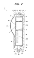
  • Fig. 2 is a sectional view showing the converter for receiving satellite broadcasting according to the present invention; and
  • Fig. 3 is an exploded perspective view showing a conventional type converter for receiving satellite broadcasting.
  • Referring to Figs. 1 and 2, an embodiment of a converter for receiving satellite broadcasting according to the present invention will be described below.
    The converter for receiving satellite broadcasting 1 is composed of first and second cases 2 and 12 mutually combined and integrated and forming a casing, rubber packing 10 as sealing material between the first and second cases 2 and 12 and the body of the converter housed inside the first and second cases 2 and 12.
    The first case 2 is acquired by forming synthetic resin material in the shape of a square box, is provided with an upper wall 3, a lower wall 4 and side walls 5, 6 and 7 and a groove 8 is formed on the end face of the upper and lower walls 3 and 4 and side walls 5, 6 and 7. A semicircular cut-out 4a is formed on the lower wall 4 and a fitting concave portion 9 is formed on each inner wall of the upper and lower walls 3 and 4 and side walls 5 and 7 except the cut-out 4a.
    The rubber packing 10 is acquired by forming rubber material in a rectangle, a part of a lower side 11 is cut and a cut-out 11a is formed. The rubber packing 10 is fitted into the groove 8 of the first case 2 in a state in which the cut-out lla corresponds to the cut-out 4a of the first case 2.
    The second case 12 is acquired by forming synthetic resin material in a rectangle, has its upper and lower walls 13 and 14 and its side walls 15, 16 and 17 and a circular thin part 16a swelling outside is formed on the side wall 16. A semicircular cut-out 14a is formed on the lower wall 14 and a hook 18 is provided to the upper, lower and side walls 13, 14, 15 and 17 except the above cut-out 14a. The second case 12 is combined and integrated with the first case 2 by fitting the hook 18 into the fitting concave portion 9, the cut-out 14a corresponds to the cut-out 4a of the first case 2 and each end face of the upper, lower and side walls 13, 14, 15 and 17 is pressed upon the rubber packing 11.
    The above body of the converter is composed by integrating a printed circuit board 19 made of synthetic resin, a metal frame 24 for attaching the printed circuit board 19 and a metal cover 34 attached to the metal frame 24.
    Copper foil 20 having a rectangular cut-out 20a is formed on one surface of the printed circuit board 19 and four patch antennas 21 made of copper foil as an antenna member are provided in the cut-out 20 by printing, etching and others. A circuit 22 provided with an electric element such as a resistor and a capacitor is formed on the other surface of the printed circuit board 19, and the circuit 22 and each patch antenna 21 are connected via a through hole not shown. Fitting cut-outs 23 are formed at right and left edges of the printed circuit board 19.
    The metal frame 24 is formed by sheet metal having conductivity such as an iron flat plate in a rectangular frame, has an upper plate 25, a lower plate 26 and side plates 27 and 28 and a fitting protrusion 29 is formed on one end face of the side plates 27 and 28. The metal frame 24 is divided into plural parts by a coupling plate 30 for coupling the upper plate 25 and the side plates 27 and 28 and a coupling plate 31 for coupling the lower plate 26 and the side plates 27 and 28. Also, a coaxial line 32 is supported by the lower plate 26 and ringed rubber packing 33 as a sealing member is fitted around the coaxial line 32. The printed circuit board 19 is attached to one end face of the metal frame 24 in a state in which the fitting protrusion 29 is fitted into the fitting cut-out 23, the coaxial line 32 is connected to the circuit 22 and the patch antennas 21 are exposed outside the metal frame 24.
    The metal cover 34 is formed by sheet metal having conductivity such as an iron flat plate in a rectangular box and has an upper plate 35, a lower plate 36 and side plates 37, 38 and 39. The metal cover 34 is attached to the other end face of the metal frame 24 by suitable means such as soldering and caulking and each other end face of the upper and lower plates 25 and 26 and the side plates 27 and 28 of the metal frame 24 is located inside the metal cover.
    Next, to explain a method of assembling the converter for receiving satellite broadcasting 1 composed as described above, first, the fitting cut-out 23 is fitted to the fitting protrusion 29, the printed circuit board 19 on which the copper foil 20, the patch antennas 21 and the circuit 22 are formed is attached to one end face of the metal frame 24 and the coaxial line 32 supported by the lower plate 26 of the metal frame 24 and the circuit 22 are connected by soldering. Next, the rubber packing 33 is fitted around the coaxial line 32, next, each other end face of the upper, lower and side plates 25, 26, 27 and 28 of the metal frame 24 is located inside the metal cover 34, the metal cover 34 is attached to the other end face of the metal frame 24 by suitable means such as soldering and caulking and the assembly of the body of the converter is completed.
    Next, the rubber packing 10 is fitted into the groove 8 of the first case 2, corresponding the cut-outs lla and 4a, next, the body of the converter is housed in the first case 2, the rubber packing 33 is loaded onto the cut-out 4a and the coaxial line 32 is protruded from the first case 2. Afterward, when the second case 12 is combined with the first case 2, corresponding the cut-outs 14a and 4a, at first the end of the hook 18 comes in contact with each end face of the upper, lower and side walls 3, 4, 5 and 7 of the first case 2, when the second case 12 is further pushed in this state, the hook 18 bends inside by the elasticity of the second case 12, when the end of the hook 18 is located in the fitting concave portion 9, the hook 18 is restored in the original state, the hook 18 is latched in the fitting concave portion 9 and the first and second cases 2 and 12 are combined and integrated.
    The assembly of the converter for receiving satellite broadcasting 1 is completed as described above, after the assembly, the body of the converter is housed in the first and second cases 2 and 12, the patch antennas 21 are opposed to the thin part 16a of the second case 12, each end face of the upper, lower and side walls 13, 14, 15 and 17 of the second case 12 is pressed upon the rubber packing 10, the cut-out 14a is pressed upon the rubber packing 33, the rubber packings 10 and 33 are compressed and the inside of the first and second cases 2 and 12 is sealed.
    The converter for receiving satellite broadcasting 1 assembled as described above is attached to the dished parabolic reflector not shown, a radio wave from a satellite is transmitted in the thin part 16a of the second case 12 via the above parabolic reflector, is received by the patch antennas 21, a received signal acquired as described above is amplified and the frequency is converted respectively by the circuit 22, is output from the coaxial line 32 and is input to a receiver not shown of a television set, a video tape recorder and others.
    As the whole periphery of the circuit 22 is covered with the copper foil 22 formed on one surface of the printed circuit board 19, the metal frame 24 and the metal cover 34, noise from the outside of the converter for receiving satellite broadcasting 1 can be intercepted, and stable and precise operation is enabled without being influenced by the outside noise.
    As the printed circuit board and the antenna member provided to the printed circuit board for receiving a radio wave from a satellite via the parabolic reflector are provided, the antenna member is composed of patch antennas made of conductive foil and is formed on one surface of the printed circuit board, a radio wave from a satellite can be received without using a die-cast frame and the converter for receiving satellite broadcasting wherein the cost can be reduced can be provided. In this case, when printing and etching are used in forming the antenna member, the antenna member can be simply formed on the printed board and it is effective to reduce the cost.
    If the metal frame for attaching the printed circuit board and the metal cover attached to the metal frame are provided, the printed circuit board is attached to one end face of the metal frame in a state in which the antenna member is exposed outside, the metal cover is attached to the other end face of the metal frame, and the printed circuit board, the metal frame and the metal cover are integrated, the printed circuit board, the metal frame and the metal cover can be treated as one part in a process for assembling the converter for receiving satellite broadcasting and as they become easy to treat, the productivity can be enhanced.
    Further, if the first and second cases made of synthetic resin respectively combined, integrated and forming a casing are provided, the thin part is formed in the second case, the printed circuit board, the metal frame and the metal cover are housed in the first and second cases, the antenna member and the thin part are opposed, the inside of the first and second cases is sealed, the antenna member can receive a radio wave from a satellite via the thin part, the sensitivity for receiving of the antenna member can be enhanced, a foreign matter such as dust and a water drop can be prevented from invading into the first and second cases and the antenna member can stably and precisely receive a radio wave from a satellite without being influenced by such a foreign matter.
    Claims (3)

    1. A converter for receiving satellite broadcasting, wherein:
      a printed circuit board and an antenna member provided to the printed circuit board for receiving a radio wave from a satellite via a parabolic reflector are provided;
      said antenna member is composed of plural patch antennas made of conductive foil; and
      said antenna member is formed on one surface of said printed circuit board.
    2. The converter for receiving satellite broadcasting according to Claim 1, wherein:
      a metal frame for attaching said printed circuit board and a metal cover attached to the metal frame are provided;
      said printed circuit board is attached to one end face of said metal frame with said antenna member exposed outside;
      said metal cover is attached to the other end face of said metal frame; and
      said printed circuit board, said metal frame and said metal cover are integrated.
    3. The converter for receiving satellite broadcasting according to Claim 1 or 2, wherein:
      first and second cases respectively made of synthetic resin mutually combined, integrated and forming a casing are provided;
      a thin part is formed in the second case;
      said printed circuit board, said metal frame and said metal cover are housed in said first and second cases, and said antenna member and said thin part are opposed; and
      the inside of said first and second cases is sealed.
    EP00301243A 1999-03-04 2000-02-17 Converter provided with built-in patch antennas for receiving direct broadcasting by satellite Withdrawn EP1033779A3 (en)

    Applications Claiming Priority (2)

    Application Number Priority Date Filing Date Title
    JP05715099A JP3626618B2 (en) 1999-03-04 1999-03-04 Converter for satellite broadcasting reception
    JP5715099 1999-03-04

    Publications (2)

    Publication Number Publication Date
    EP1033779A2 true EP1033779A2 (en) 2000-09-06
    EP1033779A3 EP1033779A3 (en) 2004-01-07

    Family

    ID=13047552

    Family Applications (1)

    Application Number Title Priority Date Filing Date
    EP00301243A Withdrawn EP1033779A3 (en) 1999-03-04 2000-02-17 Converter provided with built-in patch antennas for receiving direct broadcasting by satellite

    Country Status (5)

    Country Link
    EP (1) EP1033779A3 (en)
    JP (1) JP3626618B2 (en)
    KR (1) KR100342778B1 (en)
    CN (1) CN1186854C (en)
    TW (1) TW447172B (en)

    Cited By (9)

    * Cited by examiner, † Cited by third party
    Publication number Priority date Publication date Assignee Title
    EP1132997A1 (en) * 2000-03-09 2001-09-12 Lucent Technologies Inc. Sheet-metal antenna
    EP1519443A1 (en) * 2003-09-29 2005-03-30 Mitsumi Electric Co., Ltd. Antenna device
    EP1633015A1 (en) * 2004-09-01 2006-03-08 Alps Electric Co., Ltd. Sealing member and sealing structure of electronic circuit unit
    US7129906B2 (en) * 2003-09-29 2006-10-31 Mitsumi Electric Co., Ltd. Antenna device
    USD543975S1 (en) 2006-08-15 2007-06-05 Mccown James Charles Parabolic antenna
    US7800551B2 (en) 2006-06-27 2010-09-21 Mccown James Charles Passive parabolic antenna, wireless communication system and method of boosting signal strength of a subscriber module antenna
    US9595760B2 (en) 2013-06-07 2017-03-14 James Charles McCown Antenna focusing ring
    CN108987944A (en) * 2018-07-24 2018-12-11 维沃移动通信有限公司 A kind of terminal device
    US11962066B2 (en) 2018-07-24 2024-04-16 Vivo Mobile Communication Co., Ltd. Terminal device

    Families Citing this family (2)

    * Cited by examiner, † Cited by third party
    Publication number Priority date Publication date Assignee Title
    CN104241808B (en) * 2013-06-07 2017-06-30 台达电子工业股份有限公司 Antenna Module and Electronic System
    CN105634248A (en) * 2016-01-14 2016-06-01 天津普传控制设备有限公司 Frequency converter suitable for high-temperature environment

    Family Cites Families (10)

    * Cited by examiner, † Cited by third party
    Publication number Priority date Publication date Assignee Title
    JPH0239122B2 (en) * 1987-07-15 1990-09-04 Matsushita Electric Works Ltd EISEIHOSOJUSHINYOHEIMENANTENA
    US5142698A (en) * 1988-06-08 1992-08-25 Nec Corporation Microwave integrated apparatus including antenna pattern for satellite broadcasting receiver
    JPH03120113U (en) * 1990-03-22 1991-12-10
    US5381157A (en) * 1991-05-02 1995-01-10 Sumitomo Electric Industries, Ltd. Monolithic microwave integrated circuit receiving device having a space between antenna element and substrate
    JPH0677724A (en) * 1992-08-25 1994-03-18 Matsushita Electric Ind Co Ltd Plane patch antenna and its characteristic adjusting method
    KR960011413B1 (en) * 1994-04-30 1996-08-22 대우전자 주식회사 Low noise block down converter
    KR960003078A (en) * 1994-06-30 1996-01-26 배순훈 Receive Converter for Satellite Broadcasting
    GB2296385A (en) * 1994-12-20 1996-06-26 Northern Telecom Ltd Antenna
    US5625365A (en) * 1995-03-10 1997-04-29 Trimble Navigation Limited Dual-frequency microwave radio antenna system
    JPH10145144A (en) * 1996-11-14 1998-05-29 Toshiba Corp Wireless receiver

    Cited By (14)

    * Cited by examiner, † Cited by third party
    Publication number Priority date Publication date Assignee Title
    US6326920B1 (en) 2000-03-09 2001-12-04 Avaya Technology Corp. Sheet-metal antenna
    EP1132997A1 (en) * 2000-03-09 2001-09-12 Lucent Technologies Inc. Sheet-metal antenna
    US7528793B2 (en) 2003-09-29 2009-05-05 Mitsumi Electric Co., Ltd. Antenna device
    EP1519443A1 (en) * 2003-09-29 2005-03-30 Mitsumi Electric Co., Ltd. Antenna device
    US7068238B2 (en) 2003-09-29 2006-06-27 Mitsumi Electric Co., Ltd. Antenna device
    US7129906B2 (en) * 2003-09-29 2006-10-31 Mitsumi Electric Co., Ltd. Antenna device
    EP1633015A1 (en) * 2004-09-01 2006-03-08 Alps Electric Co., Ltd. Sealing member and sealing structure of electronic circuit unit
    US8085214B2 (en) 2006-06-27 2011-12-27 Mccown James Charles Passive parabolic antenna, wireless communication system and method of boosting signal strength of a subscriber module antenna
    US7800551B2 (en) 2006-06-27 2010-09-21 Mccown James Charles Passive parabolic antenna, wireless communication system and method of boosting signal strength of a subscriber module antenna
    USD543975S1 (en) 2006-08-15 2007-06-05 Mccown James Charles Parabolic antenna
    US9595760B2 (en) 2013-06-07 2017-03-14 James Charles McCown Antenna focusing ring
    CN108987944A (en) * 2018-07-24 2018-12-11 维沃移动通信有限公司 A kind of terminal device
    US11527812B2 (en) 2018-07-24 2022-12-13 Vivo Mobile Communication Co., Ltd. Terminal device
    US11962066B2 (en) 2018-07-24 2024-04-16 Vivo Mobile Communication Co., Ltd. Terminal device

    Also Published As

    Publication number Publication date
    TW447172B (en) 2001-07-21
    JP2000261336A (en) 2000-09-22
    EP1033779A3 (en) 2004-01-07
    CN1266293A (en) 2000-09-13
    KR100342778B1 (en) 2002-07-04
    KR20000062726A (en) 2000-10-25
    CN1186854C (en) 2005-01-26
    JP3626618B2 (en) 2005-03-09

    Similar Documents

    Publication Publication Date Title
    JP4235194B2 (en) Antenna unit
    JP4807530B2 (en) Antenna device and antenna waterproof structure
    JP4849281B2 (en) Antenna device
    EP1641074B1 (en) Antenna device
    CN110943277A (en) Antenna device
    JP2005223665A (en) Dielectric resonator and filter device
    JP3626618B2 (en) Converter for satellite broadcasting reception
    EP1633015B1 (en) Sealing member and sealing structure of electronic circuit unit
    EP0632519B1 (en) Mobile communications antenna assembly
    JPH02306562A (en) Tv plug socket
    US7825341B2 (en) Antenna device and shield cover thereof
    KR0143376B1 (en) Horn integrated circular polarization. Linearly polarized transducer
    US7365694B2 (en) Antenna unit which can be designed to be small in size
    JPH05167345A (en) Antenna
    JP2720379B2 (en) Electronic equipment case
    MXPA00002287A (en) Converter provided with built-in patch antennas for receiving direct broadcasting by satellite
    JPH08125404A (en) Circularly polarized primary receiver
    US20100001910A1 (en) On-Vehicle Antenna
    JP2000068722A (en) Multi-frequency antenna
    JP2616200B2 (en) Outdoor communication equipment
    JP2006237813A (en) Patch antenna and antenna unit
    JP3726513B2 (en) GPS receiver
    JP2002043817A (en) Planar antenna and its mounting device
    JPH098535A (en) Loop antenna for mobile radio
    JP2001057507A (en) Converter for satellite reception

    Legal Events

    Date Code Title Description
    PUAI Public reference made under article 153(3) epc to a published international application that has entered the european phase

    Free format text: ORIGINAL CODE: 0009012

    AK Designated contracting states

    Kind code of ref document: A2

    Designated state(s): AT BE CH CY DE DK ES FI FR GB GR IE IT LI LU MC NL PT SE

    AX Request for extension of the european patent

    Free format text: AL;LT;LV;MK;RO;SI

    PUAL Search report despatched

    Free format text: ORIGINAL CODE: 0009013

    AK Designated contracting states

    Kind code of ref document: A3

    Designated state(s): AT BE CH CY DE DK ES FI FR GB GR IE IT LI LU MC NL PT SE

    AX Request for extension of the european patent

    Extension state: AL LT LV MK RO SI

    STAA Information on the status of an ep patent application or granted ep patent

    Free format text: STATUS: THE APPLICATION HAS BEEN WITHDRAWN

    18W Application withdrawn

    Effective date: 20040128