EP1033620A1 - Photographic elements for colorimetrically accurate recording intended for scanning - Google Patents
Photographic elements for colorimetrically accurate recording intended for scanning Download PDFInfo
- Publication number
- EP1033620A1 EP1033620A1 EP00200547A EP00200547A EP1033620A1 EP 1033620 A1 EP1033620 A1 EP 1033620A1 EP 00200547 A EP00200547 A EP 00200547A EP 00200547 A EP00200547 A EP 00200547A EP 1033620 A1 EP1033620 A1 EP 1033620A1
- Authority
- EP
- European Patent Office
- Prior art keywords
- color
- emulsion
- recording
- layer unit
- sensitivity
- Prior art date
- Legal status (The legal status is an assumption and is not a legal conclusion. Google has not performed a legal analysis and makes no representation as to the accuracy of the status listed.)
- Withdrawn
Links
- 239000000839 emulsion Substances 0.000 claims abstract description 288
- 230000035945 sensitivity Effects 0.000 claims abstract description 133
- 239000010410 layer Substances 0.000 claims description 233
- 239000000463 material Substances 0.000 claims description 37
- 239000011229 interlayer Substances 0.000 claims description 21
- 230000000873 masking effect Effects 0.000 claims description 14
- 239000000084 colloidal system Substances 0.000 claims description 9
- 229910052709 silver Inorganic materials 0.000 abstract description 150
- 239000004332 silver Substances 0.000 abstract description 150
- 230000003595 spectral effect Effects 0.000 abstract description 73
- -1 silver halide Chemical class 0.000 abstract description 35
- 238000012545 processing Methods 0.000 abstract description 26
- 239000000975 dye Substances 0.000 description 138
- BQCADISMDOOEFD-UHFFFAOYSA-N Silver Chemical compound [Ag] BQCADISMDOOEFD-UHFFFAOYSA-N 0.000 description 122
- 238000011161 development Methods 0.000 description 58
- 230000004044 response Effects 0.000 description 37
- 230000009102 absorption Effects 0.000 description 36
- 238000010521 absorption reaction Methods 0.000 description 36
- 239000000523 sample Substances 0.000 description 33
- 239000003112 inhibitor Substances 0.000 description 31
- 108010010803 Gelatin Proteins 0.000 description 29
- 229920000159 gelatin Polymers 0.000 description 29
- 239000008273 gelatin Substances 0.000 description 29
- 235000019322 gelatine Nutrition 0.000 description 29
- 235000011852 gelatine desserts Nutrition 0.000 description 29
- XMBWDFGMSWQBCA-UHFFFAOYSA-N hydrogen iodide Chemical compound I XMBWDFGMSWQBCA-UHFFFAOYSA-N 0.000 description 23
- ZUNKMNLKJXRCDM-UHFFFAOYSA-N silver bromoiodide Chemical compound [Ag].IBr ZUNKMNLKJXRCDM-UHFFFAOYSA-N 0.000 description 21
- 238000011160 research Methods 0.000 description 17
- 239000002516 radical scavenger Substances 0.000 description 16
- 239000003795 chemical substances by application Substances 0.000 description 15
- 239000007844 bleaching agent Substances 0.000 description 14
- 239000011248 coating agent Substances 0.000 description 14
- 238000000576 coating method Methods 0.000 description 14
- 238000000034 method Methods 0.000 description 14
- NINIDFKCEFEMDL-UHFFFAOYSA-N Sulfur Chemical compound [S] NINIDFKCEFEMDL-UHFFFAOYSA-N 0.000 description 12
- PCHJSUWPFVWCPO-UHFFFAOYSA-N gold Chemical compound [Au] PCHJSUWPFVWCPO-UHFFFAOYSA-N 0.000 description 12
- 229910052737 gold Inorganic materials 0.000 description 12
- 239000010931 gold Substances 0.000 description 12
- 239000003381 stabilizer Substances 0.000 description 12
- 229910052717 sulfur Inorganic materials 0.000 description 12
- 239000011593 sulfur Substances 0.000 description 12
- 230000000052 comparative effect Effects 0.000 description 11
- 238000000326 densiometry Methods 0.000 description 11
- 230000003287 optical effect Effects 0.000 description 11
- 230000001235 sensitizing effect Effects 0.000 description 11
- 238000010276 construction Methods 0.000 description 10
- 230000006870 function Effects 0.000 description 10
- 230000031700 light absorption Effects 0.000 description 10
- 239000000126 substance Substances 0.000 description 10
- 238000012546 transfer Methods 0.000 description 10
- 230000008569 process Effects 0.000 description 9
- 230000005855 radiation Effects 0.000 description 9
- 150000001875 compounds Chemical class 0.000 description 8
- 238000003384 imaging method Methods 0.000 description 7
- 239000000203 mixture Substances 0.000 description 7
- AJDUTMFFZHIJEM-UHFFFAOYSA-N n-(9,10-dioxoanthracen-1-yl)-4-[4-[[4-[4-[(9,10-dioxoanthracen-1-yl)carbamoyl]phenyl]phenyl]diazenyl]phenyl]benzamide Chemical compound O=C1C2=CC=CC=C2C(=O)C2=C1C=CC=C2NC(=O)C(C=C1)=CC=C1C(C=C1)=CC=C1N=NC(C=C1)=CC=C1C(C=C1)=CC=C1C(=O)NC1=CC=CC2=C1C(=O)C1=CC=CC=C1C2=O AJDUTMFFZHIJEM-UHFFFAOYSA-N 0.000 description 7
- 239000001043 yellow dye Substances 0.000 description 7
- 206010070834 Sensitisation Diseases 0.000 description 6
- 230000001447 compensatory effect Effects 0.000 description 6
- 230000000694 effects Effects 0.000 description 6
- 239000003607 modifier Substances 0.000 description 6
- 230000008313 sensitization Effects 0.000 description 6
- 230000003993 interaction Effects 0.000 description 5
- 230000002829 reductive effect Effects 0.000 description 5
- 239000000243 solution Substances 0.000 description 5
- 230000000007 visual effect Effects 0.000 description 5
- CPELXLSAUQHCOX-UHFFFAOYSA-M Bromide Chemical compound [Br-] CPELXLSAUQHCOX-UHFFFAOYSA-M 0.000 description 4
- VEXZGXHMUGYJMC-UHFFFAOYSA-M Chloride anion Chemical compound [Cl-] VEXZGXHMUGYJMC-UHFFFAOYSA-M 0.000 description 4
- 239000011324 bead Substances 0.000 description 4
- 239000003086 colorant Substances 0.000 description 4
- 229920003229 poly(methyl methacrylate) Polymers 0.000 description 4
- 239000004926 polymethyl methacrylate Substances 0.000 description 4
- 230000000717 retained effect Effects 0.000 description 4
- ADZWSOLPGZMUMY-UHFFFAOYSA-M silver bromide Chemical compound [Ag]Br ADZWSOLPGZMUMY-UHFFFAOYSA-M 0.000 description 4
- 238000001228 spectrum Methods 0.000 description 4
- 238000001429 visible spectrum Methods 0.000 description 4
- 241001637516 Polygonia c-album Species 0.000 description 3
- 239000006096 absorbing agent Substances 0.000 description 3
- 239000011358 absorbing material Substances 0.000 description 3
- 230000008901 benefit Effects 0.000 description 3
- 230000015572 biosynthetic process Effects 0.000 description 3
- 238000012822 chemical development Methods 0.000 description 3
- 150000004820 halides Chemical class 0.000 description 3
- 238000010348 incorporation Methods 0.000 description 3
- 239000000314 lubricant Substances 0.000 description 3
- 238000005259 measurement Methods 0.000 description 3
- 230000007935 neutral effect Effects 0.000 description 3
- 239000002344 surface layer Substances 0.000 description 3
- 238000012360 testing method Methods 0.000 description 3
- 230000009466 transformation Effects 0.000 description 3
- XXAXVMUWHZHZMJ-UHFFFAOYSA-L 4,5-dihydroxybenzene-1,3-disulfonate Chemical compound OC1=CC(S([O-])(=O)=O)=CC(S([O-])(=O)=O)=C1O XXAXVMUWHZHZMJ-UHFFFAOYSA-L 0.000 description 2
- 229920002284 Cellulose triacetate Polymers 0.000 description 2
- QXNVGIXVLWOKEQ-UHFFFAOYSA-N Disodium Chemical class [Na][Na] QXNVGIXVLWOKEQ-UHFFFAOYSA-N 0.000 description 2
- 241000483002 Euproctis similis Species 0.000 description 2
- NNLVGZFZQQXQNW-ADJNRHBOSA-N [(2r,3r,4s,5r,6s)-4,5-diacetyloxy-3-[(2s,3r,4s,5r,6r)-3,4,5-triacetyloxy-6-(acetyloxymethyl)oxan-2-yl]oxy-6-[(2r,3r,4s,5r,6s)-4,5,6-triacetyloxy-2-(acetyloxymethyl)oxan-3-yl]oxyoxan-2-yl]methyl acetate Chemical compound O([C@@H]1O[C@@H]([C@H]([C@H](OC(C)=O)[C@H]1OC(C)=O)O[C@H]1[C@@H]([C@@H](OC(C)=O)[C@H](OC(C)=O)[C@@H](COC(C)=O)O1)OC(C)=O)COC(=O)C)[C@@H]1[C@@H](COC(C)=O)O[C@@H](OC(C)=O)[C@H](OC(C)=O)[C@H]1OC(C)=O NNLVGZFZQQXQNW-ADJNRHBOSA-N 0.000 description 2
- SJOOOZPMQAWAOP-UHFFFAOYSA-N [Ag].BrCl Chemical compound [Ag].BrCl SJOOOZPMQAWAOP-UHFFFAOYSA-N 0.000 description 2
- 230000003321 amplification Effects 0.000 description 2
- 239000002216 antistatic agent Substances 0.000 description 2
- 239000003139 biocide Substances 0.000 description 2
- 238000011109 contamination Methods 0.000 description 2
- 238000012937 correction Methods 0.000 description 2
- 239000013078 crystal Substances 0.000 description 2
- 230000006378 damage Effects 0.000 description 2
- DOIRQSBPFJWKBE-UHFFFAOYSA-N dibutyl phthalate Chemical compound CCCCOC(=O)C1=CC=CC=C1C(=O)OCCCC DOIRQSBPFJWKBE-UHFFFAOYSA-N 0.000 description 2
- 238000009792 diffusion process Methods 0.000 description 2
- 238000009826 distribution Methods 0.000 description 2
- 238000001035 drying Methods 0.000 description 2
- 230000000670 limiting effect Effects 0.000 description 2
- 238000004519 manufacturing process Methods 0.000 description 2
- 230000007246 mechanism Effects 0.000 description 2
- 230000004048 modification Effects 0.000 description 2
- 238000012986 modification Methods 0.000 description 2
- 238000003199 nucleic acid amplification method Methods 0.000 description 2
- 239000004848 polyfunctional curative Substances 0.000 description 2
- 229920001296 polysiloxane Polymers 0.000 description 2
- 230000001681 protective effect Effects 0.000 description 2
- 238000000926 separation method Methods 0.000 description 2
- 239000004094 surface-active agent Substances 0.000 description 2
- IJHIIHORMWQZRQ-UHFFFAOYSA-N 1-(ethenylsulfonylmethylsulfonyl)ethene Chemical compound C=CS(=O)(=O)CS(=O)(=O)C=C IJHIIHORMWQZRQ-UHFFFAOYSA-N 0.000 description 1
- JAAIPIWKKXCNOC-UHFFFAOYSA-N 1h-tetrazol-1-ium-5-thiolate Chemical compound SC1=NN=NN1 JAAIPIWKKXCNOC-UHFFFAOYSA-N 0.000 description 1
- OBETXYAYXDNJHR-UHFFFAOYSA-N 2-Ethylhexanoic acid Chemical compound CCCCC(CC)C(O)=O OBETXYAYXDNJHR-UHFFFAOYSA-N 0.000 description 1
- PYGXAGIECVVIOZ-UHFFFAOYSA-N Dibutyl decanedioate Chemical compound CCCCOC(=O)CCCCCCCCC(=O)OCCCC PYGXAGIECVVIOZ-UHFFFAOYSA-N 0.000 description 1
- CWNSVVHTTQBGQB-UHFFFAOYSA-N N,N-Diethyldodecanamide Chemical compound CCCCCCCCCCCC(=O)N(CC)CC CWNSVVHTTQBGQB-UHFFFAOYSA-N 0.000 description 1
- 206010034960 Photophobia Diseases 0.000 description 1
- 229910021607 Silver chloride Inorganic materials 0.000 description 1
- YSMRWXYRXBRSND-UHFFFAOYSA-N TOTP Chemical compound CC1=CC=CC=C1OP(=O)(OC=1C(=CC=CC=1)C)OC1=CC=CC=C1C YSMRWXYRXBRSND-UHFFFAOYSA-N 0.000 description 1
- GTVWRXDRKAHEAD-UHFFFAOYSA-N Tris(2-ethylhexyl) phosphate Chemical compound CCCCC(CC)COP(=O)(OCC(CC)CCCC)OCC(CC)CCCC GTVWRXDRKAHEAD-UHFFFAOYSA-N 0.000 description 1
- 241000677635 Tuxedo Species 0.000 description 1
- HOLVRJRSWZOAJU-UHFFFAOYSA-N [Ag].ICl Chemical compound [Ag].ICl HOLVRJRSWZOAJU-UHFFFAOYSA-N 0.000 description 1
- 239000003513 alkali Substances 0.000 description 1
- 238000003491 array Methods 0.000 description 1
- 230000001174 ascending effect Effects 0.000 description 1
- 230000004888 barrier function Effects 0.000 description 1
- 230000005540 biological transmission Effects 0.000 description 1
- 239000006227 byproduct Substances 0.000 description 1
- SHZIWNPUGXLXDT-UHFFFAOYSA-N caproic acid ethyl ester Natural products CCCCCC(=O)OCC SHZIWNPUGXLXDT-UHFFFAOYSA-N 0.000 description 1
- 238000006243 chemical reaction Methods 0.000 description 1
- 238000004737 colorimetric analysis Methods 0.000 description 1
- 239000000470 constituent Substances 0.000 description 1
- 239000013068 control sample Substances 0.000 description 1
- 230000007812 deficiency Effects 0.000 description 1
- 230000002939 deleterious effect Effects 0.000 description 1
- 238000001739 density measurement Methods 0.000 description 1
- 238000000586 desensitisation Methods 0.000 description 1
- 230000004069 differentiation Effects 0.000 description 1
- 230000009365 direct transmission Effects 0.000 description 1
- 238000001914 filtration Methods 0.000 description 1
- 230000006872 improvement Effects 0.000 description 1
- 230000001788 irregular Effects 0.000 description 1
- 238000002955 isolation Methods 0.000 description 1
- 208000013469 light sensitivity Diseases 0.000 description 1
- 239000006249 magnetic particle Substances 0.000 description 1
- 239000011159 matrix material Substances 0.000 description 1
- 239000006224 matting agent Substances 0.000 description 1
- 238000002156 mixing Methods 0.000 description 1
- ZWDZJRRQSXLOQR-UHFFFAOYSA-N n-butyl-n-phenylacetamide Chemical compound CCCCN(C(C)=O)C1=CC=CC=C1 ZWDZJRRQSXLOQR-UHFFFAOYSA-N 0.000 description 1
- 230000008520 organization Effects 0.000 description 1
- 230000033116 oxidation-reduction process Effects 0.000 description 1
- 239000002245 particle Substances 0.000 description 1
- 230000000704 physical effect Effects 0.000 description 1
- 239000000049 pigment Substances 0.000 description 1
- 239000004014 plasticizer Substances 0.000 description 1
- 229920000642 polymer Polymers 0.000 description 1
- 239000002243 precursor Substances 0.000 description 1
- 238000002360 preparation method Methods 0.000 description 1
- 230000002265 prevention Effects 0.000 description 1
- 239000011241 protective layer Substances 0.000 description 1
- 238000001454 recorded image Methods 0.000 description 1
- 238000006479 redox reaction Methods 0.000 description 1
- 230000009467 reduction Effects 0.000 description 1
- HKZLPVFGJNLROG-UHFFFAOYSA-M silver monochloride Chemical compound [Cl-].[Ag+] HKZLPVFGJNLROG-UHFFFAOYSA-M 0.000 description 1
- 239000002356 single layer Substances 0.000 description 1
- 239000002904 solvent Substances 0.000 description 1
- 125000006850 spacer group Chemical group 0.000 description 1
- 230000006641 stabilisation Effects 0.000 description 1
- 238000011105 stabilization Methods 0.000 description 1
- 238000000844 transformation Methods 0.000 description 1
- 230000001131 transforming effect Effects 0.000 description 1
- WFKWXMTUELFFGS-UHFFFAOYSA-N tungsten Chemical compound [W] WFKWXMTUELFFGS-UHFFFAOYSA-N 0.000 description 1
- 229910052721 tungsten Inorganic materials 0.000 description 1
- 239000010937 tungsten Substances 0.000 description 1
- 239000006097 ultraviolet radiation absorber Substances 0.000 description 1
- 238000005406 washing Methods 0.000 description 1
Images



Classifications
-
- G—PHYSICS
- G03—PHOTOGRAPHY; CINEMATOGRAPHY; ANALOGOUS TECHNIQUES USING WAVES OTHER THAN OPTICAL WAVES; ELECTROGRAPHY; HOLOGRAPHY
- G03C—PHOTOSENSITIVE MATERIALS FOR PHOTOGRAPHIC PURPOSES; PHOTOGRAPHIC PROCESSES, e.g. CINE, X-RAY, COLOUR, STEREO-PHOTOGRAPHIC PROCESSES; AUXILIARY PROCESSES IN PHOTOGRAPHY
- G03C7/00—Multicolour photographic processes or agents therefor; Regeneration of such processing agents; Photosensitive materials for multicolour processes
- G03C7/30—Colour processes using colour-coupling substances; Materials therefor; Preparing or processing such materials
- G03C7/3041—Materials with specific sensitometric characteristics, e.g. gamma, density
-
- G—PHYSICS
- G03—PHOTOGRAPHY; CINEMATOGRAPHY; ANALOGOUS TECHNIQUES USING WAVES OTHER THAN OPTICAL WAVES; ELECTROGRAPHY; HOLOGRAPHY
- G03C—PHOTOSENSITIVE MATERIALS FOR PHOTOGRAPHIC PURPOSES; PHOTOGRAPHIC PROCESSES, e.g. CINE, X-RAY, COLOUR, STEREO-PHOTOGRAPHIC PROCESSES; AUXILIARY PROCESSES IN PHOTOGRAPHY
- G03C2200/00—Details
- G03C2200/19—Colour negative
Definitions
- the field of the invention is color photographic films intended to be scanned in order to retrieve the recorded image for viewing.
- the element is particularly suitable for accurately capturing scene light exposures with high colorimetric precision, where image transformation to a viewable form is achieved by film scanning, electronic signal processing, and image file transfer to an output device.
- the halides are named in order of ascending concentrations.
- high chloride and high bromide in referring to grains and emulsions indicate that chloride or bromide, respectively, is present in a concentration of greater than 50 mole percent, based on silver.
- ECD equivalent circular diameter
- tabular grain indicates a grain having two parallel crystal faces which are clearly larger than any remaining crystal faces and an aspect ratio of at least 2.
- tabular grain emulsion refers to an emulsion in which tabular grains account for greater than 50 percent of total grain projected area.
- blue spectral sensitizing dye refers to a dye or combination of dyes that sensitize silver halide grains and, when adsorbed, have their peak absorption in the blue, green and red regions of the spectrum, respectively.
- half-peak bandwidth in referring to a dye indicates the spectral region over which absorption exhibited by the dye is at least half its absorption at its wavelength of maximum absorption.
- layer unit indicates the layer or layers that contain radiation-sensitive silver halide grains to capture exposing radiation and that contain couplers that react upon development of the grains.
- the grains and couplers are usually in the same layer, but can be in adjacent layers.
- all half-peak bandwidth indicates the spectral region over which a combination of spectral sensitizing dyes within a layer unit exhibits absorption that is at least half their combined maximum absorption at any single wavelength.
- die image-forming coupler indicates a coupler that reacts with oxidized color developing agent to produce a dye image.
- colored masking coupler indicates a coupler that is initially colored and that loses its initial color during development upon reaction with oxidized color developing agent.
- substantially free of colored masking coupler indicates a total coating coverage of less than 0.02 millimole/m 2 of colored masking coupler.
- development inhibitor releasing compound indicates a compound that cleaves to release a development inhibitor during color development.
- DIR's include couplers and other compounds that utilize anchimeric and timed releasing mechanisms.
- Status M density indicates density measurements obtained from a densitometer meeting photocell and filter specifications described in SPSE Handbook of Photographic Science and Engineering, W. Thomas, editor, John Wiley & Sons, New York, 1973, Section 15.4.2.6 Color Filters.
- the International Standard for Status M density is set out in "Photography--Density Measurements--Part 3: Spectral conditions", Ref. No. ISO 5/3-1984 (E).
- exposure latitude indicates the exposure range of a characteristic curve segment over which instantaneous gamma ( ⁇ D/ ⁇ log E) is at least 25 percent of gamma, as defined above.
- the exposure latitude of a color element having multiple color recording units is the exposure range over which the characteristic curves of the red, green, and blue color recording units simultaneously fulfill the aforesaid definition.
- gamma ratio when applied to a color recording layer unit refers to the ratio determined by dividing the color gamma of a cited layer unit after an imagewise color separation exposure and process that enables development of primarily that layer unit by the color gamma of the same layer unit after an imagewise white light exposure and process that enables development of all layer units. This term relates to the degree of color saturation available from that layer unit after conventional optical printing. Larger values of the gamma ratio indicate enhanced degrees of color saturation under optical printing conditions.
- Photographic recording materials have historically been designed to operate in an analog world involving direct optical print-through to a reflection print material or direct viewing of transmitted light, depending on the mode of image development.
- Color negative films record scene light exposures and, following development and chemical image processing through interlayer interimage effects generally produced by colored masking couplers and development inhibitor releasing couplers, yield orange masked-films suitable for the attenuation of light to allow the exposure of silver halide color paper giving a viewable representation of the scene after its processing and drying.
- Color reversal films record scene light exposures and, following development and chemical image processing through interlayer interimage effects generally produced by first development iodide gradients and second development inhibitor releasing couplers, yield positive images suitable for projection and viewing in a dark surround.
- the accuracy of recording the different colors of visible light in the scene exposures is limited by either the constituents the films were required to contain to perform their function (e.g. colored masking couplers in color negative films) or the degree of chemical image processing achievable for color correction or 'management' by chemical development modification.
- the color films can be re-designed to record scene exposures with greater accuracy. More accurate color recording of the scene light is in fact vital to obtain the full benefit of such hybrid systems.
- the unique non-linear signal amplifications available to electronic image processsing can produce a multitude of different high quality renditions of the scene, depending on individual preferences, but these renditions will be unfaithful in their color rendition and disappointing, if the color film failed to record the scene exposures correctly at the time of photography.
- Such color accuracy requirements are found in metameric color failure, where the certain objects with very different spectral reflectance properties stimulate the human visual system sensitivities the same.
- optical color film spectral sensitivities differ from that of the eye, theses films record the scene exposures differently leading to color recording errors.
- certain artificial illuminants such as inexpensive fluorescent lights
- closely spaced line emissions by the tube phosphors correctly stimulate the overlapping eye RGB channels to produce the appearance of neutral white light, and nearly normal white light colors of viewed objects or subjects results.
- the non-overlapping spectral sensitivities of color films result in relatively large color recording gaps, and inaccurate color rendition the same objects or subjects inevitably results.
- Color films designed for scanning and electronic processing of the image-bearing signals can benefit from silver halide emulsion spectral sensitivity that is more colorimetrically accurate.
- the cyan dye image-forming layer contain at least one light sensitive silver halide emulsion with a maximum sensitivity greater than 603 nm.
- the red recording unit is comprised of a magenta colored filter dye material which absorbs visible radiation shorter than the maximum sensitivity of said cyan-dye forming unit. Adequate red recording unit hypsochromic sensitivity for optimal colorimetrically accurate capture is not provided in the presence of the magenta trimmer dye filtering the scene exposures incident on it.
- Giorgianni et al demonstrate color reversal films with red recording unit maximum sensitivity around 600 nm, with broad half-peak bandwidth relative sensitivity in the same red unit, and with substantially overlapping green and red recording silver halide emulsion unit spectral sensitivity.
- the green recording silver halide emulsion unit 50%-maximum peak bandwidth spans only 60 nm , and sensitivity at 520 nm in the hypsochromic, shorter green region is 53% of the maximum relative sensitivity.
- the blue recording silver halide unit maximum sensitivity is found at 422 nm, contributing to reduced blue and green recording unit overlapping sensitivity. In aggregate, the colorimetric accuracy of the element was handicapped by these flaws.
- the photographic element red and green sensitivity must meet certain requirements provided by dyed silver halide emulsions.
- the green and red maximum sensitivities must fall somewhat more hypsochromic of their usual positions in films designed for direct optical printing or viewing.
- the green record sensitivity must be broad, with substantial relative short green responsivity. The need for high color accuracy recording by a silver halide emulsion-based image capture element that provides the colorimetry of scene exposures remains unsatisfied .
- the present invention can be viewed as an improvement on teachings of Buitano et al in that it has been discovered that improved color capture accuracy can be achieved when the green unit spectral relative spectral sensitivity at 520 nm is at least 60% of the maximum sensitivity.
- this invention is directed to a color photographic element capable of producing dye images suitable for digital scanning comprised of:
- a typical color negative film construction useful in the practice of the invention is illustrated by the following: Element SCN-1 SOC Surface Overcoat BU Blue Recording Layer Unit IL1 First Interlayer GU Green Recording Layer Unit IL2 Second Interlayer RU Red Recording Layer Unit AHU Antihalation Layer Unit S Support SOC Surface Overcoat
- the support S can be either reflective or transparent, which is usually preferred. When reflective, the support is white and can take the form of any conventional support currently employed in color print elements. When the support is transparent, it can be colorless or tinted and can take the form of any conventional support currently employed in color negative elements ⁇ e.g., a colorless or tinted transparent film support. Details of support construction are well understood in the art.
- the element can contain additional layers, such as filter layers, interlayers, overcoat layers, subbing layers, or antihalation layers. Transparent and reflective support constructions, including subbing layers to enhance adhesion, are disclosed in Research Disclosure, Item 38957, cited above, XV. Supports.
- Photographic elements of the present invention may also usefully include a magnetic recording material as described in Research Disclosure, Item 34390, November 1992, or a transparent magnetic recording layer such as a layer containing magnetic particles on the underside of a transparent support as in US Patent No. 4,279,945, and US Pat. No. 4,302,523.
- Each of blue, green and red recording layer units BU , GU and RU are formed of one or more hydrophilic colloid layers and contain at least one radiation-sensitive silver halide emulsion and coupler, including at least one dye image-forming coupler. It is preferred that the green, and red recording units are subdivided into at least two recording layer sub-units to provide increased recording latitude and reduced image granularity. In the simplest contemplated construction each of the layer units or layer sub-units consists of a single hydrophilic colloid layer containing emulsion and coupler.
- the coupler containing hydrophilic colloid layer is positioned to receive oxidized color developing agent from the emulsion during development.
- the coupler containing layer is the next adjacent hydrophilic colloid layer to the emulsion containing layer.
- all of the sensitized layers are preferably positioned on a common face of the support.
- the element When in spool form, the element will be spooled such that when unspooled in a camera, exposing light strikes all of the sensitized layers before striking the face of the support carrying these layers.
- the total thickness of the layer units above the support should be controlled. Generally, the total thickness of the sensitized layers, interlayers and protective layers on the exposure face of the support are less than 35 ⁇ m.
- the total layer thickness be less than 28 ⁇ m, more preferred that the total layer thickness be less than 22 ⁇ m, and most preferred that the total layer thickness be less than 17 ⁇ m.
- This constraint on total layer thickness is enabled by controlling the total quantity light sensitive silver halide as described below, and by controlling the total quantity of vehicle and other components, such as couplers, solvent, and such in the layers.
- the total quantity of vehicle is generally less than 20 g/m 2 , preferably less than 14 g/m 2 , and more preferably less than 10 g/m 2 .
- at least 3 g/m 2 of vehicle, and preferably at least 5 g/m 2 of vehicle is present so as to ensure adhesion of the layers to the support during processing and proper isolation of the layer components.
- the total quantity of other components is generally less than 12 g/m 2 , preferably less than 8 g/m 2 , and more preferably less than 5 g/m 2 .
- the emulsion in BU is capable of forming a latent image when exposed to blue light.
- the emulsion contains high bromide silver halide grains and particularly when minor (0.5 to 20, preferably 1 to 10, mole percent, based on silver) amounts of iodide are also present in the radiation-sensitive grains, the native sensitivity of the grains can be relied upon for absorption of blue light.
- the emulsion is spectrally sensitized with two or more blue spectral sensitizing dyes to achieve the required absorption breadth of color matching function spectral sensitivity which mimics human visual sensitivity. Tabular emulsions are preferred for providing dyed blue spectral sensitivity.
- the emulsions in GU and RU are spectrally sensitized with green and red spectral sensitizing dyes, respectively, in all instances, since silver halide emulsions have no native sensitivity to green and/or red (minus blue) light.
- the red unit emulsions of the invention preferably are comprised of at least four spectral sensitizing dyes. More preferably, at least five spectral sensitizing dyes are employed to achieve the required spectral breadth of responsivity to green-red light.
- any convenient selection from among conventional radiation-sensitive silver halide emulsions can be incorporated within the layer units and used to provide the spectral absorptances of the invention. Most commonly high bromide emulsions containing a minor amount of iodide are employed. To realize higher rates of processing, high chloride emulsions can be employed. Radiation-sensitive silver chloride, silver bromide, silver iodobromide, silver iodochloride, silver chlorobromide, silver bromochloride, silver iodochlorobromide and silver iodobromochloride grains are all contemplated. The grains can be either regular or irregular (e.g., tabular).
- Tabular grain emulsions those in which tabular grains account for at least 50 (preferably at least 70 and optimally at least 90) percent of total grain projected area are particularly advantageous for increasing speed in relation to granularity.
- a grain requires two major parallel faces with a ratio of its equivalent circular diameter (ECD) to its thickness of at least 2.
- ECD equivalent circular diameter
- Specifically preferred tabular grain emulsions are those having a tabular grain average aspect ratio of at least 5 and, optimally, greater than 8.
- Preferred mean tabular grain thicknesses are less than 0.3 ⁇ m (most preferably less than 0.2 ⁇ m).
- Ultrathin tabular grain emulsions those with mean tabular grain thicknesses of less than 0.07 ⁇ m, are specifically preferred for the blue sensitive recording unit.
- the green sensitive recording unit is preferably comprised of tabular grains with an aspect ratio of less than or equal to 15.
- the grains preferably form surface latent images so that they produce negative images when processed in a surface developer in color negative film forms of the
- the total quantity be less than 10 g/m 2 of silver.
- Silver quantities of less than 7 g/m 2 are preferred, and silver quantities of less than 5 g/m 2 are even more preferred.
- the lower quantities of silver improve the optics of the elements, thus enabling the production of sharper pictures using the elements.
- These lower quantities of silver are additionally important in that they enable rapid development and desilvering of the elements.
- a silver coating coverage of at least 2 g of coated silver per m 2 of support surface area in the element is necessary to realize an exposure latitude of at least 2.7 log E while maintaining an adequately low graininess position for pictures intended to be enlarged.
- the green light recording layer unit is preferred to have a coated silver coverage of at least 0.8 g/m 2 . It is more preferred that the red and green units together have at least 1.7 g/m 2 of coated silver and even more preferred that each of the red, green, and blue color units has at least 0.8 g/m 2 of coated silver. Because of its less favored location for processing, it is generally preferred that the layer unit located, on average, closest to the support contain a silver coating coverage of at least 1.0 g/m 2 of coated silver. Typically, this is the red recording layer unit. For many photographic applications, optimum silver coverages are at least 0.9 g/m 2 in the blue recording layer unit and at least 1.5 g/m 2 in the green and red recording layer units.
- BU contains at least one yellow dye image-forming coupler
- GU contains at least one magenta dye image-forming coupler
- RU contains at least one cyan dye image-forming coupler. Any convenient combination of conventional dye image-forming couplers can be employed. Conventional dye image-forming couplers are illustrated by Research Disclosure , Item 38957, cited above, X. Dye image formers and modifiers, B. Image-dye-forming couplers. Magenta colored masking couplers are absent from RU.
- the invention is applicable to conventional color negative film or color reversal film constructions.
- the spectral sensitivities can also be employed in photothermographic elements, and in particular, camera speed photothermographic elements as known in the art.
- Specific examples of multicolor photothermographic elements are described by Levy et al. In United States Patent Application Serial Number 08/740,110, filed 28 October 1996, by Ishikawa et al in European Patent Application EP 0, 762,201 A1, and by Asami in US Patent 5,573,560, the disclosures of which are both incorporated by reference.
- the invention is also applicable to image transfer photothermographic elements such as disclosed in Ishikawa et al European Patent Application EP 0 800 114 A2.
- RU , GU and BU are each substantially free of colored masking coupler.
- the layer units each contain less than 0.02 (most preferably less than 0.01) millimole/m 2 of colored masking coupler. No colored masking coupler is required in the color negative elements of this invention.
- Development inhibitor releasing compound is incorporated in at least one and, preferably, each of the layer units in color negative film forms of the invention.
- DIR's are commonly employed to improve image sharpness and to tailor dye image characteristic curve shapes.
- the DIR's contemplated for incorporation in the color negative elements of the invention can release development inhibitor moieties directly or through intermediate linking or timing groups.
- the DIR's are contemplated to include those that employ anchimeric releasing mechanisms. Illustrations of development inhibitor releasing couplers and other compounds useful in the color negative elements of this invention are provided by Research Disclosure , Item 38957, cited above, X. Dye image formers and modifiers, C. Image dye modifiers, particularly paragraphs (4) to (11).
- One or more of the layer units of the invention is preferably subdivided into at least two, and more preferably three or more sub-unit layers. It is preferred that all light sensitive silver halide emulsions in the color recording unit have spectral sensitivity in the same region of the visible spectrum. In this embodiment, while all silver halide emulsions incorporated in the unit have spectral absorptance according to invention, it is expected that there are minor differences in spectral absorptance properties between them.
- the sensitizations of the slower silver halide emulsions are specifically tailored to account for the light shielding effects of the faster silver halide emulsions of the layer unit that reside above them, in order to provide an imagewise uniform spectral response by the photographic recording material as exposure varies with low to high light levels.
- higher proportions of peak light absorbing spectral sensitizing dyes may be desirable in the slower emulsions of the subdivided layer unit to account for on-peak shielding and broadening of the underlying layer spectral sensitivity.
- the interlayers IL1 and IL2 are hydrophilic colloid layers having as their primary function color contamination reduction ⁇ i.e., prevention of oxidized developing agent from migrating to an adjacent recording layer unit before reacting with dye-forming coupler.
- the interlayers are in part effective simply by increasing the diffusion path length that oxidized developing agent must travel.
- Antistain agents oxidized developing agent scavengers
- a yellow filter such as Carey Lea silver or a yellow processing solution decolorizable dye
- Suitable yellow filter dyes can be selected from among those illustrated by Research Disclosure, Item 38957, VIII. Absorbing and scattering materials, B. Absorbing materials. In elements of the instant invention, magenta colored filter materials we absent fro m IL2 and RU .
- the antihalation layer unit AHU typically contains a processing solution removable or decolorizable light absorbing material, such as one or a combination of pigments and dyes. Suitable materials can be selected from among those disclosed in Research Disclosure, Item 38957, VIII. Absorbing materials.
- a common alternative location for AHU is between the support S and the recording layer unit coated newest the support.
- the surface overcoats SOC we hydrophilic colloid layers that are provided for physical protection of the color negative elements during handling and processing.
- Each SOC also provides a convenient location for incorporation of addenda that we most effective at or new the surface of the color negative element.
- the surface overcoat is divided into a surface layer and an interlayer, the latter functioning as spacer between the addenda in the surface layer and the adjacent recording layer unit.
- addenda we distributed between the surface layer and the interlayer, with the latter containing addenda that are compatible with the adjacent recording layer unit.
- the SOC contains addenda, such as coating aids, plasticizers and lubricants, antistats and matting agents, such as illustrated by Research Disclosure, Item 38957, IX.
- the SOC overlying the emulsion layers additionally preferably contains an ultraviolet absorber, such as illustrated by Research Disclosure , Item 38957, VI. UV dyes/optical brighteners/luminescent dyes, paragraph (1).
- layer unit sequence of element SCN-1 instead of the layer unit sequence of element SCN-1 , alternative layer units sequences can be employed and are particularly attractive for some emulsion choices.
- high chloride emulsions and/or thin ( ⁇ 0.2 ⁇ m mean grain thickness) tabular grain emulsions all possible interchanges of the positions of BU , GU and RU can be undertaken without risk of blue light contamination of the minus blue records, since these emulsions exhibit negligible native sensitivity in the visible spectrum. For the same reason, it is unnecessary to incorporate blue light absorbers in the interlayers.
- the emulsion layers within a dye image-forming layer unit differ in speed, it is conventional practice to limit the incorporation of dye image-forming coupler in the layer of highest speed to less than a stoichiometric amount, based on silver.
- the function of the highest speed emulsion layer is to create the portion of the characteristic curve just above the minimum density ⁇ i.e., in an exposure region that is below the threshold sensitivity of the remaining emulsion layer or layers in the layer unit. In this way, adding the increased granularity of the highest sensitivity speed emulsion layer to the dye image record produced is minimized without sacrificing imaging speed.
- the blue, green and red recording layer units are described as containing yellow, magenta and cyan image dye-forming couplers, respectively, as is conventional practice in color negative elements used for printing.
- the invention can be suitably applied to conventional color negative construction as illustrated.
- Color reversal film construction would take a similar form, with the exception that colored masking couplers would be completely absent; in typical forms, development inhibitor releasing couplers would also be absent.
- the color negative elements are intended exclusively for scanning to produce three separate electronic color records. Thus the actual hue of the image dye produced is of no importance. What is essential is merely that the dye image produced in each of the layer units be differentiable from that produced by each of the remaining layer units.
- each of the layer units contain one or more dye image-forming couplers chosen to produce image dye having an absorption half-peak bandwidth lying in a different spectral region.
- the blue, green or red recording layer unit forms a yellow, magenta or cyan dye having an absorption half peak bandwidth in the blue, green or red region of the spectrum, as is conventional in a color negative element intended for use in printing, or an absorption half-peak bandwidth in any other convenient region of the spectrum, ranging from the near ultraviolet (300-400 nm) through the visible and through the near infrared (700-1200 nm), so long as the absorption half-peak bandwidths of the image dye in the layer units extend over substantially non-coextensive wavelength ranges.
- substantially non-coextensive wavelength ranges means that each image dye exhibits an absorption half-peak band width that extends over at least a 25 (preferably 50) nm spectral region that is not occupied by an absorption half-peak band width of another image dye. Ideally the image dyes exhibit absorption half-peak band widths that are mutually exclusive.
- a layer unit contains two or more emulsion layers differing in speed
- This technique is particularly well suited to elements in which the layer units are divided into sub-units that differ in speed. This allows multiple electronic records to be created for each layer unit, corresponding to the differing dye images formed by the emulsion layers of the same spectral sensitivity.
- the digital record formed by scanning the dye image formed by an emulsion layer of the highest speed is used to recreate the portion of the dye image to be viewed lying just above minimum density.
- second and, optionally, third electronic records can be formed by scanning spectrally differentiated dye images formed by the remaining emulsion layer or layers.
- These digital records contain less noise (lower granularity) and can be used in recreating the image to be viewed over exposure ranges above the threshold exposure level of the slower emulsion layers. This technique for lowering granularity is disclosed in greater detail by Sutton U.S. Patent 5,314,794, the disclosure of which is here incorporated by reference.
- Each layer unit of the color negative elements of the invention produces a dye image characteristic curve gamma of less than 1.5, which facilitates obtaining an exposure latitude of at least 2.7 log E.
- a minimum acceptable exposure latitude of a multicolor photographic element is that which allows accurately recording the most extreme whites (e.g., a bride's wedding gown) and the most extreme blacks (e.g., a bride groom's tuxedo) that are likely to arise in photographic use.
- An exposure latitude of 2.6 log E can just accommodate the typical bride and groom wedding scene.
- An exposure latitude of at least 3.0 log E is preferred, since this allows for a comfortable margin of error in exposure level selection by a photographer.
- any of the conventional incorporated dye image generating compounds employed in multicolor imaging can be alternatively incorporated in the blue, green and red recording layer units.
- Dye images can be produced by the selective destruction, formation or physical removal of dyes as a function of exposure.
- silver dye bleach processes are well known and commercially utilized for forming dye images by the selective destruction of incorporated image dyes. The silver dye bleach process is illustrated by Research Disclosure, Item 38957, X. Dye image formers and modifiers, A. Silver dye bleach.
- pre-formed image dyes can be incorporated in blue, green and red recording layer units, the dyes being chosen to be initially immobile, but capable of releasing the dye chromophore in a mobile moiety as a function of entering into a redox reaction with oxidized developing agent.
- RDR's redox dye releasers
- By washing out the released mobile dyes a retained dye image is created that can be scanned. It is also possible to transfer the released mobile dyes to a receiver, where they are immobilized in a mordant layer. The image-bearing receiver can then be scanned. Initially the receiver is an integral part of the color negative element.
- the receiver When scanning is conducted with the receiver remaining an integral part of the element, the receiver typically contains a transparent support, the dye image bearing mordant layer just beneath the support, and a white reflective layer just beneath the mordant layer.
- the receiver support can be reflective, as is commonly the choice when the dye image is intended to be viewed, or transparent, which allows transmission scanning of the dye image. RDR's as well as dye image transfer systems in which they are incorporated are described in Research Disclosure, Vol. 151, November 1976, Item 15162.
- the dye image can be provided by compounds that are initially mobile, but are rendered immobile during imagewise development.
- Image transfer systems utilizing imaging dyes of this type have long been used in Polaroid ? dye image transfer systems. These and other image transfer systems compatible with the practice of the invention are disclosed in Research Disclosure, Vol. 176, December 1978, Item 17643, XXIII. Image transfer systems.
- a common practice is to encapsulate a developer in a pod. When the image transfer unit containing the pod is passed between pressure rollers, developing agent is released from the pod and distributed over the uppermost processing solution permeable layer of the film, followed by diffusion into the recording layer units.
- Color negative elements according to the invention contemplated for processing by heat can be elements, such as those containing i) an oxidation-reduction image-forming combination, such as described by Sheppard et al U.S. Patent 1,976,302, Sorensen et al U.S. Patent 3,152,904, Morgan et al U.S. Patent 3,846,136; ii) at least one silver halide developing agent and an alkaline material and/or alkali release material, as described in Stewart et al U.S. Patent 3,312,550, Yutzy et al U.S.
- Patent 3,392,020 or iii) a stabilizer or stabilizer precursor, as described in Humphlett et al U.S. Patent 3,301,678, Haist et al U.S. Patent 3,531,285 and Costa et al U.S. Patent 3,874,946.
- Humphlett et al U.S. Patent 3,301,678 Haist et al U.S. Patent 3,531,285 and Costa et al U.S. Patent 3,874,946.
- Densitometry is the measurement of transmitted light by a sample using selected colored filters to separate the imagewise response of the RGB image dye forming units into relatively independent channels. It is common to use Status M filters to gauge the response of color negative film elements intended for optical printing, and Status A filters for color reversal films intended for direct transmission viewing.
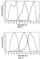
- Figure 1 compares the integral and analytical spectral sensitivity derived by the use of either form of densitometry in the course of the measurement of the speed points of image dye records formed from each of the red, green and blue sensitive units for a conventional color negative film intended for optical printing.
- the two forms densitometry give equivalent results.
- the degree of overlaps of sensitivity of the red, green and blue recording emulsion units apparently can lead to problems in accurately portraying the unit responsivity from integral densitometry.
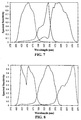
- Figure 2 shows that with a preferred embodiment of the invention, the off-peak absorptions of the same imperfect image dyes used in Sample 101 lead to increased off-peak color recording unit response when measured with integral densitometry, which vanishes when analytical densitometry is calculated to determine spectral response. It is preferred to calculate the spectral response of the color photographic elements of the invention using analytical densities. With alternate conventional cyan, magenta, and yellow image dyes showing reduced off-peak absorptance, or by the judicious selection of speed points that require larger unit responses that dominate the off-peak contributions, integral densities may be safely used to determine the color recording unit responsivity.
- Status M or Status A filter sets may have no distinct meaning. For example, if three differentiable infrared image dye-forming couplers with used with the red, green, and blue color recording units, then Status M densitometry of the imagewise exposed and developed photographic film may not reveal the formation of any dye images and incorrectly indicate no visible spectral response by the element. With such radical departures in image dye selections, then analytical densities, or reference printing densities or channel independent image-bearing electronic signals derived from scanning can be used to accurately gauge the spectral response of the photographic element.
- the wavelength of maximum sensitivity of the red recording emulsion layer unit falls between 580 and 620 nm. In preferred embodiments, the red maximum sensitivity falls between 580 and 610 nm. In more preferred forms the maximum sensitivity falls between 580 and 605 nm and in most preferred forms, the red maximum sensitivity is below 600 nm.
- the wavelength of maximum sensitivity of the green recording emulsion layer unit falls between 520 and 565 nm. In preferred embodiments, the green maximum sensitivity falls between 520 and 550 nm. Increased green recording unit bandwidth and short green sensitivity are essential features of the invention. Thus the normalized or relative sensitivity of the green recording unit at 50% of the maximum sensitivity spans at least 65 nm.
- this half peak bandwidth extends over at least 70 nm.
- the improved color accuracy of elements of the invention is attributable to high hypsochromic or short green sensitivity.
- the relative sensitivity of the green recording unit at 520 nm at least 60% of the maximum sensitivity exhibited by the unit, and more preferably it is at least 70%.
- red recording emulsion layer unit relative response at 560 nm exceeds 10% of the maximum unit sensitivity, and more preferably it exceeds 20%.
- Such high hypsochromic red recording unit sensitivity and high breadth of red response bridges the region of the spectrum between green and red and produces substantial overlap in the responses of the green and red emulsion layer units.
- the relative sensitivities of the red and green recording layer units overlap between 550 and 600 nm. More preferably, overlap occurs over the region spanning 565 to 590 nm.
- the overlap should exceed at least 35% of the maximum relative sensitivity of the normalized red and green recording layer units spectral response.
- the point of overlap where the spectral sensitivities are equal exceeds at least 45% of the maximum relative sensitivity. Overlap points exceeding 55% are contemplated to minimize metameric color capture failure completely.
- Image noise can be reduced, where the images are obtained by scanning exposed and processed color negative film elements to obtain a manipulatable electronic record of the image pattern, followed by reconversion of the adjusted electronic record to a viewable form.
- Image sharpness and colorfulness can be increased by designing layer gamma ratios to be within a narrow range while avoiding or minimizing other performance deficiencies, where the color record is placed in an electronic form prior to recreating a color image to be viewed.
- the red, green, and blue light sensitive color forming units each exhibit gamma ratios of less than 1.15. In an even more preferred embodiment, the red and blue light sensitive color forming units each exhibit gamma ratios of less than 1.10. In a most preferred embodiment, the red, green, and blue light sensitive color forming units each exhibit gamma ratios of less than 1.10. In all cases, it is preferred that the individual color unit(s) exhibit gamma ratios of less than 1.15, more preferred that they exhibit gamma ratios of less than 1.10 and even more preferred that they exhibit gamma ratios of less than 1.05. The gamma ratios of the layer units need not be equal.
- the color purity of the layer units should be maintained. Practically, this is achieved when the gamma ratios of the red, green, and blue color units are each greater than 0.80, preferably greater than 0.85, more preferably greater than 0.90, and most preferably greater than 0.95 so as to provide for adequate color separation during the overall image forming process.
- the minimum gamma ratio can be adjusted by selection of image couplers to be employed such that the unwanted absorptions of the dyes formed from such couplers during a development process are minimized. Many of the dye forming couplers originally employed in color photography are incapable of achieving this level of gamma ratio since their dye absorptances are excessively broad.
- Non-imagewise formation of dyes during the development process should also be limited or eliminated as, for example, by inclusion of interlayers having adequate quantities of oxidized developer scavengers and by the minimization of solution physical development. Further, adequate removal of non-imagewise densities as from retained silver or dyes from the element during processing enhances the color purity of the layer units.
- the gamma ratios described are realized by limiting or excluding colored masking couplers from the elements of the invention intended for color negative development. They are also realized by proper selection of DIR compounds. It is recognized that the gamma ratios may also be attained in other ways. In one concrete example, judicious choice and balancing of light sensitive emulsion halide content, may be employed to minimize the gamma ratio by minimizing the interaction of individual color records during development. Emulsion iodide content may be particularly critical in this role. Selection of the quantity of emulsion to be employed in each light sensitive layer and the sensitization conditions employed may also be critical.
- barrier layers which retard the flow of development inhibitors or of development by-products, such as halide ion, between layers so as to chemically isolate individual color recording units during development may also enable one to achieve this condition.
- fine grained non-light sensitive silver halide or silver particles may be employed to isolate color recording layers.
- polymer containing layers including those described by Pearce et al in U.S. Patent 5,254,441, the disclosures of which are incorporated by reference, may also be employed to isolate color recording layers.
- couplers and addenda which decrease chemical interactions between color layers may be advantageously employed. These materials include the ballasted mercaptotetrazole and derivative releasing couplers such as are described by Singer et al in U.S. Patent Application Serial No. 09/015,197 filed January 29, 1998, the disclosure of which is incorporated by reference.
- Elements having excellent light sensitivity are best employed in the practice of this invention.
- the elements should have a sensitivity of at least ISO 50, preferably have a sensitivity of at least ISO 100, and more preferably have a sensitivity of at least ISO 200. Elements having a sensitivity of up to ISO 3200 or even higher are specifically contemplated.
- the speed, or sensitivity, of a color negative photographic element is inversely related to the exposure required to enable the attainment of a specified density above fog after processing.
- Photographic speed for a color negative element with a gamma of 0.65 in each color record has been specifically defined by the American National Standards Institute (ANSI) as ANSI Standard Number PH 2.27-1981 (ISO (ASA Speed)) and relates specifically the average of exposure levels required to produce a density of 0.15 above the minimum density in each of the green light sensitive and least sensitive color recording unit of a color film.
- This definition conforms to the International Standards Organization (ISO) film speed rating.
- ISO International Standards Organization
- the ASA or ISO speed is to be calculated by linearly amplifying or deamplifying the gamma vs. log E (exposure) curve to a value of 0.65 before determining the speed in the otherwise defined manner.
- Silver iodobromide tabular grain emulsions EC-01, EC-02, EC-03, EC-04, and EC-05 were provided having the significant grain characteristics set out in Table 1-1 below. Tabular grains accounted for greater than 70 percent of total grain projected area in all instances.
- Each of Emulsions EC-01 through EC-05 were optimally sulfur and gold sensitized.
- these emulsions were optimally spectrally sensitized with SD-08, SD-07, SD-09, SD-10, and SD-11 in a 40 : 31 : 18 : 7 : 4 molar ratio.
- Emulsion size and iodide content Emulsion Average grain ECD ( ⁇ m) Average grain thickness, ( ⁇ m) Average Aspect Ratio Average Iodide Content (mol %) EC-01 2.20 0.12 18.3 3.9 EC-02 1.30 0.10 13.0 3.7 EC-03 0.90 0.12 7.5 3.7 EC-04 0.52 0.12 4.3 3.7 EC-05 0.57 0.07 8.1 1.3
- Silver iodobromide tabular grain emulsions EM-01, EM-02, EM-03, and EM-04 were provided having the significant grain characteristics set out in 1-2 below. Tabular grains accounted for greater than 70 percent of total grain projected area in all instances.
- Each of Emulsions EM-01 through EM-04 were optimally sulfur and gold sensitized.
- emulsions EM-01 and EM-02 were optimally spectrally sensitized with SD-04, SD-05, SD-06, and SD-07 in a 39.4 : 39.4 : 13.4: 7.8 molar ratio.
- Emulsions EM-03 and EM-04 were optimally spectrally sensitized with SD-04, SD-05, SD-06, and SD-07 in a 32.5 : 32.5 : 20 : 15 molar ratio.
- the wavelength of peak light absorption for all emulsions was around 540 nm, and the half-peak absorption bandwidth was around 75 nm.
- Substantial absorption was provided at 520, 550, and 560 nm.
- Emulsion size and iodide content Emulsion Average grain ECD ( ⁇ m) Average grain thickness, ( ⁇ m) Average Aspect Ratio Average Iodide Content (mol %) EM-01 1.50 0.29 5.2 3.6 EM-02 1.60 0.24 6.7 3.6 EM-03 0.90 0.12 7.5 3.7 EM-04 0.57 0.07 8.1 1.3
- Silver iodobromide tabular grain emulsions EY-01, EY-02, EY-03, EY-04, and EY-05 were provided having the significant grain characteristics set out in Table 1-3 below. Tabular grains accounted for greater than 70 percent of total grain projected area in all instances.
- Each of Emulsions EY-01 through EY-05 were optimally sulfur and gold sensitized.
- these emulsions were optimally spectrally sensitized with SD-01, SD-02, and SD-03 in a 49 : 31 : 20 molar ratio.
- the wavelength of peak light absorption for all emulsions was around 456 nm, and the half-peak dye absorption bandwidth was around 50 nm.
- Emulsion size and iodide content Emulsion Average grain ECD ( ⁇ m) Average grain thickness, ( ⁇ m) Average Aspect Ratio Average Iodide Content (mol %) EY-01 4.10 0.13 31.5 3.7 EY-02 2.20 0.12 18.3 3.9 EY-03 1.30 0.10 13.0 3.7 EY-04 0.52 0.12 4.3 3.7 EY-05 0.57 0.07 8.1 1.3
- Silver iodobromide tabular grain emulsions EC-06, EC-07, EC-08, and EC-09 were provided having the significant grain characteristics set out in Table 1-4 below. Tabular grains accounted for greater than 70 percent of total grain projected area in all instances.
- Each of Emulsions EC-06 through EC-09 were optimally sulfur and gold sensitized.
- these emulsions were optimally spectrally sensitized with SD-09 and SD-10 in a 2:1 molar ratio. The wavelength of peak light absorption for all emulsions was around 628 nm, and the half-peak absorption bandwidth was around 44 nm.
- Emulsion size and iodide content Emulsion Average grain ECD ( ⁇ m) Average grain thickness, ( ⁇ m) Average Aspect Ratio Average Iodide Content (mol %) EC-06 2.60 0.12 21.7 3.7 EC-07 1.30 0.12 10.8 4.1 EC-08 0.55 0.08 6.9 1.5 EC-09 0.66 0.12 5.5 4.1
- Silver iodobromide tabular grain emulsions EM-05, EM-06, EM-07, and EM-08 were provided having the significant grain characteristics set out in Table 1-5 below. Tabular grains accounted for greater than 70 percent of total grain projected area in all instances.
- Each of Emulsions EM-05 through EM-08 were optimally sulfur and gold sensitized.
- emulsions EM-05 through EM-08 were optimally spectrally sensitized with SD-05 and SD-12 in a four and a half to one molar ratio of dye. The wavelength of peak light absorption for all emulsions was around 545nm, and the half-peak dyed absorption bandwidth was around 48 run for all emulsions.
- Emulsion size and iodide content Emulsion Average grain ECD ( ⁇ m) Average grain thickness, ( ⁇ m) Average Aspect Ratio Average Iodide Content (mol %) EM-05 2.50 0.14 17.9 4.1 EM-06 1.20 0.11 10.9 4.1 EM-07 0.92 0.12 7.7 4.1 EM-08 0.81 0.12 6.8 2.6
- Emulsion EY-06 Silver iodobromide tabular grain emulsions EY-06, EY-07, EY-08, and EY-09 were provided having the significant grain characteristics set out in Table 1-6 below. Tabular grains accounted for greater than 70 percent of total grain projected area in all instances.
- Emulsion EY-06 a thick conventional grain was also provided.
- Each of Emulsions EY-06 through EY-09 were optimally sulfur and gold sensitized.
- these emulsions were optimally spectrally sensitized with SD-01 and SD-02 in a one to one molar ratio. The wavelength of peak light dye absorption for all emulsions was around 462 nm, and a second peak was present at around 442 nm.
- Emulsion size and iodide content Emulsion Average grain ECD ( ⁇ m) Average grain thickness, ( ⁇ m) Average Aspect Ratio Average Iodide Content (mol %) EY-06 1.04 Not applicable Not applicable 9.0 EY-07 1.30 0.14 9.3 4.1 EY-08 0.77 0.14 5.5 1.5 EY-09 0.55 0.08 6.9 1.5
- Silver iodobromide tabular grain unsensitized emulsions EC-10, EC-11, EC-12, EC-13, and EC-14 were identical to the unsensitized EC-01, EC-02, EC-03, EC-04, and EC-05, respectively.
- Each of emulsions EC-10 through EC-14 were optimally sulfur and gold sensitized.
- these emulsions were optimally spectrally sensitized with SD-05, SD-08, SD-07, SD-09, SD-10, and SD-11 in a 10 : 55 : 15 : 8 : 8 : 4 molar ratio.
- the wavelength of peak light absorption for all emulsions was around 567 nm, and the half-peak absorption bandwidth was around 70 nm.
- Silver iodobromide tabular grain emulsions unsensitized EC-15, EC-16, EC-17, EC-18, and EC-19 were identical to the unsensitized EC-01, EC-02, EC-03, EC-04, and EC-05, respectively.
- Each of emulsions EC-15 through EC-19 were optimally sulfur and gold sensitized.
- these emulsions were optimally spectrally sensitized with SD-17, SD-18, and SD-11 in a 55 : 35 : 10 molar ratio.
- the wavelength of peak light absorption for all emulsions was around 578, with a second peak at 610nm.
- the half-peak absorption bandwidth was over 59 nm.
- Silver iodobromide tabular grain unsensitized emulsions EC-20, EC-21, EC-22, EC-23, and EC-24 were identical to the unsensitized EC-01, EC-02, EC-03, EC-04, and EC-05, respectively.
- Each of emulsions EC-20 through EC-24 were optimally sulfur and gold sensitized.
- these emulsions were optimally spectrally sensitized with SD-10 and SD-19 in a 9 : 1 molar ratio.
- the wavelength of peak light absorption for all emulsions was around 653 nm, and the half-peak absorption bandwidth was around 36 nm.
- Silver iodobromide tabular grain emulsions EM-09, EM-10, EM-11, and EM-12 were provided having the significant grain characteristics set out in Table 1-7 below. Tabular grains accounted for greater than 70 percent of total grain projected area in all instances.
- Each of Emulsions EM-09 through EM-12 were optimally sulfur and gold sensitized.
- the emulsions were optimally spectrally sensitized with SD-13, SD-05, SD-06, and SD-07 in a 15 : 50 : 20 : 15 molar ratio.
- the wavelength of peak light absorption for all emulsions was around 558 nm, and the half-peak absorption bandwidth was around 73 nm.
- Emulsion size and iodide content Emulsion Average grain ECD ( ⁇ m) Average grain thickness, ( ⁇ m) Average Aspect Ratio Average Iodide Content (mol %) EM-09 2.40 0.12 20.0 3.6 EM-10 1.30 0.10 13.0 3.7 EM-11 0.90 0.12 7.5 3.7 EM-11 0.57 0.07 8.1 1.3
- Silver iodobromide tabular grain emulsions EM-13, EM-14, EM-15, and EM-16 were provided having the significant grain characteristics set out in Table 1-8 below. Tabular grains accounted for greater than 70 percent of total grain projected area in all instances.
- emulsions EM-13 through EM-16 were optimally sulfur and gold sensitized.
- the emulsions EM-13 and EM-14 were optimally spectrally sensitized with SD-14, SD-05, and SD-15 in a 23.6 : 38.2 : 38.2 molar ratio.
- Emulsions EM-15 and EM-16 were optimally spectrally sensitized with SD-14, SD-05, and SD-16 in a 23.6 : 38.2 : 38.2 molar ratio. The wavelength of peak light absorption for all emulsions was around 542 nm, and the half-peak absorption bandwidth was around 25 nm.
- Emulsion size and iodide content Emulsion Average grain ECD ( ⁇ m) Average grain thickness, ( ⁇ m) Average Aspect Ratio Average Iodide Content (mol %) EM-13 1.40 0.30 4.7 3.5 EM-14 0.70 0.34 2.1 3.5 EM-15 0.90 0.12 7.5 3.7 EM-16 0.57 0.07 8.1 1.3
- Silver iodobromide tabular grain emulsions EY-10, EY-11, EY-12, and EY-13 were provided having the significant grain characteristics set out in Table 1-9 below. Tabular grains accounted for greater than 70 percent of total grain projected area in all instances.
- Each of Emulsions EY-10 through EY-13 were optimally sulfur and gold sensitized.
- these emulsions were optimally spectrally sensitized with SD-01 and SD-02 in a 1 : 1 molar ratio.
- the wavelength of peak light dye absorption for all emulsions was around 462 nm, and a second peak was present at around 442 nm.
- the half-peak dyed absorption bandwidth was around 45 nm for all emulsions.
- Emulsion size and iodide content Emulsion Average grain ECD ( ⁇ m) Average grain thickness, ( ⁇ m) Average Aspect Ratio Average Iodide Content (mol %) EY-10 2.2 0.12 18.3 3.9 EY-11 1.30 0.10 13.0 3.7 EY-12 0.52 0.12 4.3 3.7 EY-13 0.57 0.07 8.1 1.3
- the slower, mid-speed, and faster emulsion layers within each of the blue (BU), green (GU), and red (RU) recording layer units are indicated by the prefix S, M, and F, respectively.
- This sample was prepared by applying the following layers in the sequence recited to a transparent film support of cellulose triacetate with conventional subbing layers, with the red recording layer unit coated nearest the support.
- the side of the support to be coated had been prepared by the application of gelatin subbing.
- Layer 1 AHU Black colloidal silver sol (0.151) UV-1 (0.075) UV-2 (0.108) Oxidized developer scavenger S-1 (0.161) Compensatory printing density cyan dye CD-1 (0.016) Compensatory printing density magenta dye MD-1 (0.038) Compensatory printing density yellow dye MM-2 (0.178) HBS-1 (0.105) HBS-2 (0.341) HBS-4 (0.038) HBS-7 (0.011) Disodium salt of 3,5-disulfocatechol (0.228) Gelatin (2.044)
- Layer 2 SRU This layer was comprised of a blend of a lower, medium, and higher (lower, medium, and higher grain ECD) sensitivity, red-sensitized tabular silver iodobromide emulsions.
- Emulsion EC-03 silver content (0.430) Emulsion EC-04, silver content (0.215) Emulsion EC-05, silver content (0.269) Bleach accelerator releasing coupler B-1 (0.057) Oxidized developer scavenger S-3 (0.183) Development inhibitor releasing coupler D-7 (0.013) Cyan dye forming coupler C-1 (0.344) Cyan dye forming coupler C-2 (0.038) HBS-2 (0.026) HBS-5 (0.118) HBS-6 (0.120) TAI (0.015) Gelatin (1.679) Layer 3: MRU Emulsion EC-02, silver content (1.076) Bleach accelerator releasing coupler B-1 (0.022) Development inhibitor releasing coupler D-1 (0.011) Development inhibitor releasing coupler D-7 (0.013) Oxidized developer scavenger S-3 (0.183) Cyan dye forming coupler C-1 (0.086) Cyan dye forming coupler C-2 (0.086) HBS-1 (0.044) HBS-2 (0.026) HBS-5
- Emulsion EY-02 silver content (0.323) Emulsion EY-03, silver content (0.247) Emulsion EY-04, silver content (0.215) Emulsion EY-05, silver content (0.269) Bleach accelerator releasing coupler B-1 (0.003) Development inhibitor releasing coupler D-7 (0.011) Oxidized developer scavenger S-3 (0.183) Yellow dye forming coupler Y-1 (0.710) HBS-2 (0.022) HBS-5 (0.151) HBS-6 (0.050) TAI (0.016) Gelatin (1.872)
- Layer 11 FBU Emulsion EY-01, silver content (0.699) Bleach accelerator releasing coupler B-1 (0.005) Development inhibitor releasing coupler D-7 (0.013) Yellow dye forming coupler Y-1 (0.140) HBS-2 (0.026) HBS-5 (0.118) HBS-6 (0.007) TAI (0.011) Gelatin (1.291)
- Layer 12 Protective Overcoat Layer Polymethylmethacrylate matte beads (0.005) Soluble polymethylmeth
- This film was hardened at the time of coating with 1.75% by weight of total gelatin of hardener H-1.
- Surfactants, coating aids, soluble absorber dyes, antifoggants, stabilizers, antistatic agents, biostats, biocides, and other addenda chemicals were added to the various layers of this sample, as is commonly practiced in the art.
- This sample was prepared by applying the following layers in the sequence recited to a transparent film support of cellulose triacetate with conventional subbing layers, with the red recording layer unit coated nearest the support.
- the side of the support to be coated had been prepared by the application of gelatin subbing.
- Layer 1 AHU Black colloidal silver sol (0.107) UV-1 (0.075) UV-2 (0.075) Oxidized developer scavenger S-1 (0.161) Compensatory printing density cyan dye CD-1 (0.034) Compensatory printing density magenta dye MD-1 (0.013) Compensatory printing density yellow dye MM-2 (0.095) HBS-1 (0.105) HBS-2 (0.433) HBS-4 (0.013) Disodium salt of 3,5-disulfocatechol (0.215) Gelatin (2.152)
- Layer 2 SRU This layer was comprised of a blend of a lower and higher (lower and higher grain ECD) sensitivity, red-sensitized tabular silver iodobromide emulsions respectively.
- Layer 3 MRU Emulsion EC-07, silver content (1.162) Bleach accelerator releasing coupler B-1 (0.005) Development inhibitor releasing coupler D-5 (0.016) Cyan dye forming magenta colored coupler CM-1 (0.059) Cyan dye forming coupler C-1 (0.207) HBS-2 (0.253) HBS-6 (0.007) TAI (0.019) Gelatin (1.291)
- Layer 4 FRU Emulsion EC-06, silver content (1.060) Bleach accelerator releasing coupler B-1 (0.005) Development inhibitor releasing coupler D-5 (0.027) Development inhibitor releasing coupler D-1 (0.048) Cyan dye forming magenta
- Layer 7 MGU This layer was comprised of a blend of a lower and higher (lower and higher grain ECD) sensitivity, green-sensitized tabular silver iodobromide emulsions.
- Layer 8 FGU Emulsion EM-05, silver content (0.909) Development inhibitor releasing coupler D-3 (0.003) Development inhibitor releasing coupler D-7 (0.032) Oxidized developer scavenger S-2 (0.023) Magenta dye forming yellow colored coupler MM-1 (0.054) Magenta dye forming coupler M-1 (0.113) HBS-1 (0.216) HBS-2 (0.064) Stabilizer ST-1 (0.011) TAI (0.011) Gelatin (1.405)
- Layer 9 Yellow Filter Layer Yellow filter
- Emulsion EY-06 silver content (0.699) Unsensitized silver bromide Lippmann emulsion (0.054) Yellow dye forming coupler Y-1 (0.473) Development inhibitor releasing coupler D-4 (0.086) Bleach accelerator releasing coupler B-1 (0.005) HBS-1 (0.280) HBS-6 (0.007) TAI (0.012) Gelatin (1.183)
- Layer 12 Ultraviolet Filter Layer Dye UV-1 (0.108) Dye UV-2 (0.108) Unsensitized silver bromide Lippmann emulsion (0.215) HBS-1 (0.151) Gelatin (0.699)
- Layer 13 Protective Overcoat Layer Polymethylmethacrylate matte beads (0.005) Soluble polymethylmethacrylate matte beads (0.108) Silicone lubricant (0.039) Gelatin (0.882)
- This film was hardened at the time of coating wit 1.80% by weight of total gelatin of hardener H-1.
- Surfactants, coating aids, soluble absorber dyes, antifoggants, stabilizers, antistatic agents, biostats, biocides, and other addenda chemicals were added to the various layers of this sample, as is commonly practiced in the art.
- Sample 103 (Invention) color photographic recording material for color negative development was prepared exactly as above in Sample 101, except where noted below.
- Layer 10 SBU Changes Emulsion EY-05, silver content (0.000) Emulsion EY-04, silver content (0.000) Emulsion EY-03, silver content (0.000) Emulsion EY-02, silver content (0.000) Emulsion EY-13, silver content (0.269) Emulsion EY-12, silver content (0.215) Emulsion EY-11, silver content (0.247) Emulsion EY-10, silver content (0.323)
- Layer 11 FB U Changes Emulsion EY-01 (0.000) Emulsion EY-06 (0.699)
- Sample 104 (Invention) color photographic recording material for color negative development was prepared exactly as above in Sample 101, except where noted below.
- Layer 2 SRU Changes Emulsion EC-03, silver content (0.000) Emulsion EC-04, silver content (0.000) Emulsion EC-05, silver content (0.000) Emulsion EC-12, silver content (0.430) Emulsion EC-13, silver content (0.215) Emulsion EC-14, silver content (0.269)
- Layer 3 MRU Changes Emulsion EC-02, silver content (0.000) Emulsion EC-11, silver content (1.076)
- Layer 4 FRU Changes Emulsion EC-01, silver content (0.000) Emulsion EC-10, silver content (01.291)
- Layer 6 SGU Changes Emulsion EM-03, silver content (0.000) Emulsion EM-04, silver content (0.000) Emulsion EM-11, silver content (0.323) Emulsion EM-12, silver content (0.215)
- Layer 7 MGU Changes Emulsion EM-
- Sample 105 (Comparative control) color photographic recording material for color negative development was prepared exactly as above in Sample 103, except where noted below.
- Layer 2 SRU Changes Emulsion EC-03, silver content (0.000) Emulsion EC-04, silver content (0.000) Emulsion EC-05, silver content (0.000) Emulsion EC-17, silver content (0.430) Emulsion EC-18, silver content (0.215) Emulsion EC-19, silver content (0.269)
- Layer 3 MRU Changes Emulsion EC-02, silver content (0.000) Emulsion EC-16, silver content (1.076)
- Layer 4 FRU Changes Emulsion EC-01, silver content (0.000) Emulsion EC-15, silver content (1.291)
- Layer 6 SGU Changes Emulsion EM-03, silver content (0.000) Emulsion EM-04, silver content (0.000) Emulsion EM-15, silver content (0.323) Emulsion EM-16, silver content (0.215)
- Layer 7 MGU Changes Emulsion
- Sample 106 (Comparative control) color photographic recording material for color negative development was prepared exactly as above in Sample 101, except where noted below.
- Layer 6 SGU Changes Emulsion EM-03, silver content (0.000) Emulsion EM-04, silver content (0.000) Emulsion EM-15, silver content (0.323) Emulsion EM-16, silver content (0.215)
- Layer 7 MGU Changes Emulsion EM-02, silver content (0.000) Emulsion EM-14, silver content (0.968)
- Layer 8 FGU Changes Emulsion EM-01, silver content (0.000) Emulsion EM-13, silver content (0.968)
- Sample 107 (Comparative control) color photographic recording material for color negative development was prepared exactly as above in Sample 101, except where noted below.
- Layer 2 SRU Changes Emulsion EC-03, silver content (0.000) Emulsion EC-04, silver content (0.000) Emulsion EC-05, silver content (0.000) Emulsion EC-22, silver content (0.430) Emulsion EC-23, silver content (0.215) Emulsion EC-24, silver content (0.269)
- Layer 3 MRU Changes Emulsion EC-02, silver content (0.000) Emulsion EC-21, silver content (1.076)
- Layer 4 FRU Changes Emulsion EC-01, silver content (0.000) Emulsion EC-20, silver content (1.291)
- Samples 101 ⁇ 107 were subjected to Status M densitometry and their sensitometric performance over the visible spectrum was characterized.
- the exposure required to produce a density increase of 0.20 above Dmin was determined for the color recording units at each 5-nm increment exposed.
- the exposure distribution for each of the red, green and blue responsivities was normalized by its maximum sensitivity to convert each of the 5-nm sample sensitivities to relative sensitivities for plotting as a function of wavelength, as in Fig. 1 and 2.
- a second set of speeds was generated by taking the Status M densitometry and transforming it to analytical densities using a 3x3 matrix treatment appropriate for the image dye set according to methods disclosed in the art cited earlier. .
- the exposure required to produce a analytical density increase of 0.20 above Dmin was determined for the color recording units at each 5-nm increment exposed.
- the exposure distribution for each of the red, green and blue responsivities was normalized by its maximum sensitivity to convert each of the 5-nm sample sensitivities to relative sensitivities for plotting, as also in Fig. 1 and 2, and Fig. 3 to 9 as well.
- the spectral sensitivity response of the photographic recording materials was also used to determine the relative colorimetric accuracy of color negative materials Samples 101 ⁇ 107 in recording a particular diverse set of 200 different color patches according to the method disclosed by Giorgianni et al, in U.S. Patent 5,582,961.
- the computed color error variance is included in Table 3-1. This error value relates to the color difference between the CIELAB space coordinates of the specified set of test colors and the space coordinates resulting from a specific transformation of the test colors as rendered by the film.
- the test patch input spectral reflectance values for a given light source are convolved with the sample photographic materials' spectral sensitivity response to estimate colorimetric recording capability.
- the computed color error is sensitive to the responses of all three input color records, and an improved response by one record may not overcome the responses of one or two other limiting color records.
- a color error difference of at least 1 unit corresponds to a significant difference in color recording accuracy.
- the points divergence of the comparative controls from the requirements of the invention are highlighted in bold.
Landscapes
- Physics & Mathematics (AREA)
- General Physics & Mathematics (AREA)
- Silver Salt Photography Or Processing Solution Therefor (AREA)
Abstract
A color photographic element particularly useful for
colorimetrically accurate recording of scene exposures is disclosed, which is
capable of producing differentiable dye images suitable for scanning and
electronic image processing. The element has red, green and blue light recording
silver halide emulsion layer units and provides broad, hypsochromic green
spectral sensitivity that overlaps with the red spectral sensitivity. The wavelength
of maximum sensitivity of the red recording emulsion layer unit is between about
580 and 620 nm, the wavelength of maximum sensitivity of the green recording
emulsion layer unit is between about 520 and 565 nm, the relative sensitivity of
the green recording emulsion layer unit at 50% of the maximum sensitivity
exhibits an overall breadth of at least about 65 nm, and the relative sensitivity of
the green recording emulsion layer unit at 520 nm is at least 60% of the
maximum.
Description
- The field of the invention is color photographic films intended to be scanned in order to retrieve the recorded image for viewing. The element is particularly suitable for accurately capturing scene light exposures with high colorimetric precision, where image transformation to a viewable form is achieved by film scanning, electronic signal processing, and image file transfer to an output device.
- In referring to grains and emulsions containing two or more halides, the halides are named in order of ascending concentrations.
- The terms "high chloride" and "high bromide" in referring to grains and emulsions indicate that chloride or bromide, respectively, is present in a concentration of greater than 50 mole percent, based on silver.
- The term "equivalent circular diameter" or "ECD" is employed to indicate the diameter of a circle having the same projected area as a silver halide grain.
- The term "aspect ratio" designates the ratio of grain ECD to grain thickness (t).
- The term "tabular grain" indicates a grain having two parallel crystal faces which are clearly larger than any remaining crystal faces and an aspect ratio of at least 2.
- The term "tabular grain emulsion" refers to an emulsion in which tabular grains account for greater than 50 percent of total grain projected area.
- The terms "blue spectral sensitizing dye", "green spectral sensitizing dye", and "red spectral sensitizing dye" refer to a dye or combination of dyes that sensitize silver halide grains and, when adsorbed, have their peak absorption in the blue, green and red regions of the spectrum, respectively.
- The term "half-peak bandwidth" in referring to a dye indicates the spectral region over which absorption exhibited by the dye is at least half its absorption at its wavelength of maximum absorption.
- In referring to blue, green and red recording dye image forming layer units, the term "layer unit" indicates the layer or layers that contain radiation-sensitive silver halide grains to capture exposing radiation and that contain couplers that react upon development of the grains. The grains and couplers are usually in the same layer, but can be in adjacent layers.
- The term "overall half-peak bandwidth" indicates the spectral region over which a combination of spectral sensitizing dyes within a layer unit exhibits absorption that is at least half their combined maximum absorption at any single wavelength.
- The term "dye image-forming coupler" indicates a coupler that reacts with oxidized color developing agent to produce a dye image.
- The term "colored masking coupler" indicates a coupler that is initially colored and that loses its initial color during development upon reaction with oxidized color developing agent.
- The term "substantially free of colored masking coupler" indicates a total coating coverage of less than 0.02 millimole/m2 of colored masking coupler.
- The term "development inhibitor releasing compound" or "DIR" indicates a compound that cleaves to release a development inhibitor during color development. As defined DIR's include couplers and other compounds that utilize anchimeric and timed releasing mechanisms.
- The term "Status M" density indicates density measurements obtained from a densitometer meeting photocell and filter specifications described in SPSE Handbook of Photographic Science and Engineering, W. Thomas, editor, John Wiley & Sons, New York, 1973, Section 15.4.2.6 Color Filters. The International Standard for Status M density is set out in "Photography--Density Measurements--Part 3: Spectral conditions", Ref. No. ISO 5/3-1984 (E).
- The term "exposure latitude" indicates the exposure range of a characteristic curve segment over which instantaneous gamma (ΔD/Δlog E) is at least 25 percent of gamma, as defined above. The exposure latitude of a color element having multiple color recording units is the exposure range over which the characteristic curves of the red, green, and blue color recording units simultaneously fulfill the aforesaid definition.
- The term "gamma ratio" when applied to a color recording layer unit refers to the ratio determined by dividing the color gamma of a cited layer unit after an imagewise color separation exposure and process that enables development of primarily that layer unit by the color gamma of the same layer unit after an imagewise white light exposure and process that enables development of all layer units. This term relates to the degree of color saturation available from that layer unit after conventional optical printing. Larger values of the gamma ratio indicate enhanced degrees of color saturation under optical printing conditions.
- Research Disclosure is published by Kenneth Mason Publications, Ltd., Dudley House, 12 North St., Emsworth, Hampshire P010 7DQ, England.
- Photographic recording materials have historically been designed to operate in an analog world involving direct optical print-through to a reflection print material or direct viewing of transmitted light, depending on the mode of image development. Color negative films record scene light exposures and, following development and chemical image processing through interlayer interimage effects generally produced by colored masking couplers and development inhibitor releasing couplers, yield orange masked-films suitable for the attenuation of light to allow the exposure of silver halide color paper giving a viewable representation of the scene after its processing and drying. Color reversal films record scene light exposures and, following development and chemical image processing through interlayer interimage effects generally produced by first development iodide gradients and second development inhibitor releasing couplers, yield positive images suitable for projection and viewing in a dark surround. The accuracy of recording the different colors of visible light in the scene exposures is limited by either the constituents the films were required to contain to perform their function (e.g. colored masking couplers in color negative films) or the degree of chemical image processing achievable for color correction or 'management' by chemical development modification.
- With the introduction of color film scanning, however, the role of films in producing images is fundamentally changed. The color film image dye densities of films designed exclusively for scanning are no longer required to attenuate the precise exposure of silver halide color paper or the human eye with fully color corrected dye hues. A suitable exposure of scanner charged coupled device arrays to create image-bearing electronic signals can be accomplished with image dye amounts that have not been modified by development interlayer interimage effects. The color correction that was formally performed chemically can be done with higher effectiveness by mathematical transformations of the electronic signals which are required anyway to convert the image-bearing signals back into a viewable form, such as to code values used by a computer color monitor display or by a writing device such as an inkjet printer. In relying on electronic image processing, the color films can be re-designed to record scene exposures with greater accuracy. More accurate color recording of the scene light is in fact vital to obtain the full benefit of such hybrid systems. The unique non-linear signal amplifications available to electronic image processsing can produce a multitude of different high quality renditions of the scene, depending on individual preferences, but these renditions will be unfaithful in their color rendition and disappointing, if the color film failed to record the scene exposures correctly at the time of photography. Such color accuracy requirements are found in metameric color failure, where the certain objects with very different spectral reflectance properties stimulate the human visual system sensitivities the same. Since optical color film spectral sensitivities differ from that of the eye, theses films record the scene exposures differently leading to color recording errors. In certain artificial illuminants, such as inexpensive fluorescent lights, closely spaced line emissions by the tube phosphors correctly stimulate the overlapping eye RGB channels to produce the appearance of neutral white light, and nearly normal white light colors of viewed objects or subjects results. The non-overlapping spectral sensitivities of color films result in relatively large color recording gaps, and inaccurate color rendition the same objects or subjects inevitably results. Color films designed for scanning and electronic processing of the image-bearing signals can benefit from silver halide emulsion spectral sensitivity that is more colorimetrically accurate.
- Examples of spectral sensitivities that better approximate the human visual response and which resemble color matching functions have been described. MacAdam (Pearson and Yule, J. Color Appearance, 2, 30 (1973)), Schwan et al U.S. Patent 3,672,898 and Giorgianni et al U.S. Patent 5,609,978 and U.S. Patent 5,582,961 are illustrative of attempts to improve color reproduction by intentionally selecting spectral sensitizing dye combinations for blue, green, and red recording layer units that overlap more and differ from the wavelengths of maximum relative sensitivity of usual analog optical system color films. Giorgianni et al '978 and '961 are herein incorporated by reference. Schwan et al however stipulate that the cyan dye image-forming layer contain at least one light sensitive silver halide emulsion with a maximum sensitivity greater than 603 nm. In addition, the red recording unit is comprised of a magenta colored filter dye material which absorbs visible radiation shorter than the maximum sensitivity of said cyan-dye forming unit. Adequate red recording unit hypsochromic sensitivity for optimal colorimetrically accurate capture is not provided in the presence of the magenta trimmer dye filtering the scene exposures incident on it. Giorgianni et al demonstrate color reversal films with red recording unit maximum sensitivity around 600 nm, with broad half-peak bandwidth relative sensitivity in the same red unit, and with substantially overlapping green and red recording silver halide emulsion unit spectral sensitivity. But the green recording silver halide emulsion unit 50%-maximum peak bandwidth spans only 60 nm , and sensitivity at 520 nm in the hypsochromic, shorter green region is 53% of the maximum relative sensitivity. In addition, the blue recording silver halide unit maximum sensitivity is found at 422 nm, contributing to reduced blue and green recording unit overlapping sensitivity. In aggregate, the colorimetric accuracy of the element was handicapped by these flaws.
- In order to achieve accurate color reproduction, the photographic element red and green sensitivity must meet certain requirements provided by dyed silver halide emulsions. The green and red maximum sensitivities must fall somewhat more hypsochromic of their usual positions in films designed for direct optical printing or viewing. The green record sensitivity must be broad, with substantial relative short green responsivity. The need for high color accuracy recording by a silver halide emulsion-based image capture element that provides the colorimetry of scene exposures remains unsatisfied .
- The present invention can be viewed as an improvement on teachings of Buitano et al in that it has been discovered that improved color capture accuracy can be achieved when the green unit spectral relative spectral sensitivity at 520 nm is at least 60% of the maximum sensitivity.
- In one aspect this invention is directed to a color photographic element capable of producing dye images suitable for digital scanning comprised of:
- a support and, coated on the support,
- a plurality of hydrophilic colloid layers including a blue recording emulsion layer unit capable of forming a dye image of a first hue, a green recording emulsion layer unit capable of forming a dye image of a second hue, and a red recording emulsion layer unit capable of forming a dye image of a third hue, wherein,
- the wavelength of maximum sensitivity of the red recording emulsion layer unit is between 580 and 620 nm, the wavelength of maximum sensitivity of the green recording emulsion layer unit is between 520 and 565 nm, the relative sensitivity of the green recording emulsion layer unit at 50% of the maximum sensitivity exhibits an overall breadth of at least 65 nm, the relative sensitivity of the green recording emulsion layer unit at 520 nm is at least 60% of the maximum, with the proviso that magenta colored filter materials are absent from the red recording emulsion layer unit.
-
- When photographic recording materials according to the invention are prepared, shorter red spectral sensitivity, with maximum response of between 580 and 620 nm, and broad green spectral sensitivity, at a maximum sensitivity between 520 and 560 nm, is produced with significant relative sensitivity at wavelengths between 500 and 575 nm and specifically at shorter green light wavelengths around 520 nm. In preferred embodiments of the invention, the broad green sensitivity is produced in conjunction with a broad red spectral sensitivity which provides for significant overlap of the green and red responsivities at a significant fraction of the maximum relative sensitivity, in analogy with the human visual response. Elements in accord with the invention can achieve low color recording errors by accurately capturing scene light exposures which provides the opportunity for improved hybrid photographic-electronic imaging system color reproduction fidelity.
- Fig. 1 compares color photographic recording material relative spectral sensitivity responses derived from Status M densities (dash line) and analytical densities (solid line) for comparative control Sample 102 below of the conventional color negative film art.
- Fig. 2 compares color photographic recording material relative spectral sensitivity responses derived from Status M densities (dash line) and analytical densities (solid line) for inventive color negative film Sample 101 below.
- Fig. 3 shows color photographic recording material relative spectral sensitivity responses for color negative film Sample 101 below which are one preferred set of spectral sensitivities according to the present invention.
- Fig. 4 shows color photographic recording material relative spectral sensitivity responses for color negative film Sample 103 below which are a second preferred set of spectral sensitivities according to the present invention.
- Fig. 5 shows color photographic recording material relative spectral sensitivity responses for inventive color negative film Sample 104 below, which are a third preferred set of spectral sensitivities according to the present invention..
- Fig. 6 shows color photographic recording material relative spectral sensitivity responses for comparative control color negative film Sample 105 below which are a representative set of color matching function spectral sensitivities of the prior art.
- Fig. 7 shows color photographic recording material relative spectral sensitivity responses for comparative control color negative film Sample 106 below.
- Fig. 8 shows color photographic recording material relative spectral sensitivity responses for comparative control color negative film Sample 107 below.
- Fig. 9 shows color photographic recording material relative spectral sensitivity responses for comparative control color negative film. Sample 102 below.
-
- A typical color negative film construction useful in the practice of the invention is illustrated by the following:
Element SCN-1 SOC Surface Overcoat BU Blue Recording Layer Unit IL1 First Interlayer GU Green Recording Layer Unit IL2 Second Interlayer RU Red Recording Layer Unit AHU Antihalation Layer Unit S Support SOC Surface Overcoat - The support S can be either reflective or transparent, which is usually preferred. When reflective, the support is white and can take the form of any conventional support currently employed in color print elements. When the support is transparent, it can be colorless or tinted and can take the form of any conventional support currently employed in color negative elements―e.g., a colorless or tinted transparent film support. Details of support construction are well understood in the art. The element can contain additional layers, such as filter layers, interlayers, overcoat layers, subbing layers, or antihalation layers. Transparent and reflective support constructions, including subbing layers to enhance adhesion, are disclosed in Research Disclosure, Item 38957, cited above, XV. Supports. Photographic elements of the present invention may also usefully include a magnetic recording material as described in Research Disclosure, Item 34390, November 1992, or a transparent magnetic recording layer such as a layer containing magnetic particles on the underside of a transparent support as in US Patent No. 4,279,945, and US Pat. No. 4,302,523.
- Each of blue, green and red recording layer units BU, GU and RU are formed of one or more hydrophilic colloid layers and contain at least one radiation-sensitive silver halide emulsion and coupler, including at least one dye image-forming coupler. It is preferred that the green, and red recording units are subdivided into at least two recording layer sub-units to provide increased recording latitude and reduced image granularity. In the simplest contemplated construction each of the layer units or layer sub-units consists of a single hydrophilic colloid layer containing emulsion and coupler. When coupler present in a layer unit or layer sub-unit is coated in a hydrophilic colloid layer other than an emulsion containing layer, the coupler containing hydrophilic colloid layer is positioned to receive oxidized color developing agent from the emulsion during development. Usually the coupler containing layer is the next adjacent hydrophilic colloid layer to the emulsion containing layer.
- In order to ensure excellent image sharpness, and to facilitate manufacture and use in cameras, all of the sensitized layers are preferably positioned on a common face of the support. When in spool form, the element will be spooled such that when unspooled in a camera, exposing light strikes all of the sensitized layers before striking the face of the support carrying these layers. Further, to ensure excellent sharpness of images exposed onto the element, the total thickness of the layer units above the support should be controlled. Generally, the total thickness of the sensitized layers, interlayers and protective layers on the exposure face of the support are less than 35 µm. It is preferred that the total layer thickness be less than 28 µm, more preferred that the total layer thickness be less than 22 µm, and most preferred that the total layer thickness be less than 17 µm. This constraint on total layer thickness is enabled by controlling the total quantity light sensitive silver halide as described below, and by controlling the total quantity of vehicle and other components, such as couplers, solvent, and such in the layers. The total quantity of vehicle is generally less than 20 g/m2, preferably less than 14 g/m2, and more preferably less than 10 g/m2. Generally, at least 3 g/m2 of vehicle, and preferably at least 5 g/m2 of vehicle is present so as to ensure adhesion of the layers to the support during processing and proper isolation of the layer components. Likewise, the total quantity of other components is generally less than 12 g/m2, preferably less than 8 g/m2, and more preferably less than 5 g/m2.
- The emulsion in BU is capable of forming a latent image when exposed to blue light. When the emulsion contains high bromide silver halide grains and particularly when minor (0.5 to 20, preferably 1 to 10, mole percent, based on silver) amounts of iodide are also present in the radiation-sensitive grains, the native sensitivity of the grains can be relied upon for absorption of blue light. Preferably the emulsion is spectrally sensitized with two or more blue spectral sensitizing dyes to achieve the required absorption breadth of color matching function spectral sensitivity which mimics human visual sensitivity. Tabular emulsions are preferred for providing dyed blue spectral sensitivity. The emulsions in GU and RU are spectrally sensitized with green and red spectral sensitizing dyes, respectively, in all instances, since silver halide emulsions have no native sensitivity to green and/or red (minus blue) light. The red unit emulsions of the invention preferably are comprised of at least four spectral sensitizing dyes. More preferably, at least five spectral sensitizing dyes are employed to achieve the required spectral breadth of responsivity to green-red light.
- Any convenient selection from among conventional radiation-sensitive silver halide emulsions can be incorporated within the layer units and used to provide the spectral absorptances of the invention. Most commonly high bromide emulsions containing a minor amount of iodide are employed. To realize higher rates of processing, high chloride emulsions can be employed. Radiation-sensitive silver chloride, silver bromide, silver iodobromide, silver iodochloride, silver chlorobromide, silver bromochloride, silver iodochlorobromide and silver iodobromochloride grains are all contemplated. The grains can be either regular or irregular (e.g., tabular). Tabular grain emulsions, those in which tabular grains account for at least 50 (preferably at least 70 and optimally at least 90) percent of total grain projected area are particularly advantageous for increasing speed in relation to granularity. To be considered tabular a grain requires two major parallel faces with a ratio of its equivalent circular diameter (ECD) to its thickness of at least 2. Specifically preferred tabular grain emulsions are those having a tabular grain average aspect ratio of at least 5 and, optimally, greater than 8. Preferred mean tabular grain thicknesses are less than 0.3 µm (most preferably less than 0.2 µm). Ultrathin tabular grain emulsions, those with mean tabular grain thicknesses of less than 0.07 µm, are specifically preferred for the blue sensitive recording unit. The green sensitive recording unit is preferably comprised of tabular grains with an aspect ratio of less than or equal to 15. The grains preferably form surface latent images so that they produce negative images when processed in a surface developer in color negative film forms of the invention.
- Illustrations of conventional radiation-sensitive silver halide emulsions are provided by Research Disclosure, Item 38957, cited above, I. Emulsion grains and their preparation. Chemical sensitization of the emulsions, which can take any conventional form, is illustrated in section IV. Chemical sensitization. Spectral sensitization and sensitizing dyes, which can take any conventional form, are illustrated by section V. Spectral sensitization and desensitization. The emulsion layers also typically include one or more antifoggants or stabilizers, which can take any conventional form, as illustrated by section VII. Antifoggants and stabilizers.
- While any useful quantity of light sensitive silver, as silver halide, can be employed in the elements useful in this invention, it is preferred that the total quantity be less than 10 g/m2 of silver. Silver quantities of less than 7 g/m2 are preferred, and silver quantities of less than 5 g/m2 are even more preferred. The lower quantities of silver improve the optics of the elements, thus enabling the production of sharper pictures using the elements. These lower quantities of silver are additionally important in that they enable rapid development and desilvering of the elements. Conversely, a silver coating coverage of at least 2 g of coated silver per m2 of support surface area in the element is necessary to realize an exposure latitude of at least 2.7 log E while maintaining an adequately low graininess position for pictures intended to be enlarged. The green light recording layer unit is preferred to have a coated silver coverage of at least 0.8 g/m2. It is more preferred that the red and green units together have at least 1.7 g/m2 of coated silver and even more preferred that each of the red, green, and blue color units has at least 0.8 g/m2 of coated silver. Because of its less favored location for processing, it is generally preferred that the layer unit located, on average, closest to the support contain a silver coating coverage of at least 1.0 g/m2 of coated silver. Typically, this is the red recording layer unit. For many photographic applications, optimum silver coverages are at least 0.9 g/m2 in the blue recording layer unit and at least 1.5 g/m2 in the green and red recording layer units.
- BU contains at least one yellow dye image-forming coupler, GU contains at least one magenta dye image-forming coupler, and RU contains at least one cyan dye image-forming coupler. Any convenient combination of conventional dye image-forming couplers can be employed. Conventional dye image-forming couplers are illustrated by Research Disclosure , Item 38957, cited above, X. Dye image formers and modifiers, B. Image-dye-forming couplers. Magenta colored masking couplers are absent from RU.
- The invention is applicable to conventional color negative film or color reversal film constructions. The spectral sensitivities can also be employed in photothermographic elements, and in particular, camera speed photothermographic elements as known in the art. Specific examples of multicolor photothermographic elements are described by Levy et al. In United States Patent Application Serial Number 08/740,110, filed 28 October 1996, by Ishikawa et al in European
Patent Application EP 0, 762,201 A1, and by Asami in US Patent 5,573,560, the disclosures of which are both incorporated by reference. The invention is also applicable to image transfer photothermographic elements such as disclosed in Ishikawa et al EuropeanPatent Application EP 0 800 114 A2. In a preferred embodiment, contrary to conventional color negative film constructions, RU, GU and BU are each substantially free of colored masking coupler. Preferably the layer units each contain less than 0.02 (most preferably less than 0.01) millimole/m2 of colored masking coupler. No colored masking coupler is required in the color negative elements of this invention. - Development inhibitor releasing compound is incorporated in at least one and, preferably, each of the layer units in color negative film forms of the invention. DIR's are commonly employed to improve image sharpness and to tailor dye image characteristic curve shapes. The DIR's contemplated for incorporation in the color negative elements of the invention can release development inhibitor moieties directly or through intermediate linking or timing groups. The DIR's are contemplated to include those that employ anchimeric releasing mechanisms. Illustrations of development inhibitor releasing couplers and other compounds useful in the color negative elements of this invention are provided by Research Disclosure, Item 38957, cited above, X. Dye image formers and modifiers, C. Image dye modifiers, particularly paragraphs (4) to (11).
- It is common practice to coat one, two or three separate emulsion layers within a single dye image-forming layer unit. When two or more emulsion layers are coated in a single layer unit, they are typically chosen to differ in sensitivity. When a more sensitive emulsion is coated over a less sensitive emulsion, a higher speed is realized than when the two emulsions are blended. When a less sensitive emulsion is coated over a more sensitive emulsion, a higher contrast is realized than when the two emulsions are blended. It is preferred that the most sensitive emulsion be located nearest the source of exposing radiation and the slowest emulsion be located nearest the support.
- One or more of the layer units of the invention is preferably subdivided into at least two, and more preferably three or more sub-unit layers. It is preferred that all light sensitive silver halide emulsions in the color recording unit have spectral sensitivity in the same region of the visible spectrum. In this embodiment, while all silver halide emulsions incorporated in the unit have spectral absorptance according to invention, it is expected that there are minor differences in spectral absorptance properties between them. In still more preferred embodiments, the sensitizations of the slower silver halide emulsions are specifically tailored to account for the light shielding effects of the faster silver halide emulsions of the layer unit that reside above them, in order to provide an imagewise uniform spectral response by the photographic recording material as exposure varies with low to high light levels. Thus higher proportions of peak light absorbing spectral sensitizing dyes may be desirable in the slower emulsions of the subdivided layer unit to account for on-peak shielding and broadening of the underlying layer spectral sensitivity.
- The interlayers IL1 and IL2 are hydrophilic colloid layers having as their primary function color contamination reduction―i.e., prevention of oxidized developing agent from migrating to an adjacent recording layer unit before reacting with dye-forming coupler. The interlayers are in part effective simply by increasing the diffusion path length that oxidized developing agent must travel. To increase the effectiveness of the interlayers to intercept oxidized developing agent, it is conventional practice to incorporate oxidized developing agent. Antistain agents (oxidized developing agent scavengers) can be selected from among those disclosed by Research Disclosure, Item 38957, X. Dye image formers and modifiers, D. Hue modifiers/stabilization, paragraph (2). When one or more silver halide emulsions in GU and RU are high bromide emulsions and, hence have significant native sensitivity to blue light, it is preferred to incorporate a yellow filter, such as Carey Lea silver or a yellow processing solution decolorizable dye, in IL1. Suitable yellow filter dyes can be selected from among those illustrated by Research Disclosure, Item 38957, VIII. Absorbing and scattering materials, B. Absorbing materials. In elements of the instant invention, magenta colored filter materials we absent from IL2 and RU.
- The antihalation layer unit AHU typically contains a processing solution removable or decolorizable light absorbing material, such as one or a combination of pigments and dyes. Suitable materials can be selected from among those disclosed in Research Disclosure, Item 38957, VIII. Absorbing materials. A common alternative location for AHU is between the support S and the recording layer unit coated newest the support.
- The surface overcoats SOC we hydrophilic colloid layers that are provided for physical protection of the color negative elements during handling and processing. Each SOC also provides a convenient location for incorporation of addenda that we most effective at or new the surface of the color negative element. In some instances the surface overcoat is divided into a surface layer and an interlayer, the latter functioning as spacer between the addenda in the surface layer and the adjacent recording layer unit. In another common variant form, addenda we distributed between the surface layer and the interlayer, with the latter containing addenda that are compatible with the adjacent recording layer unit. Most typically the SOC contains addenda, such as coating aids, plasticizers and lubricants, antistats and matting agents, such as illustrated by Research Disclosure, Item 38957, IX. Coating physical property modifying addenda. The SOC overlying the emulsion layers additionally preferably contains an ultraviolet absorber, such as illustrated by Research Disclosure , Item 38957, VI. UV dyes/optical brighteners/luminescent dyes, paragraph (1).
- Instead of the layer unit sequence of element SCN-1, alternative layer units sequences can be employed and are particularly attractive for some emulsion choices. Using high chloride emulsions and/or thin (<0.2 µm mean grain thickness) tabular grain emulsions all possible interchanges of the positions of BU, GU and RU can be undertaken without risk of blue light contamination of the minus blue records, since these emulsions exhibit negligible native sensitivity in the visible spectrum. For the same reason, it is unnecessary to incorporate blue light absorbers in the interlayers.
- When the emulsion layers within a dye image-forming layer unit differ in speed, it is conventional practice to limit the incorporation of dye image-forming coupler in the layer of highest speed to less than a stoichiometric amount, based on silver. The function of the highest speed emulsion layer is to create the portion of the characteristic curve just above the minimum density―i.e., in an exposure region that is below the threshold sensitivity of the remaining emulsion layer or layers in the layer unit. In this way, adding the increased granularity of the highest sensitivity speed emulsion layer to the dye image record produced is minimized without sacrificing imaging speed.
- In the foregoing discussion the blue, green and red recording layer units are described as containing yellow, magenta and cyan image dye-forming couplers, respectively, as is conventional practice in color negative elements used for printing. The invention can be suitably applied to conventional color negative construction as illustrated. Color reversal film construction would take a similar form, with the exception that colored masking couplers would be completely absent; in typical forms, development inhibitor releasing couplers would also be absent. In preferred embodiments, the color negative elements are intended exclusively for scanning to produce three separate electronic color records. Thus the actual hue of the image dye produced is of no importance. What is essential is merely that the dye image produced in each of the layer units be differentiable from that produced by each of the remaining layer units. To provide this capability of differentiation it is contemplated that each of the layer units contain one or more dye image-forming couplers chosen to produce image dye having an absorption half-peak bandwidth lying in a different spectral region. It is immaterial whether the blue, green or red recording layer unit forms a yellow, magenta or cyan dye having an absorption half peak bandwidth in the blue, green or red region of the spectrum, as is conventional in a color negative element intended for use in printing, or an absorption half-peak bandwidth in any other convenient region of the spectrum, ranging from the near ultraviolet (300-400 nm) through the visible and through the near infrared (700-1200 nm), so long as the absorption half-peak bandwidths of the image dye in the layer units extend over substantially non-coextensive wavelength ranges. The term "substantially non-coextensive wavelength ranges" means that each image dye exhibits an absorption half-peak band width that extends over at least a 25 (preferably 50) nm spectral region that is not occupied by an absorption half-peak band width of another image dye. Ideally the image dyes exhibit absorption half-peak band widths that are mutually exclusive.
- When a layer unit contains two or more emulsion layers differing in speed, it is possible to lower image granularity in the image to be viewed, recreated from an electronic record, by forming in each emulsion layer of the layer unit a dye image which exhibits an absorption half-peak band width that lies in a different spectral region than the dye images of the other emulsion layers of layer unit. This technique is particularly well suited to elements in which the layer units are divided into sub-units that differ in speed. This allows multiple electronic records to be created for each layer unit, corresponding to the differing dye images formed by the emulsion layers of the same spectral sensitivity. The digital record formed by scanning the dye image formed by an emulsion layer of the highest speed is used to recreate the portion of the dye image to be viewed lying just above minimum density. At higher exposure levels second and, optionally, third electronic records can be formed by scanning spectrally differentiated dye images formed by the remaining emulsion layer or layers. These digital records contain less noise (lower granularity) and can be used in recreating the image to be viewed over exposure ranges above the threshold exposure level of the slower emulsion layers. This technique for lowering granularity is disclosed in greater detail by Sutton U.S. Patent 5,314,794, the disclosure of which is here incorporated by reference.
- Each layer unit of the color negative elements of the invention produces a dye image characteristic curve gamma of less than 1.5, which facilitates obtaining an exposure latitude of at least 2.7 log E. A minimum acceptable exposure latitude of a multicolor photographic element is that which allows accurately recording the most extreme whites (e.g., a bride's wedding gown) and the most extreme blacks (e.g., a bride groom's tuxedo) that are likely to arise in photographic use. An exposure latitude of 2.6 log E can just accommodate the typical bride and groom wedding scene. An exposure latitude of at least 3.0 log E is preferred, since this allows for a comfortable margin of error in exposure level selection by a photographer. Even larger exposure latitudes are specifically preferred, since the ability to obtain accurate image reproduction with larger exposure errors is realized. Whereas in color negative elements intended for printing, the visual attractiveness of the printed scene is often lost when gamma is exceptionally low, when color negative elements are scanned to create digital dye image records, contrast can be increased by adjustment of the electronic signal information. When the elements of the invention are scanned using a reflected beam, the beam travels through the layer units twice. This effectively doubles gamma (ΔD ÷ Δ log E) by doubling changes in density (ΔD). Thus, gamma's as low as 1.0 or even 0.6 are contemplated and exposure latitudes of up to 5.0 log E or higher are feasible. Gammas of 0.55 are preferred. Gammas of between 0.4 and 0.5 are especially preferred.
- Instead of employing dye-forming couplers, any of the conventional incorporated dye image generating compounds employed in multicolor imaging can be alternatively incorporated in the blue, green and red recording layer units. Dye images can be produced by the selective destruction, formation or physical removal of dyes as a function of exposure. For example, silver dye bleach processes are well known and commercially utilized for forming dye images by the selective destruction of incorporated image dyes. The silver dye bleach process is illustrated by Research Disclosure, Item 38957, X. Dye image formers and modifiers, A. Silver dye bleach.
- It is also well known that pre-formed image dyes can be incorporated in blue, green and red recording layer units, the dyes being chosen to be initially immobile, but capable of releasing the dye chromophore in a mobile moiety as a function of entering into a redox reaction with oxidized developing agent. These compounds are commonly referred to as redox dye releasers (RDR's). By washing out the released mobile dyes, a retained dye image is created that can be scanned. It is also possible to transfer the released mobile dyes to a receiver, where they are immobilized in a mordant layer. The image-bearing receiver can then be scanned. Initially the receiver is an integral part of the color negative element. When scanning is conducted with the receiver remaining an integral part of the element, the receiver typically contains a transparent support, the dye image bearing mordant layer just beneath the support, and a white reflective layer just beneath the mordant layer. Where the receiver is peeled from the color negative element to facilitate scanning of the dye image, the receiver support can be reflective, as is commonly the choice when the dye image is intended to be viewed, or transparent, which allows transmission scanning of the dye image. RDR's as well as dye image transfer systems in which they are incorporated are described in Research Disclosure, Vol. 151, November 1976, Item 15162.
- It is also recognized that the dye image can be provided by compounds that are initially mobile, but are rendered immobile during imagewise development. Image transfer systems utilizing imaging dyes of this type have long been used in Polaroid ? dye image transfer systems. These and other image transfer systems compatible with the practice of the invention are disclosed in Research Disclosure, Vol. 176, December 1978, Item 17643, XXIII. Image transfer systems.
- One of the advantages of incorporating a color negative element in an image transfer system is that processing solution handling during photographic processing is not required. A common practice is to encapsulate a developer in a pod. When the image transfer unit containing the pod is passed between pressure rollers, developing agent is released from the pod and distributed over the uppermost processing solution permeable layer of the film, followed by diffusion into the recording layer units.
- Similar release of developer is possible in color negative elements according to the invention intended to form only a retained dye image. Prompt scanning at a selected stage of development can obviate the need for subsequent processing. For example, it is specifically contemplated to scan the film as it passes a fixed point after passing between a set of pressure (optionally heated) rollers to distribute developing agent for contact with the recording layer units. If silver coating coverages are low, as is feasible with low maximum density images and, particularly, dye image amplification systems [illustrated by Research Disclosure, Item 38957, XVIII. Chemical development systems, B. Color-specific processing systems, paragraphs (5) through (7)], the neutral density of developed silver need not pose a significant impediment to the scanning retrieval of dye image information.
- It is possible to minimize or even eliminate reliance on bringing a processing agent into contact with the recording layer units for achieving development by relying on heat to accelerate or initiate processing. Color negative elements according to the invention contemplated for processing by heat can be elements, such as those containing i) an oxidation-reduction image-forming combination, such as described by Sheppard et al U.S. Patent 1,976,302, Sorensen et al U.S. Patent 3,152,904, Morgan et al U.S. Patent 3,846,136; ii) at least one silver halide developing agent and an alkaline material and/or alkali release material, as described in Stewart et al U.S. Patent 3,312,550, Yutzy et al U.S. Patent 3,392,020; or iii) a stabilizer or stabilizer precursor, as described in Humphlett et al U.S. Patent 3,301,678, Haist et al U.S. Patent 3,531,285 and Costa et al U.S. Patent 3,874,946. These and other silver halide photothermographic imaging systems that are compatible with the practice of this invention are also described in greater detail in Research Disclosure, Vol. 170, June 1978, Item 17029. More recent illustrations of silver halide photothermographic imaging systems that are compatible with this invention are illustrated by Levy et al UK 2,318,645, published April 29, 1998, and Japanese Kokai (published application) 98/0133325, published May 22, 1998, and Ishikawa
et al EPO 0 800 114 A2, published October 8, 1997. - A number of modifications of color negative elements have been suggested for accommodating scanning, as illustrated by Research Disclosure, Item 38957, XIV. Scan facilitating features. These systems to the extent compatible with the color negative element constructions described above are contemplated for use in the practice of this invention. The retained silver and reflective (including fluorescent) interlayer constructions of paragraph (1) are not preferred. The features of paragraphs (2) and (3) are generally compatible with the preferred forms of the invention.
- When conventional yellow, magenta, and cyan image dyes are formed to read out the recorded scene exposures following chemical development of conventional exposed color photographic materials, the response of the red, green, and blue color recording units of the element can be accurately discerned by examining their densities. Densitometry is the measurement of transmitted light by a sample using selected colored filters to separate the imagewise response of the RGB image dye forming units into relatively independent channels. It is common to use Status M filters to gauge the response of color negative film elements intended for optical printing, and Status A filters for color reversal films intended for direct transmission viewing. In integral densitometry, the unwanted side and tail absorptions of the imperfect image dyes leads to a small amount of channel mixing, where part of the total response of say a magenta channel may come from off-peak absorptions of either the yellow or cyan image dyes records, or both, in neutral characteristic curves. Such artifacts may be negligible in the measurement of a film's spectral sensitivity. By appropriate mathematical treatment of the integral density response, these unwanted off-peak density contributions can be completely corrected providing analytical densities, where the response of a given color record is independent of the spectral contributions of the other image dyes. Analytical density determination has been summarized in the SPSE Handbook of Photographic Science and Engineering, W. Thomas, editor, John Wiley and Sons, New York, 1973, Section 15.3, Color Densitometry, pp. 840―848.
- Figure 1 compares the integral and analytical spectral sensitivity derived by the use of either form of densitometry in the course of the measurement of the speed points of image dye records formed from each of the red, green and blue sensitive units for a conventional color negative film intended for optical printing. The two forms densitometry give equivalent results. With elements of the invention, the degree of overlaps of sensitivity of the red, green and blue recording emulsion units apparently can lead to problems in accurately portraying the unit responsivity from integral densitometry. Figure 2 shows that with a preferred embodiment of the invention, the off-peak absorptions of the same imperfect image dyes used in Sample 101 lead to increased off-peak color recording unit response when measured with integral densitometry, which vanishes when analytical densitometry is calculated to determine spectral response. It is preferred to calculate the spectral response of the color photographic elements of the invention using analytical densities. With alternate conventional cyan, magenta, and yellow image dyes showing reduced off-peak absorptance, or by the judicious selection of speed points that require larger unit responses that dominate the off-peak contributions, integral densities may be safely used to determine the color recording unit responsivity.
- When radically different selections of image dyes are employed, however, the use of Status M or Status A filter sets may have no distinct meaning. For example, if three differentiable infrared image dye-forming couplers with used with the red, green, and blue color recording units, then Status M densitometry of the imagewise exposed and developed photographic film may not reveal the formation of any dye images and incorrectly indicate no visible spectral response by the element. With such radical departures in image dye selections, then analytical densities, or reference printing densities or channel independent image-bearing electronic signals derived from scanning can be used to accurately gauge the spectral response of the photographic element.
- The wavelength of maximum sensitivity of the red recording emulsion layer unit falls between 580 and 620 nm. In preferred embodiments, the red maximum sensitivity falls between 580 and 610 nm. In more preferred forms the maximum sensitivity falls between 580 and 605 nm and in most preferred forms, the red maximum sensitivity is below 600 nm. The wavelength of maximum sensitivity of the green recording emulsion layer unit falls between 520 and 565 nm. In preferred embodiments, the green maximum sensitivity falls between 520 and 550 nm. Increased green recording unit bandwidth and short green sensitivity are essential features of the invention. Thus the normalized or relative sensitivity of the green recording unit at 50% of the maximum sensitivity spans at least 65 nm. More preferably, this half peak bandwidth extends over at least 70 nm. The improved color accuracy of elements of the invention is attributable to high hypsochromic or short green sensitivity. The relative sensitivity of the green recording unit at 520 nm at least 60% of the maximum sensitivity exhibited by the unit, and more preferably it is at least 70%.
- In preferred forms of the invention, broad red sensitivity and hypsochromic or short red maximum red recording emulsion unit spectral response accompany the green spectral responsivities described above. Red recording emulsion layer unit relative response at 560 nm exceeds 10% of the maximum unit sensitivity, and more preferably it exceeds 20%. Such high hypsochromic red recording unit sensitivity and high breadth of red response bridges the region of the spectrum between green and red and produces substantial overlap in the responses of the green and red emulsion layer units. In preferred forms of the invention, the relative sensitivities of the red and green recording layer units overlap between 550 and 600 nm. More preferably, overlap occurs over the region spanning 565 to 590 nm. The overlap should exceed at least 35% of the maximum relative sensitivity of the normalized red and green recording layer units spectral response. In more preferred embodiments, the point of overlap where the spectral sensitivities are equal exceeds at least 45% of the maximum relative sensitivity. Overlap points exceeding 55% are contemplated to minimize metameric color capture failure completely.
- Image noise can be reduced, where the images are obtained by scanning exposed and processed color negative film elements to obtain a manipulatable electronic record of the image pattern, followed by reconversion of the adjusted electronic record to a viewable form. Image sharpness and colorfulness can be increased by designing layer gamma ratios to be within a narrow range while avoiding or minimizing other performance deficiencies, where the color record is placed in an electronic form prior to recreating a color image to be viewed. Whereas it is impossible to separate image noise from the remainder of the image information, either in printing or by manipulating an electronic image record, it is possible by adjusting an electronic image record that exhibits low noise, as is provided by color negative film elements with low gamma ratios, to improve overall curve shape and sharpness characteristics in a manner that is impossible to achieve by known printing techniques. Thus, images can be recreated from electronic image records derived from such color negative elements that are superior to those similarly derived from conventional color negative elements constructed to serve optical printing applications. The excellent imaging characteristics of the described element are obtained when the gamma ratio for each of the red, green and blue color recording units is less than 1.2. In a more preferred embodiment, the red, green, and blue light sensitive color forming units each exhibit gamma ratios of less than 1.15. In an even more preferred embodiment, the red and blue light sensitive color forming units each exhibit gamma ratios of less than 1.10. In a most preferred embodiment, the red, green, and blue light sensitive color forming units each exhibit gamma ratios of less than 1.10. In all cases, it is preferred that the individual color unit(s) exhibit gamma ratios of less than 1.15, more preferred that they exhibit gamma ratios of less than 1.10 and even more preferred that they exhibit gamma ratios of less than 1.05. The gamma ratios of the layer units need not be equal. These low values of the gamma ratio are indicative of low levels of interlayer interaction, also known as interlayer interimage effects, between the layer units and are believed to account for the improved quality of the images after scanning and electronic manipulation. The apparently deleterious image characteristics that result from chemical interactions between the layer units need not be electronically suppressed during the image manipulation activity. The interactions are often difficult if not impossible to suppress properly using known electronic image manipulation schemes.
- Additionally, the color purity of the layer units should be maintained. Practically, this is achieved when the gamma ratios of the red, green, and blue color units are each greater than 0.80, preferably greater than 0.85, more preferably greater than 0.90, and most preferably greater than 0.95 so as to provide for adequate color separation during the overall image forming process. The minimum gamma ratio can be adjusted by selection of image couplers to be employed such that the unwanted absorptions of the dyes formed from such couplers during a development process are minimized. Many of the dye forming couplers originally employed in color photography are incapable of achieving this level of gamma ratio since their dye absorptances are excessively broad. Likewise, selection of the specific color developing agent can be a factor in adjusting the minimum gamma ratio. Non-imagewise formation of dyes during the development process should also be limited or eliminated as, for example, by inclusion of interlayers having adequate quantities of oxidized developer scavengers and by the minimization of solution physical development. Further, adequate removal of non-imagewise densities as from retained silver or dyes from the element during processing enhances the color purity of the layer units.
- The gamma ratios described are realized by limiting or excluding colored masking couplers from the elements of the invention intended for color negative development. They are also realized by proper selection of DIR compounds. It is recognized that the gamma ratios may also be attained in other ways. In one concrete example, judicious choice and balancing of light sensitive emulsion halide content, may be employed to minimize the gamma ratio by minimizing the interaction of individual color records during development. Emulsion iodide content may be particularly critical in this role. Selection of the quantity of emulsion to be employed in each light sensitive layer and the sensitization conditions employed may also be critical. Further, the use of so-called barrier layers which retard the flow of development inhibitors or of development by-products, such as halide ion, between layers so as to chemically isolate individual color recording units during development may also enable one to achieve this condition. In another concrete example, fine grained non-light sensitive silver halide or silver particles may be employed to isolate color recording layers. In yet another concrete example, polymer containing layers, including those described by Pearce et al in U.S. Patent 5,254,441, the disclosures of which are incorporated by reference, may also be employed to isolate color recording layers. In a further concrete example, couplers and addenda which decrease chemical interactions between color layers may be advantageously employed. These materials include the ballasted mercaptotetrazole and derivative releasing couplers such as are described by Singer et al in U.S. Patent Application Serial No. 09/015,197 filed January 29, 1998, the disclosure of which is incorporated by reference.
- Elements having excellent light sensitivity are best employed in the practice of this invention. The elements should have a sensitivity of at least ISO 50, preferably have a sensitivity of at least ISO 100, and more preferably have a sensitivity of at least ISO 200. Elements having a sensitivity of up to ISO 3200 or even higher are specifically contemplated. The speed, or sensitivity, of a color negative photographic element is inversely related to the exposure required to enable the attainment of a specified density above fog after processing. Photographic speed for a color negative element with a gamma of 0.65 in each color record has been specifically defined by the American National Standards Institute (ANSI) as ANSI Standard Number PH 2.27-1981 (ISO (ASA Speed)) and relates specifically the average of exposure levels required to produce a density of 0.15 above the minimum density in each of the green light sensitive and least sensitive color recording unit of a color film. This definition conforms to the International Standards Organization (ISO) film speed rating. For the purposes of this application, if the color unit gammas differ from 0.65, the ASA or ISO speed is to be calculated by linearly amplifying or deamplifying the gamma vs. log E (exposure) curve to a value of 0.65 before determining the speed in the otherwise defined manner.
- The invention can be better appreciated by reference to the following specific embodiments. All coating coverages are reported in parentheses in terms of g/m2, except as otherwise indicated. Silver halide coating coverages are reported in terms of silver.
-
- HBS-1
- Tritolyl phosphate
- HBS-2
- Di-n-butyl phthalate
- HBS-3
- N-n-Butyl acetanilide
- HBS-4
- Tris(2-ethylhexyl)phosphate
- HBS-5
- Di-n-butyl sebacate
- HBS-6
- N,N-Diethyl lauramide
- HBS-7
- 1,4-Cyclohexylenedimethylene bis(2-ethylhexanoate)
- H-1
- Bis(vinylsulfonyl)methane
- ST-1
-

- C-1
-
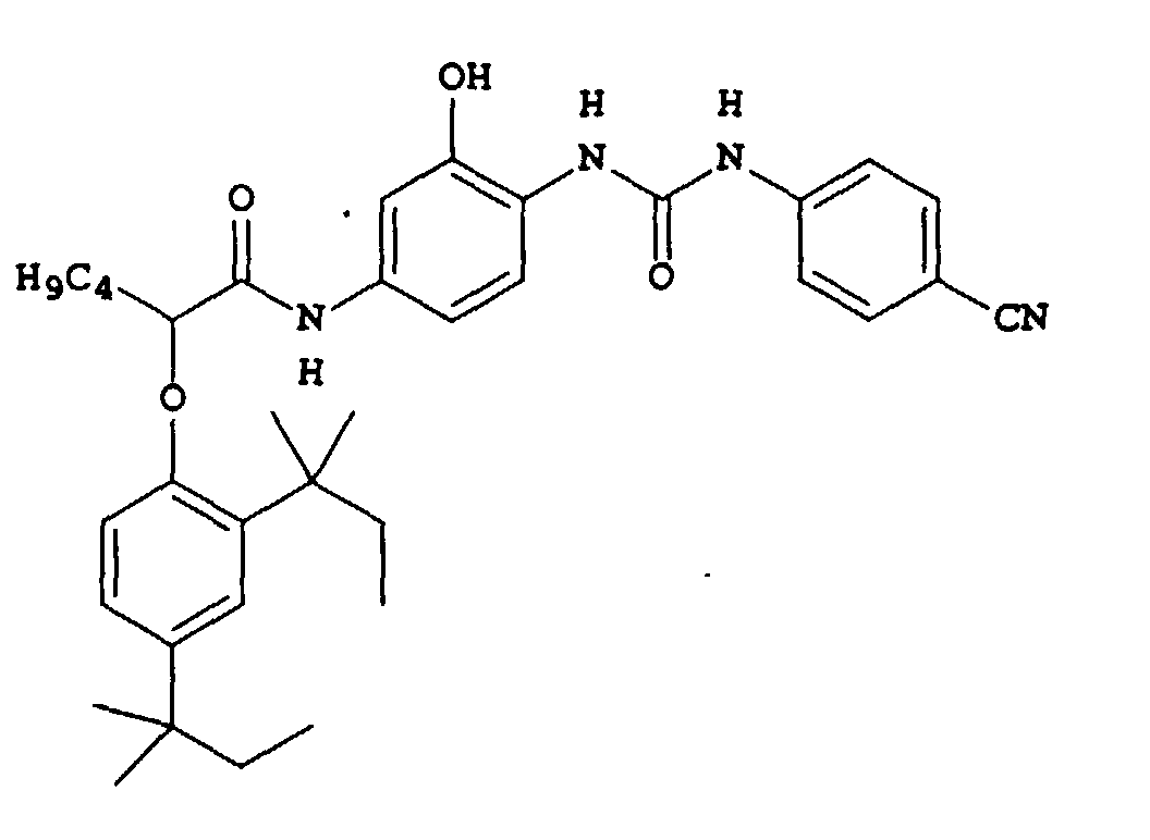
- C-2
-

- M-1
-
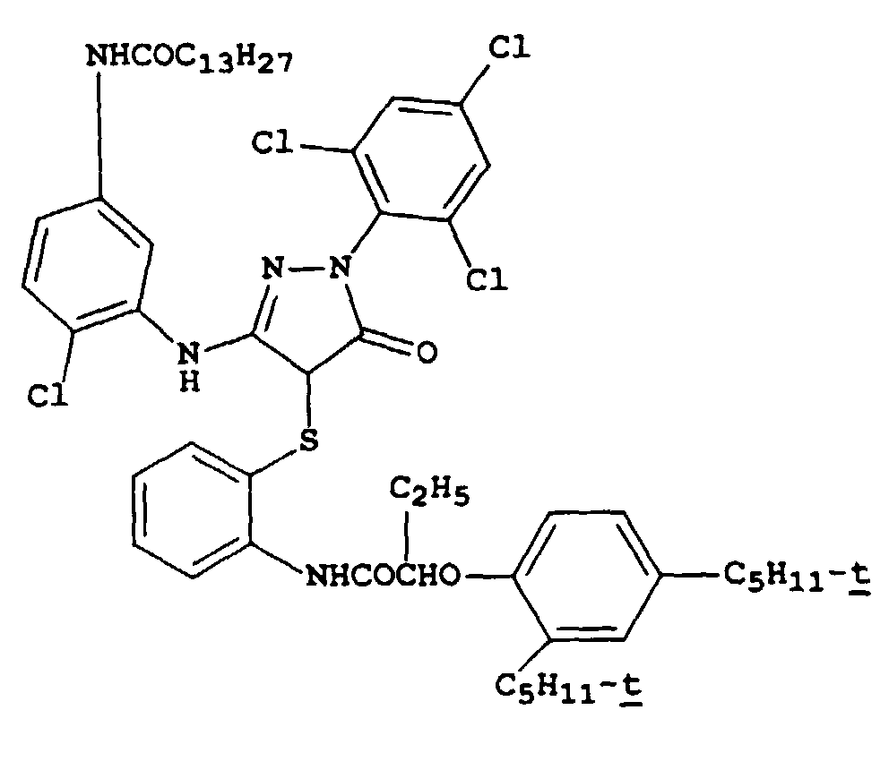
- Y-1
-

- D-1
-

- D-2
-
- D-3
-

- D-4
-

- D-5
-

- D-6
-

- D-7
-
- CM-1
-

- MM-1
-

- MM-2
-
- MD-1
-

- CD-1
-
- B-1
-

- YD-1
-
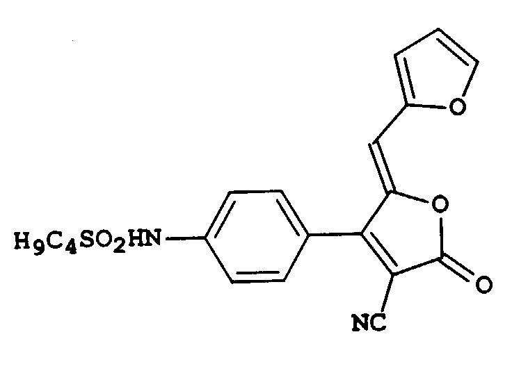
- UV-1
- UV-2

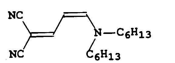
- S-1
-
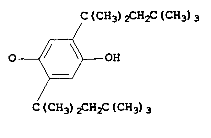
- S-2
-
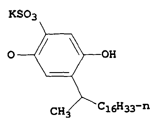
- S-3
-

- SD-1
-
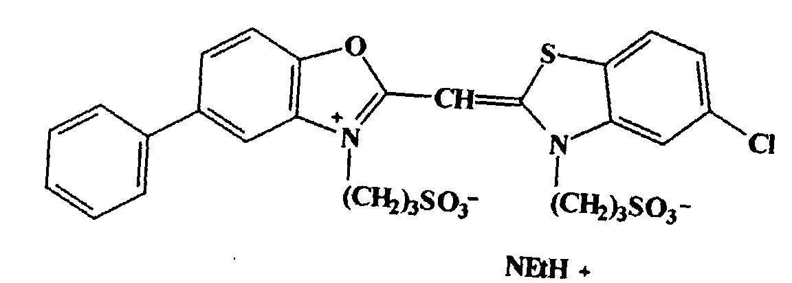
- SD-2
-
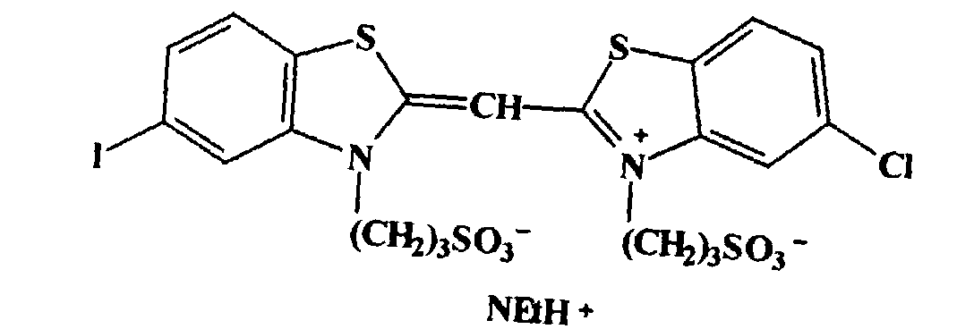
- SD-3
-

- SD-4
-

- SD-5
-


- SD-6
- SD-7
-
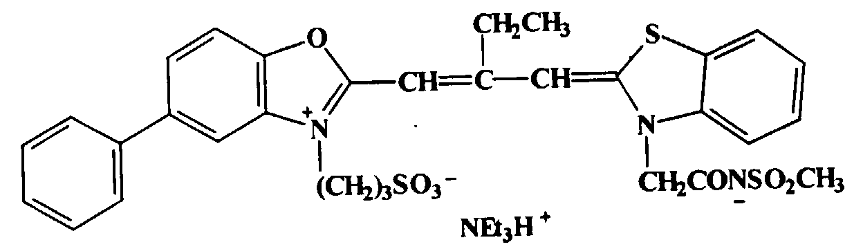
- SD-8
-

- SD-9
-

- SD- 10
-
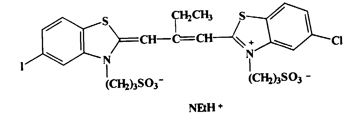
- SD-11
-
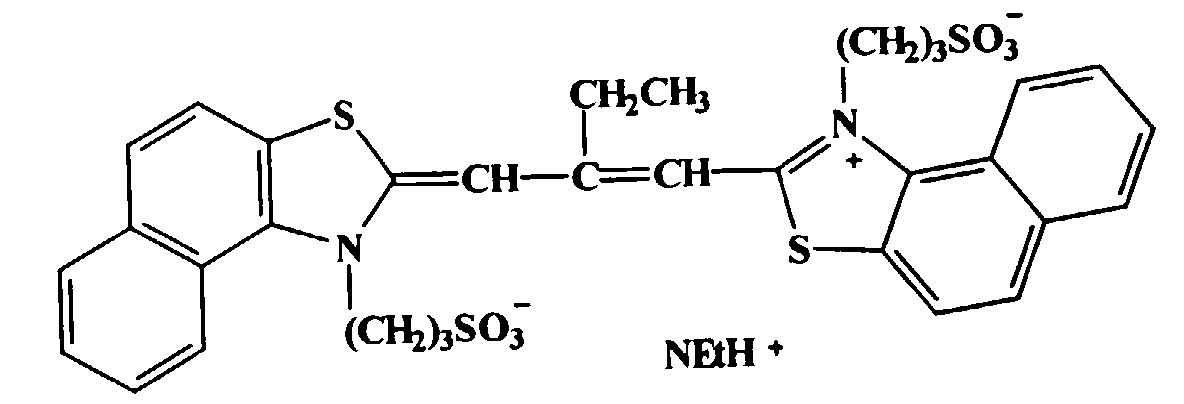
- SD-12
-

- SD-13
-
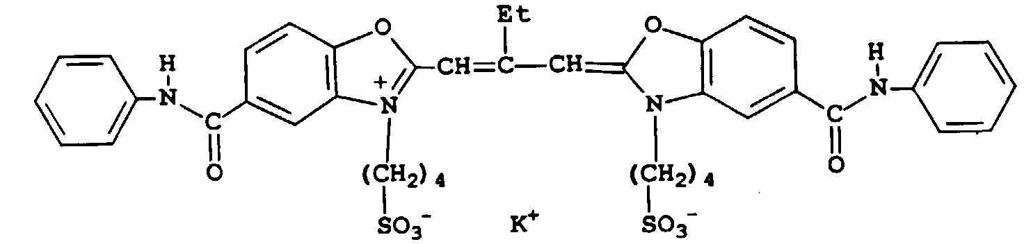
- SD-14
-

- SD-15
-
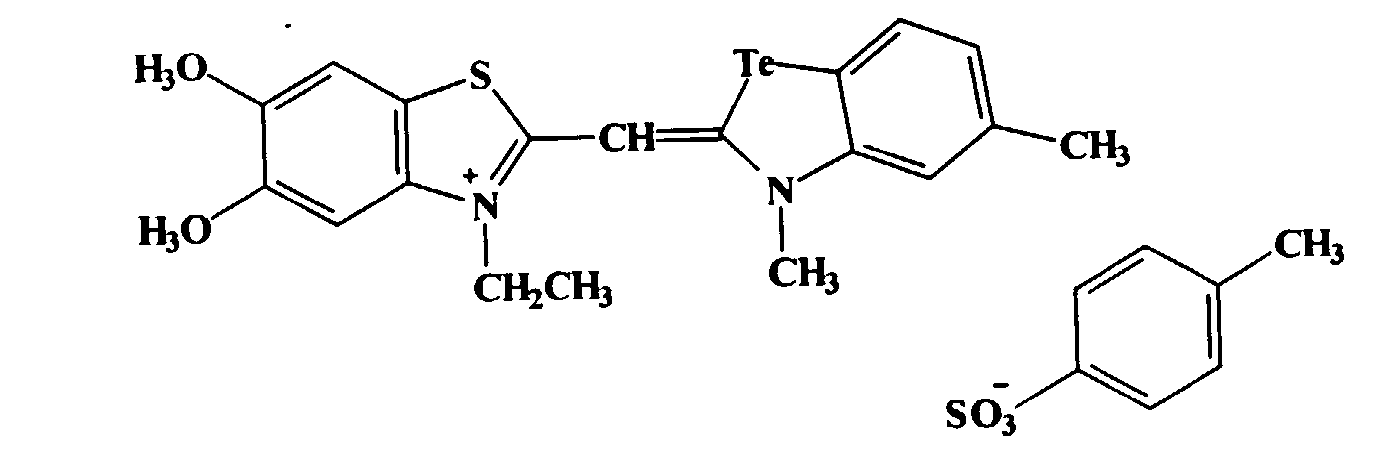
- SD-16
-
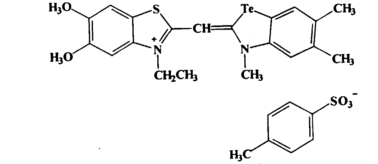
- SD-17
-
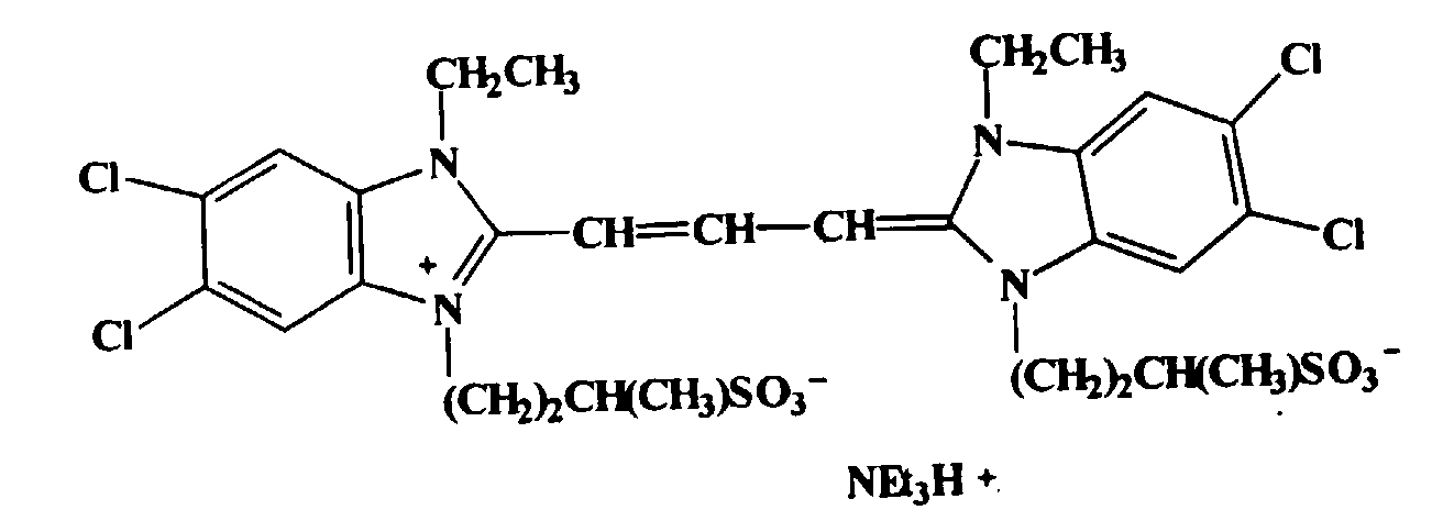
- SD-18
-
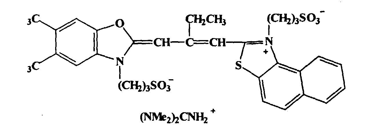
- SD-19
-
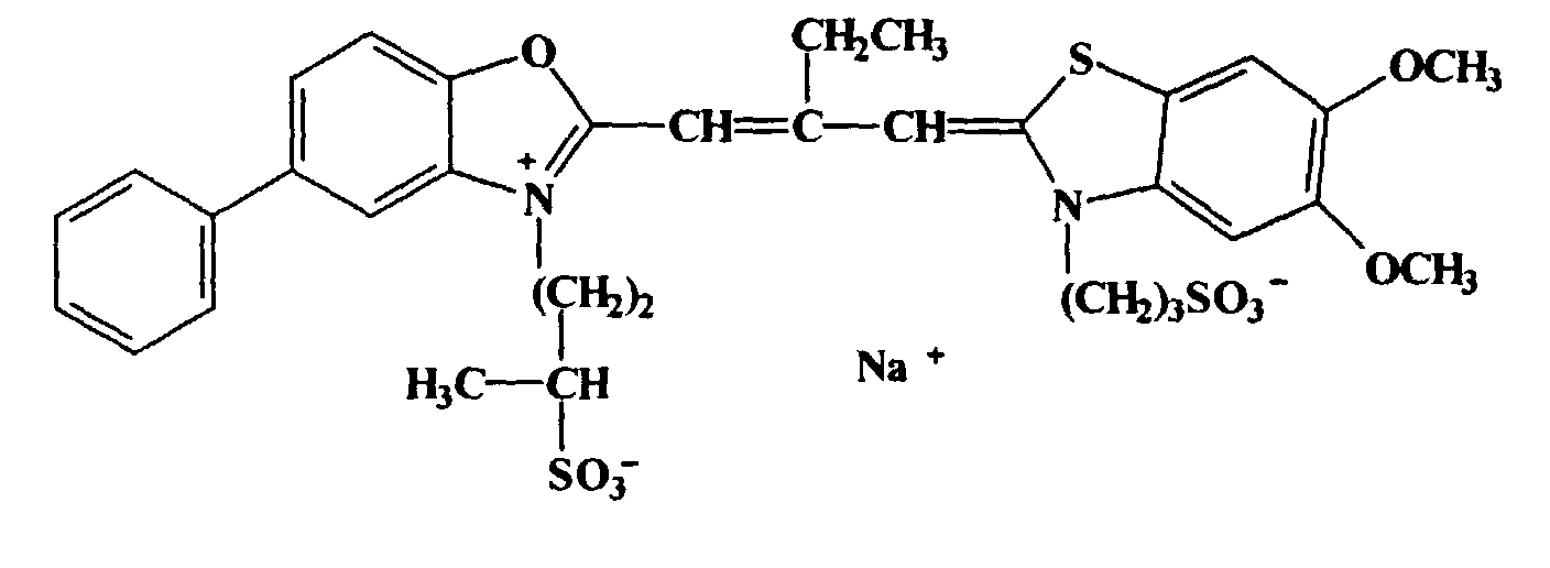
- Silver iodobromide tabular grain emulsions EC-01, EC-02, EC-03, EC-04, and EC-05 were provided having the significant grain characteristics set out in Table 1-1 below. Tabular grains accounted for greater than 70 percent of total grain projected area in all instances. Each of Emulsions EC-01 through EC-05 were optimally sulfur and gold sensitized. In addition, these emulsions were optimally spectrally sensitized with SD-08, SD-07, SD-09, SD-10, and SD-11 in a 40 : 31 : 18 : 7 : 4 molar ratio. The wavelength of peak light absorption for all emulsions was around 570 nm, and the half-peak absorption bandwidth was around 100 nm.
Emulsion size and iodide content Emulsion Average grain ECD (µm) Average grain thickness, (µm) Average Aspect Ratio Average Iodide Content (mol %) EC-01 2.20 0.12 18.3 3.9 EC-02 1.30 0.10 13.0 3.7 EC-03 0.90 0.12 7.5 3.7 EC-04 0.52 0.12 4.3 3.7 EC-05 0.57 0.07 8.1 1.3 - Silver iodobromide tabular grain emulsions EM-01, EM-02, EM-03, and EM-04 were provided having the significant grain characteristics set out in 1-2 below. Tabular grains accounted for greater than 70 percent of total grain projected area in all instances. Each of Emulsions EM-01 through EM-04 were optimally sulfur and gold sensitized. In addition, emulsions EM-01 and EM-02 were optimally spectrally sensitized with SD-04, SD-05, SD-06, and SD-07 in a 39.4 : 39.4 : 13.4: 7.8 molar ratio. Emulsions EM-03 and EM-04 were optimally spectrally sensitized with SD-04, SD-05, SD-06, and SD-07 in a 32.5 : 32.5 : 20 : 15 molar ratio. The wavelength of peak light absorption for all emulsions was around 540 nm, and the half-peak absorption bandwidth was around 75 nm. Substantial absorption was provided at 520, 550, and 560 nm.
Emulsion size and iodide content Emulsion Average grain ECD (µm) Average grain thickness, (µm) Average Aspect Ratio Average Iodide Content (mol %) EM-01 1.50 0.29 5.2 3.6 EM-02 1.60 0.24 6.7 3.6 EM-03 0.90 0.12 7.5 3.7 EM-04 0.57 0.07 8.1 1.3 - Silver iodobromide tabular grain emulsions EY-01, EY-02, EY-03, EY-04, and EY-05 were provided having the significant grain characteristics set out in Table 1-3 below. Tabular grains accounted for greater than 70 percent of total grain projected area in all instances. Each of Emulsions EY-01 through EY-05 were optimally sulfur and gold sensitized. In addition, these emulsions were optimally spectrally sensitized with SD-01, SD-02, and SD-03 in a 49 : 31 : 20 molar ratio. The wavelength of peak light absorption for all emulsions was around 456 nm, and the half-peak dye absorption bandwidth was around 50 nm.
Emulsion size and iodide content Emulsion Average grain ECD (µm) Average grain thickness, (µm) Average Aspect Ratio Average Iodide Content (mol %) EY-01 4.10 0.13 31.5 3.7 EY-02 2.20 0.12 18.3 3.9 EY-03 1.30 0.10 13.0 3.7 EY-04 0.52 0.12 4.3 3.7 EY-05 0.57 0.07 8.1 1.3 - Silver iodobromide tabular grain emulsions EC-06, EC-07, EC-08, and EC-09 were provided having the significant grain characteristics set out in Table 1-4 below. Tabular grains accounted for greater than 70 percent of total grain projected area in all instances. Each of Emulsions EC-06 through EC-09 were optimally sulfur and gold sensitized. In addition, these emulsions were optimally spectrally sensitized with SD-09 and SD-10 in a 2:1 molar ratio. The wavelength of peak light absorption for all emulsions was around 628 nm, and the half-peak absorption bandwidth was around 44 nm.
Emulsion size and iodide content Emulsion Average grain ECD (µm) Average grain thickness, (µm) Average Aspect Ratio Average Iodide Content (mol %) EC-06 2.60 0.12 21.7 3.7 EC-07 1.30 0.12 10.8 4.1 EC-08 0.55 0.08 6.9 1.5 EC-09 0.66 0.12 5.5 4.1 - Silver iodobromide tabular grain emulsions EM-05, EM-06, EM-07, and EM-08 were provided having the significant grain characteristics set out in Table 1-5 below. Tabular grains accounted for greater than 70 percent of total grain projected area in all instances. Each of Emulsions EM-05 through EM-08 were optimally sulfur and gold sensitized. In addition, emulsions EM-05 through EM-08 were optimally spectrally sensitized with SD-05 and SD-12 in a four and a half to one molar ratio of dye. The wavelength of peak light absorption for all emulsions was around 545nm, and the half-peak dyed absorption bandwidth was around 48 run for all emulsions.
Emulsion size and iodide content Emulsion Average grain ECD (µm) Average grain thickness, (µm) Average Aspect Ratio Average Iodide Content (mol %) EM-05 2.50 0.14 17.9 4.1 EM-06 1.20 0.11 10.9 4.1 EM-07 0.92 0.12 7.7 4.1 EM-08 0.81 0.12 6.8 2.6 - Silver iodobromide tabular grain emulsions EY-06, EY-07, EY-08, and EY-09 were provided having the significant grain characteristics set out in Table 1-6 below. Tabular grains accounted for greater than 70 percent of total grain projected area in all instances. Emulsion EY-06, a thick conventional grain was also provided. Each of Emulsions EY-06 through EY-09 were optimally sulfur and gold sensitized. In addition, these emulsions were optimally spectrally sensitized with SD-01 and SD-02 in a one to one molar ratio. The wavelength of peak light dye absorption for all emulsions was around 462 nm, and a second peak was present at around 442 nm. The half-peak dyed absorption bandwidth was around 45 nm for all emulsions.
Emulsion size and iodide content Emulsion Average grain ECD (µm) Average grain thickness, (µm) Average Aspect Ratio Average Iodide Content (mol %) EY-06 1.04 Not applicable Not applicable 9.0 EY-07 1.30 0.14 9.3 4.1 EY-08 0.77 0.14 5.5 1.5 EY-09 0.55 0.08 6.9 1.5 - Silver iodobromide tabular grain unsensitized emulsions EC-10, EC-11, EC-12, EC-13, and EC-14 were identical to the unsensitized EC-01, EC-02, EC-03, EC-04, and EC-05, respectively. Each of emulsions EC-10 through EC-14 were optimally sulfur and gold sensitized. In addition, these emulsions were optimally spectrally sensitized with SD-05, SD-08, SD-07, SD-09, SD-10, and SD-11 in a 10 : 55 : 15 : 8 : 8 : 4 molar ratio. The wavelength of peak light absorption for all emulsions was around 567 nm, and the half-peak absorption bandwidth was around 70 nm.
- Silver iodobromide tabular grain emulsions unsensitized EC-15, EC-16, EC-17, EC-18, and EC-19 were identical to the unsensitized EC-01, EC-02, EC-03, EC-04, and EC-05, respectively. Each of emulsions EC-15 through EC-19 were optimally sulfur and gold sensitized. In addition, these emulsions were optimally spectrally sensitized with SD-17, SD-18, and SD-11 in a 55 : 35 : 10 molar ratio. The wavelength of peak light absorption for all emulsions was around 578, with a second peak at 610nm. The half-peak absorption bandwidth was over 59 nm.
- Silver iodobromide tabular grain unsensitized emulsions EC-20, EC-21, EC-22, EC-23, and EC-24 were identical to the unsensitized EC-01, EC-02, EC-03, EC-04, and EC-05, respectively. Each of emulsions EC-20 through EC-24 were optimally sulfur and gold sensitized. In addition, these emulsions were optimally spectrally sensitized with SD-10 and SD-19 in a 9 : 1 molar ratio. The wavelength of peak light absorption for all emulsions was around 653 nm, and the half-peak absorption bandwidth was around 36 nm.
- Silver iodobromide tabular grain emulsions EM-09, EM-10, EM-11, and EM-12 were provided having the significant grain characteristics set out in Table 1-7 below. Tabular grains accounted for greater than 70 percent of total grain projected area in all instances. Each of Emulsions EM-09 through EM-12 were optimally sulfur and gold sensitized. In addition, the emulsions were optimally spectrally sensitized with SD-13, SD-05, SD-06, and SD-07 in a 15 : 50 : 20 : 15 molar ratio. The wavelength of peak light absorption for all emulsions was around 558 nm, and the half-peak absorption bandwidth was around 73 nm. Substantial absorption was provided at 520, 550, and 560 nm.
Emulsion size and iodide content Emulsion Average grain ECD (µm) Average grain thickness, (µm) Average Aspect Ratio Average Iodide Content (mol %) EM-09 2.40 0.12 20.0 3.6 EM-10 1.30 0.10 13.0 3.7 EM-11 0.90 0.12 7.5 3.7 EM-11 0.57 0.07 8.1 1.3 - Silver iodobromide tabular grain emulsions EM-13, EM-14, EM-15, and EM-16 were provided having the significant grain characteristics set out in Table 1-8 below. Tabular grains accounted for greater than 70 percent of total grain projected area in all instances. Each of emulsions EM-13 through EM-16 were optimally sulfur and gold sensitized. In addition, the emulsions EM-13 and EM-14 were optimally spectrally sensitized with SD-14, SD-05, and SD-15 in a 23.6 : 38.2 : 38.2 molar ratio. Emulsions EM-15 and EM-16 were optimally spectrally sensitized with SD-14, SD-05, and SD-16 in a 23.6 : 38.2 : 38.2 molar ratio. The wavelength of peak light absorption for all emulsions was around 542 nm, and the half-peak absorption bandwidth was around 25 nm.
Emulsion size and iodide content Emulsion Average grain ECD (µm) Average grain thickness, (µm) Average Aspect Ratio Average Iodide Content (mol %) EM-13 1.40 0.30 4.7 3.5 EM-14 0.70 0.34 2.1 3.5 EM-15 0.90 0.12 7.5 3.7 EM-16 0.57 0.07 8.1 1.3 - Silver iodobromide tabular grain emulsions EY-10, EY-11, EY-12, and EY-13 were provided having the significant grain characteristics set out in Table 1-9 below. Tabular grains accounted for greater than 70 percent of total grain projected area in all instances. Each of Emulsions EY-10 through EY-13 were optimally sulfur and gold sensitized. In addition, these emulsions were optimally spectrally sensitized with SD-01 and SD-02 in a 1 : 1 molar ratio. The wavelength of peak light dye absorption for all emulsions was around 462 nm, and a second peak was present at around 442 nm. The half-peak dyed absorption bandwidth was around 45 nm for all emulsions.
Emulsion size and iodide content Emulsion Average grain ECD (µm) Average grain thickness, (µm) Average Aspect Ratio Average Iodide Content (mol %) EY-10 2.2 0.12 18.3 3.9 EY-11 1.30 0.10 13.0 3.7 EY-12 0.52 0.12 4.3 3.7 EY-13 0.57 0.07 8.1 1.3 - All coating coverages are reported in parenthesis in terms of g/m2, except as otherwise indicated. Silver halide coating coverages are reported in terms of silver.
- The slower, mid-speed, and faster emulsion layers within each of the blue (BU), green (GU), and red (RU) recording layer units are indicated by the prefix S, M, and F, respectively.
- This sample was prepared by applying the following layers in the sequence recited to a transparent film support of cellulose triacetate with conventional subbing layers, with the red recording layer unit coated nearest the support. The side of the support to be coated had been prepared by the application of gelatin subbing.
Layer 1: AHU Black colloidal silver sol (0.151) UV-1 (0.075) UV-2 (0.108) Oxidized developer scavenger S-1 (0.161) Compensatory printing density cyan dye CD-1 (0.016) Compensatory printing density magenta dye MD-1 (0.038) Compensatory printing density yellow dye MM-2 (0.178) HBS-1 (0.105) HBS-2 (0.341) HBS-4 (0.038) HBS-7 (0.011) Disodium salt of 3,5-disulfocatechol (0.228) Gelatin (2.044) Layer 2: SRU This layer was comprised of a blend of a lower, medium, and higher (lower, medium, and higher grain ECD) sensitivity, red-sensitized tabular silver iodobromide emulsions. Emulsion EC-03, silver content (0.430) Emulsion EC-04, silver content (0.215) Emulsion EC-05, silver content (0.269) Bleach accelerator releasing coupler B-1 (0.057) Oxidized developer scavenger S-3 (0.183) Development inhibitor releasing coupler D-7 (0.013) Cyan dye forming coupler C-1 (0.344) Cyan dye forming coupler C-2 (0.038) HBS-2 (0.026) HBS-5 (0.118) HBS-6 (0.120) TAI (0.015) Gelatin (1.679) Layer 3: MRU Emulsion EC-02, silver content (1.076) Bleach accelerator releasing coupler B-1 (0.022) Development inhibitor releasing coupler D-1 (0.011) Development inhibitor releasing coupler D-7 (0.013) Oxidized developer scavenger S-3 (0.183) Cyan dye forming coupler C-1 (0.086) Cyan dye forming coupler C-2 (0.086) HBS-1 (0.044) HBS-2 (0.026) HBS-5 (0.097) HBS-6 (0.074) TAI (0.021) Gelatin (1.291) Layer 4: FRU Emulsion EC-01, silver content (1.291) Development inhibitor releasing coupler D-1 (0.011) Development inhibitor releasing coupler D-7 (0.011) Oxidized developer scavenger S-1 (0.014) Cyan dye forming coupler C-1 (0.065) Cyan dye forming coupler C-2 (0.075) HBS-1 (0.044) HBS-2 (0.022) HBS-4 (0.021) HBS-5 (0.161) TAI (0.021) Gelatin (1.076) Layer 5: Interlayer Oxidized developer scavenger S-1 (0.086) HBS-4 (0.129) Gelatin (0.538) Layer 6: SGU This layer was comprised of a blend of a lower and higher (lower and higher grain ECD) sensitivity, green-sensitized tabular silver iodobromide emulsions. Emulsion EM-03, silver content (0.323) Emulsion EM-04, silver content (0.215) Bleach accelerator releasing coupler B-1 (0.012) Development inhibitor releasing coupler D-7 (0.011) Oxidized developer scavenger S-3 (0.183) Magenta dye forming coupler M-1 (0.301) Stabilizer ST-1 (0.060) HBS-1 (0.241) HBS-2 (0.022) HBS-6 (0.061) TAI (0.004) Gelatin (1.108) Layer 7: MGU Emulsion EM-02, silver content (0.968) Bleach accelerator releasing coupler B-1 (0.005) Development inhibitor releasing coupler D-1 (0.011) Development inhibitor releasing coupler D-7 (0.011) Oxidized developer scavenger S-1 (0.011) Oxidized developer scavenger S-3 (0.183) Magenta dye forming coupler M-1 (0.113) Stabilizer ST-1 (0.023) HBS-1 (0.133) HBS-2 (0.022) HBS-4 (0.016) HBS-6 (0.053) TAI (0.016) Gelatin (1.399) Layer 8: FGU Emulsion EM-01, silver content (0.968) Development inhibitor releasing coupler D-1 (0.009) Development inhibitor releasing coupler D-7 (0.011) Oxidized developer scavenger S-1 (0.011) Magenta dye forming coupler M-1 (0.097) Stabilizer ST-1 (0.019) HBS-1 (0.112) HBS-2 (0.022) HBS-4 (0.016) TAI (0.009) Gelatin (1.399) Layer 9: Yellow Filter Layer Yellow filter dye YD-1 (0.032) Oxidized developer scavenger S-1 (0.086) HBS-4 (0.129) Gelatin (0.646) Layer 10: SBU This layer was comprised of a blend of a lower, lower-medium, medium, and higher (lower, lower-medium, medium, and higher grain ECD) sensitivity, blue-sensitized tabular silver iodobromide emulsions. Emulsion EY-02, silver content (0.323) Emulsion EY-03, silver content (0.247) Emulsion EY-04, silver content (0.215) Emulsion EY-05, silver content (0.269) Bleach accelerator releasing coupler B-1 (0.003) Development inhibitor releasing coupler D-7 (0.011) Oxidized developer scavenger S-3 (0.183) Yellow dye forming coupler Y-1 (0.710) HBS-2 (0.022) HBS-5 (0.151) HBS-6 (0.050) TAI (0.016) Gelatin (1.872) Layer 11: FBU Emulsion EY-01, silver content (0.699) Bleach accelerator releasing coupler B-1 (0.005) Development inhibitor releasing coupler D-7 (0.013) Yellow dye forming coupler Y-1 (0.140) HBS-2 (0.026) HBS-5 (0.118) HBS-6 (0.007) TAI (0.011) Gelatin (1.291) Layer 12: Protective Overcoat Layer Polymethylmethacrylate matte beads (0.005) Soluble polymethylmethacrylate matte beads (0.054) Unsensitized silver bromide Lippmann emulsion (0.215) Dye UV-1 (0.108) Dye UV-2 (0.216) Silicone lubricant (0.040) HBS-1 (0.151) HBS-7 (0.108) Gelatin (1.237) - This film was hardened at the time of coating with 1.75% by weight of total gelatin of hardener H-1. Surfactants, coating aids, soluble absorber dyes, antifoggants, stabilizers, antistatic agents, biostats, biocides, and other addenda chemicals were added to the various layers of this sample, as is commonly practiced in the art.
- This sample was prepared by applying the following layers in the sequence recited to a transparent film support of cellulose triacetate with conventional subbing layers, with the red recording layer unit coated nearest the support. The side of the support to be coated had been prepared by the application of gelatin subbing.
Layer 1: AHU Black colloidal silver sol (0.107) UV-1 (0.075) UV-2 (0.075) Oxidized developer scavenger S-1 (0.161) Compensatory printing density cyan dye CD-1 (0.034) Compensatory printing density magenta dye MD-1 (0.013) Compensatory printing density yellow dye MM-2 (0.095) HBS-1 (0.105) HBS-2 (0.433) HBS-4 (0.013) Disodium salt of 3,5-disulfocatechol (0.215) Gelatin (2.152) Layer 2: SRU This layer was comprised of a blend of a lower and higher (lower and higher grain ECD) sensitivity, red-sensitized tabular silver iodobromide emulsions respectively. Emulsion EC-09, silver content (0.355) Emulsion EC-08, silver content (0.328) Bleach accelerator releasing coupler B-1 (0.075) Development inhibitor releasing coupler D-5 (0.015) Cyan dye forming coupler C-1 (0.359) HBS-2 (0.405) HBS-6 (0.098) TAI (0.011) Gelatin (1.668) Layer 3: MRU Emulsion EC-07, silver content (1.162) Bleach accelerator releasing coupler B-1 (0.005) Development inhibitor releasing coupler D-5 (0.016) Cyan dye forming magenta colored coupler CM-1 (0.059) Cyan dye forming coupler C-1 (0.207) HBS-2 (0.253) HBS-6 (0.007) TAI (0.019) Gelatin (1.291) Layer 4: FRU Emulsion EC-06, silver content (1.060) Bleach accelerator releasing coupler B-1 (0.005) Development inhibitor releasing coupler D-5 (0.027) Development inhibitor releasing coupler D-1 (0.048) Cyan dye forming magenta colored coupler CM-1 (0.022) Cyan dye forming coupler C-1 (0.323) HBS-1 (0.194) HBS-2 (0.274) HBS-6 (0.007) TAI (0.010) Gelatin (1.291) Layer 5: Interlayer Oxidized developer scavenger S-1 (0.086) HBS-4 (0.129) Gelatin (0.538) Layer 6: SGU This layer was comprised of a blend of a lower and higher (lower and higher grain ECD) sensitivity, green-sensitized tabular silver iodobromide emulsions respectively. Emulsion EM-08, silver content (0.251) Emulsion EM-07, silver content (0.110) Magenta dye forming yellow colored coupler MM-1 (0.054) Magenta dye forming coupler M-1 (0.339) Stabilizer ST-1 (0.034) HBS-1 (0.413) TAI (0.006) Gelatin (1.184) Layer 7: MGU This layer was comprised of a blend of a lower and higher (lower and higher grain ECD) sensitivity, green-sensitized tabular silver iodobromide emulsions. Emulsion EM-07, silver content (0.091) Emulsion EM-06, silver content (1.334) Development inhibitor releasing coupler D-6 (0.032) Magenta dye forming yellow colored coupler MM-1 (0.118) Magenta dye forming coupler M-1 (0.087) Oxidized developer scavenger S-2 (0.018) HBS-1 (0.315) HBS-2 (0.032) Stabilizer ST-1 (0.009) TAI (0.023) Gelatin (1.668) Layer 8: FGU Emulsion EM-05, silver content (0.909) Development inhibitor releasing coupler D-3 (0.003) Development inhibitor releasing coupler D-7 (0.032) Oxidized developer scavenger S-2 (0.023) Magenta dye forming yellow colored coupler MM-1 (0.054) Magenta dye forming coupler M-1 (0.113) HBS-1 (0.216) HBS-2 (0.064) Stabilizer ST-1 (0.011) TAI (0.011) Gelatin (1.405) Layer 9: Yellow Filter Layer Yellow filter dye YD-1 (0.054) Oxidized developer scavenger S-1 (0.086) HBS-4 (0.129) Gelatin (0.646) Layer 10: SBU This layer was comprised of a blend of a lower, medium, and higher (lower, medium, and higher grain ECD) sensitivity, blue-sensitized tabular silver iodobromide emulsions. Emulsion EY-09, silver content (0.140) Emulsion EY-08, silver content (0.247) Emulsion EY-07, silver content (0.398) Development inhibitor releasing coupler D-5 (0.027) Development inhibitor releasing coupler D-4 (0.054) Yellow dye forming coupler Y-1 (1.022) Cyan dye forming coupler C-1 (0.027) Bleach accelerator releasing coupler B-1 (0.011) HBS-1 (0.592) HBS-2 (0.108) HBS-6 (0.014) TAI (0.014) Gelatin (2.119) Layer 11: FBU This layer was comprised of a blue-sensitized tabular silver iodobromide emulsion containing 9.0 M% iodide, based on silver. Emulsion EY-06, silver content (0.699) Unsensitized silver bromide Lippmann emulsion (0.054) Yellow dye forming coupler Y-1 (0.473) Development inhibitor releasing coupler D-4 (0.086) Bleach accelerator releasing coupler B-1 (0.005) HBS-1 (0.280) HBS-6 (0.007) TAI (0.012) Gelatin (1.183) Layer 12: Ultraviolet Filter Layer Dye UV-1 (0.108) Dye UV-2 (0.108) Unsensitized silver bromide Lippmann emulsion (0.215) HBS-1 (0.151) Gelatin (0.699) Layer 13: Protective Overcoat Layer Polymethylmethacrylate matte beads (0.005) Soluble polymethylmethacrylate matte beads (0.108) Silicone lubricant (0.039) Gelatin (0.882) - This film was hardened at the time of coating wit 1.80% by weight of total gelatin of hardener H-1. Surfactants, coating aids, soluble absorber dyes, antifoggants, stabilizers, antistatic agents, biostats, biocides, and other addenda chemicals were added to the various layers of this sample, as is commonly practiced in the art.
- Sample 103 (Invention) color photographic recording material for color negative development was prepared exactly as above in Sample 101, except where noted below.
Layer 10: SBU Changes Emulsion EY-05, silver content (0.000) Emulsion EY-04, silver content (0.000) Emulsion EY-03, silver content (0.000) Emulsion EY-02, silver content (0.000) Emulsion EY-13, silver content (0.269) Emulsion EY-12, silver content (0.215) Emulsion EY-11, silver content (0.247) Emulsion EY-10, silver content (0.323) Layer 11: FBU Changes Emulsion EY-01 (0.000) Emulsion EY-06 (0.699) - Sample 104 (Invention) color photographic recording material for color negative development was prepared exactly as above in Sample 101, except where noted below.
Layer 2: SRU Changes Emulsion EC-03, silver content (0.000) Emulsion EC-04, silver content (0.000) Emulsion EC-05, silver content (0.000) Emulsion EC-12, silver content (0.430) Emulsion EC-13, silver content (0.215) Emulsion EC-14, silver content (0.269) Layer 3: MRU Changes Emulsion EC-02, silver content (0.000) Emulsion EC-11, silver content (1.076) Layer 4: FRU Changes Emulsion EC-01, silver content (0.000) Emulsion EC-10, silver content (01.291) Layer 6: SGU Changes Emulsion EM-03, silver content (0.000) Emulsion EM-04, silver content (0.000) Emulsion EM-11, silver content (0.323) Emulsion EM-12, silver content (0.215) Layer 7: MGU Changes Emulsion EM-02, silver content (0.000) Emulsion EM-10, silver content (0.968) Layer 8: FGU Changes Emulsion EM-01, silver content (0.000) Emulsion EM-09, silver content (0.968) - Sample 105 (Comparative control) color photographic recording material for color negative development was prepared exactly as above in Sample 103, except where noted below.
Layer 2: SRU Changes Emulsion EC-03, silver content (0.000) Emulsion EC-04, silver content (0.000) Emulsion EC-05, silver content (0.000) Emulsion EC-17, silver content (0.430) Emulsion EC-18, silver content (0.215) Emulsion EC-19, silver content (0.269) Layer 3: MRU Changes Emulsion EC-02, silver content (0.000) Emulsion EC-16, silver content (1.076) Layer 4: FRU Changes Emulsion EC-01, silver content (0.000) Emulsion EC-15, silver content (1.291) Layer 6: SGU Changes Emulsion EM-03, silver content (0.000) Emulsion EM-04, silver content (0.000) Emulsion EM-15, silver content (0.323) Emulsion EM-16, silver content (0.215) Layer 7: MGU Changes Emulsion EM-02, silver content (0.000) Emulsion EM-14, silver content (0.968) Layer 8: FGU Changes Emulsion EM-01, silver content (0.000) Emulsion EM-13, silver content (0.968) - Sample 106 (Comparative control) color photographic recording material for color negative development was prepared exactly as above in Sample 101, except where noted below.
Layer 6: SGU Changes Emulsion EM-03, silver content (0.000) Emulsion EM-04, silver content (0.000) Emulsion EM-15, silver content (0.323) Emulsion EM-16, silver content (0.215) Layer 7: MGU Changes Emulsion EM-02, silver content (0.000) Emulsion EM-14, silver content (0.968) Layer 8: FGU Changes Emulsion EM-01, silver content (0.000) Emulsion EM-13, silver content (0.968) - Sample 107 (Comparative control) color photographic recording material for color negative development was prepared exactly as above in Sample 101, except where noted below.
Layer 2: SRU Changes Emulsion EC-03, silver content (0.000) Emulsion EC-04, silver content (0.000) Emulsion EC-05, silver content (0.000) Emulsion EC-22, silver content (0.430) Emulsion EC-23, silver content (0.215) Emulsion EC-24, silver content (0.269) Layer 3: MRU Changes Emulsion EC-02, silver content (0.000) Emulsion EC-21, silver content (1.076) Layer 4: FRU Changes Emulsion EC-01, silver content (0.000) Emulsion EC-20, silver content (1.291) - The sensitivities over the visible spectrum of the individual color units of the photographic recording materials, Samples 101―107, were determined in 5-nm increments using nearly monochromatic light of carefully calibrated output from 360 to 715 nm. Photographic recording materials Samples 101―107 were individually exposed for 1/100 of a second to white light from a tungsten light source of 3000K color temperature that was filtered by a Daylight Va filter to 5500K and by a monochromator with a 4-nm bandpass resolution through a graduated 0―4.0 density step tablet with 0.3-density step increments to determine their speed. The samples were then processed using the KODAK FLEXICOLOR™ C-41 Process, as described by The British Journal of Photography Annual of 1988, pp. 196―198. Another description of the use of the FLEXICOLOR™ process is provided by Using Kodak Flexicolor Chemicals, Kodak Publication No. Z-131, Eastman Kodak Company, Rochester, NY..
- Following processing and drying, Samples 101―107 were subjected to Status M densitometry and their sensitometric performance over the visible spectrum was characterized. The exposure required to produce a density increase of 0.20 above Dmin was determined for the color recording units at each 5-nm increment exposed. The exposure distribution for each of the red, green and blue responsivities was normalized by its maximum sensitivity to convert each of the 5-nm sample sensitivities to relative sensitivities for plotting as a function of wavelength, as in Fig. 1 and 2. A second set of speeds was generated by taking the Status M densitometry and transforming it to analytical densities using a 3x3 matrix treatment appropriate for the image dye set according to methods disclosed in the art cited earlier. . The exposure required to produce a analytical density increase of 0.20 above Dmin was determined for the color recording units at each 5-nm increment exposed. The exposure distribution for each of the red, green and blue responsivities was normalized by its maximum sensitivity to convert each of the 5-nm sample sensitivities to relative sensitivities for plotting, as also in Fig. 1 and 2, and Fig. 3 to 9 as well.
- The spectral sensitivity response of the photographic recording materials was also used to determine the relative colorimetric accuracy of color negative materials Samples 101―107 in recording a particular diverse set of 200 different color patches according to the method disclosed by Giorgianni et al, in U.S. Patent 5,582,961. The computed color error variance is included in Table 3-1. This error value relates to the color difference between the CIELAB space coordinates of the specified set of test colors and the space coordinates resulting from a specific transformation of the test colors as rendered by the film. In particular, the test patch input spectral reflectance values for a given light source are convolved with the sample photographic materials' spectral sensitivity response to estimate colorimetric recording capability. It should be noted that the computed color error is sensitive to the responses of all three input color records, and an improved response by one record may not overcome the responses of one or two other limiting color records. A color error difference of at least 1 unit corresponds to a significant difference in color recording accuracy. The points divergence of the comparative controls from the requirements of the invention are highlighted in bold.
- When red emulsion unit maximum sensitivity greater than 620 nm was employed, as in conventional optical print color negative films containing colored masking couplers (e.g. Sample 102, comparative control), a substantial color error of 10 or higher resulted, indicating quite significant metameric color failure at the time of capture of the scene light exposures. The use of more hypsochromic red spectral sensitivities with peak response below 620 nm of and by itself was insufficient to produce colorimetrically accurate recording. Sample 105, which is representative of color matching function spectral sensitivity films of the art, provided the required wavelengths of maximum sensitivity, and appreciable overlap between the green and red recording unit's spectral sensitivity. But Sample 105 and 106 both provided green unit breadth of sensitivity under 65 nm and short green sensitivity at 520 nm well below 60%, and consequently inadequate color accuracy levels resulted.
- The use of more hypsochromic, broad green spectral sensitivities with peak response below 565 nm of and by itself was insufficient to produce colorimetrically accurate recording as well. The combination of maximum green sensitivity of between about 520 and 565 nm, overall half-maximum relative sensitivity bandwidth of greater than 65 nm, and relative sensitivity at 520 nm of at least 60% of maximum with a red emulsion unit maximum sensitivity of greater than 620 nm in Sample 107 likewise produced a high color error indicating poor color accuracy. Only when all of the requirements of the invention are met simultaneously does a marked reduction in color error variance occur which is indicative of much higher color recording fidelity (e.g. inventive Samples 101, 103, and 104). These Samples representing preferred embodiments of the invention are much better suited for providing image records of the incident scene light for electronic image processing into viewable form which have significantly reduced metameric color failure or fewer artifacts due to illuminant metamerism.

Claims (11)
- A color photographic element capable of producing dye images suitable for digital scanning comprised ofa support and, coated on the support, a plurality of hydrophilic colloid layers includinga blue recording emulsion layer unit capable of forming a dye image of a first hue,a green recording emulsion layer unit capable of forming a dye image of a second hue, anda red recording emulsion layer unit capable of forming a dye image of a third hue,
wherein,with the proviso that magenta colored filter materials are absent from the red recording emulsion layer unit.(1) the wavelength of maximum sensitivity of the red recording emulsion layer unit is between about 580 and 620 nm,(2) the wavelength of maximum sensitivity of the green recording emulsion layer unit is between about 520 and 565 nm,(3) the relative sensitivity of the green recording emulsion layer unit at 50% of the maximum sensitivity exhibits an overall breadth of at least about 65 nm, and(4) the relative sensitivity of the green recording emulsion layer unit at 520 nm is at least 60% of the maximum, - A color photographic element capable of producing dye images suitable for digital scanning according to claim 1 wherein the relative sensitivities of the green recording emulsion layer unit and of the red recording emulsion layer unit overlap between about 550 and 600 nm and the overlap is at least about 35% of the maximum relative sensitivity.
- A color photographic element capable of producing dye images suitable for digital scanning according to claim 1 wherein the relative sensitivity of the red recording emulsion layer unit at 560 nm is at least about 25% of the maximum sensitivity.
- A color photographic element capable of producing dye images suitable for digital scanning according to claim 1 wherein the wavelength of maximum sensitivity of the blue recording emulsion layer unit is between about 430 nm and 470 nm.
- A color photographic element capable of producing dye images suitable for digital scanning according to claim 1 wherein the recording layer units are substantially free of colored masking couplers.
- A color photographic element capable of producing dye images suitable for digital scanning according to claim 5 wherein the photographic recording material is a color negative film.
- A color photographic element capable of producing dye images suitable for digital scanning according to claim 1 wherein an interlayer is interposed between the green and red recording layer units with the proviso that the interlayer is substantially free of magenta colored filter materials.
- A color photographic element capable of producing dye images suitable for digital scanning according to claim 7 wherein magenta colored masking couplers are absent from the red recording emulsion layer unit.
- A color photographic element capable of producing dye images suitable for digital scanning according to claim 8 wherein the wavelength of maximum sensitivity of the blue recording emulsion layer unit is between about 430 nm and 470 nm.
- A color photographic element capable of producing dye images suitable for digital scanning according to claim 9 wherein the element is a color negative recording material.
- A color negative film capable of producing dye images suitable for digital scanning according to claim 10 wherein each blue recording layer unit contains a yellow dye-forming coupler, each green recording layer unit contains a magenta dye-forming coupler, and each red recording layer unit contains a cyan dye-forming coupler.
Applications Claiming Priority (2)
| Application Number | Priority Date | Filing Date | Title |
|---|---|---|---|
| US09/259,694 US6296994B1 (en) | 1999-03-01 | 1999-03-01 | Photographic elements for colorimetrically accurate recording intended for scanning |
| US259694 | 2008-10-28 |
Publications (1)
| Publication Number | Publication Date |
|---|---|
| EP1033620A1 true EP1033620A1 (en) | 2000-09-06 |
Family
ID=22985982
Family Applications (1)
| Application Number | Title | Priority Date | Filing Date |
|---|---|---|---|
| EP00200547A Withdrawn EP1033620A1 (en) | 1999-03-01 | 2000-02-17 | Photographic elements for colorimetrically accurate recording intended for scanning |
Country Status (4)
| Country | Link |
|---|---|
| US (1) | US6296994B1 (en) |
| EP (1) | EP1033620A1 (en) |
| JP (1) | JP2000250179A (en) |
| CN (1) | CN1265477A (en) |
Cited By (2)
| Publication number | Priority date | Publication date | Assignee | Title |
|---|---|---|---|---|
| EP1324127A1 (en) * | 2001-12-20 | 2003-07-02 | Eastman Kodak Company | A color negative element intended for scanning |
| CN102021983A (en) * | 2009-09-14 | 2011-04-20 | 金华成金属工程有限公司 | Heat insulation device with solar panel |
Families Citing this family (7)
| Publication number | Priority date | Publication date | Assignee | Title |
|---|---|---|---|---|
| WO2001057797A2 (en) * | 2000-02-03 | 2001-08-09 | Applied Science Fiction | Method, system and software for signal processing using sheep and shepherd artifacts |
| US6479226B2 (en) * | 2000-04-27 | 2002-11-12 | Konica Corporation | Silver halide color photographic light sensitive material |
| US6589721B1 (en) | 2001-12-20 | 2003-07-08 | Eastman Kodak Company | Method of developing a color negative element intended for scanning |
| US7029837B2 (en) * | 2003-12-11 | 2006-04-18 | Eastman Kodak Company | Photographic film element containing an emulsion with dual peek green responsivity |
| US7667880B2 (en) * | 2006-02-10 | 2010-02-23 | Adobe Systems, Incorporated | Method and apparatus for previewing digital motion picture content |
| DE102010053230B4 (en) * | 2010-12-03 | 2012-08-30 | Jos. Schneider Optische Werke Gmbh | Color filter for generating and viewing three-dimensional color images |
| US20190262918A1 (en) * | 2018-02-26 | 2019-08-29 | Joseph W. DeSantis | Laser Assisted Tile Cutting Device |
Citations (2)
| Publication number | Priority date | Publication date | Assignee | Title |
|---|---|---|---|---|
| US5582961A (en) * | 1995-06-06 | 1996-12-10 | Eastman Kodak Company | Photographic elements which achieve colorimetrically accurate recording |
| US5609978A (en) * | 1995-06-06 | 1997-03-11 | Eastman Kodak Company | Method for producing an electronic image from a photographic element |
Family Cites Families (16)
| Publication number | Priority date | Publication date | Assignee | Title |
|---|---|---|---|---|
| BE756607R (en) | 1969-09-29 | 1971-03-01 | Eastman Kodak Co | |
| JPH0652409B2 (en) | 1984-08-08 | 1994-07-06 | 富士写真フイルム株式会社 | Silver halide color photographic light-sensitive material |
| JPH0690463B2 (en) | 1986-01-08 | 1994-11-14 | 富士写真フイルム株式会社 | Color photographic light-sensitive material |
| JPH0614177B2 (en) * | 1986-10-03 | 1994-02-23 | 富士写真フイルム株式会社 | Silver halide color photographic light-sensitive material |
| JPH0782223B2 (en) | 1986-11-27 | 1995-09-06 | 富士写真フイルム株式会社 | Silver halide photographic emulsion |
| JPH0652397B2 (en) * | 1987-09-11 | 1994-07-06 | 富士写真フイルム株式会社 | Photosensitive material packaging unit |
| JP2571429B2 (en) | 1988-12-26 | 1997-01-16 | 富士写真フイルム株式会社 | Silver halide color photographic materials |
| DE3924111A1 (en) | 1989-07-20 | 1991-01-31 | Agfa Gevaert Ag | COLOR PHOTOGRAPHIC RECORDING MATERIAL WITH IMPROVED REVIEW OF COLOR SHADES |
| JPH03198047A (en) | 1989-12-27 | 1991-08-29 | Fuji Photo Film Co Ltd | Silver halide color photographic sensitive material |
| JP2884371B2 (en) | 1990-09-04 | 1999-04-19 | コニカ株式会社 | Silver halide color photographic materials |
| JP2926663B2 (en) | 1991-02-08 | 1999-07-28 | コニカ株式会社 | Color photographic photosensitive material with excellent hue reproducibility |
| JP2926662B2 (en) | 1991-02-14 | 1999-07-28 | コニカ株式会社 | Silver halide color photographic materials with excellent hue reproducibility |
| JP2881510B2 (en) | 1991-03-04 | 1999-04-12 | コニカ株式会社 | Silver halide color photographic image forming method |
| JPH05265123A (en) | 1992-03-23 | 1993-10-15 | Fuji Photo Film Co Ltd | Silver halide photographic sensitive material |
| US5460928A (en) | 1994-04-15 | 1995-10-24 | Eastman Kodak Company | Photographic element containing particular blue sensitized tabular grain emulsion |
| DE19711144A1 (en) | 1997-03-18 | 1998-09-24 | Agfa Gevaert Ag | Highly sensitive color photographic recording material with increased sensitivity in the green spectral range |
-
1999
- 1999-03-01 US US09/259,694 patent/US6296994B1/en not_active Expired - Fee Related
-
2000
- 2000-02-17 EP EP00200547A patent/EP1033620A1/en not_active Withdrawn
- 2000-03-01 JP JP2000060423A patent/JP2000250179A/en active Pending
- 2000-03-01 CN CN00103703A patent/CN1265477A/en active Pending
Patent Citations (3)
| Publication number | Priority date | Publication date | Assignee | Title |
|---|---|---|---|---|
| US5582961A (en) * | 1995-06-06 | 1996-12-10 | Eastman Kodak Company | Photographic elements which achieve colorimetrically accurate recording |
| EP0747759A2 (en) * | 1995-06-06 | 1996-12-11 | Eastman Kodak Company | Photographic elements which achieve colorimetrically accurate recording |
| US5609978A (en) * | 1995-06-06 | 1997-03-11 | Eastman Kodak Company | Method for producing an electronic image from a photographic element |
Cited By (2)
| Publication number | Priority date | Publication date | Assignee | Title |
|---|---|---|---|---|
| EP1324127A1 (en) * | 2001-12-20 | 2003-07-02 | Eastman Kodak Company | A color negative element intended for scanning |
| CN102021983A (en) * | 2009-09-14 | 2011-04-20 | 金华成金属工程有限公司 | Heat insulation device with solar panel |
Also Published As
| Publication number | Publication date |
|---|---|
| JP2000250179A (en) | 2000-09-14 |
| US6296994B1 (en) | 2001-10-02 |
| CN1265477A (en) | 2000-09-06 |
Similar Documents
| Publication | Publication Date | Title |
|---|---|---|
| EP0747759B1 (en) | Photographic elements which achieve colorimetrically accurate recording | |
| US6696232B2 (en) | Color negative element intended for scanning | |
| EP0576094A1 (en) | Elements and processes for producing superior photographic records | |
| US6296994B1 (en) | Photographic elements for colorimetrically accurate recording intended for scanning | |
| US6274299B1 (en) | Method of electronically processing an image from a color negative film element | |
| US6021277A (en) | One-time-use camera preloaded with color negative film element | |
| US6190847B1 (en) | Color negative film for producing images of reduced granularity when viewed following electronic conversion | |
| US5963307A (en) | Color photothermography | |
| US6589721B1 (en) | Method of developing a color negative element intended for scanning | |
| EP0969318B1 (en) | Color negative film element and process for developing | |
| EP0978761B1 (en) | Photographic film element containing an emulsion with green-red responsivity | |
| US6146818A (en) | Color negative films intended for scanning having interleaved green and red recording layer units | |
| EP1033619B1 (en) | Photographic film element containing an emulsion with broadened green responsivity | |
| US6045983A (en) | Color negative films adapted for digital scanning | |
| US6372418B1 (en) | Color motion picture print film with improved tonescale | |
| EP0978762B1 (en) | Photographic film element with broad blue sensitivity | |
| US6210870B1 (en) | Method of creating an image-bearing signal record by scanning a color negative film element | |
| EP0967521A1 (en) | Method of electronically processing an image from a color negative film element | |
| US5965340A (en) | Rapid access color photographic element exhibiting increased red and green speeds | |
| EP0277644B1 (en) | Method for exposing a light-sensitive color photographic material | |
| EP0967520B1 (en) | Color negative photographic elements with modified distributions of oxidized developing agent scavenging compound | |
| JP3421824B2 (en) | Silver halide color photosensitive material | |
| US5914225A (en) | Color photographic element with enhanced properties at reduced development times | |
| EP1199598A2 (en) | Color photographic element exhibiting increased red speed |
Legal Events
| Date | Code | Title | Description |
|---|---|---|---|
| PUAI | Public reference made under article 153(3) epc to a published international application that has entered the european phase |
Free format text: ORIGINAL CODE: 0009012 |
|
| AK | Designated contracting states |
Kind code of ref document: A1 Designated state(s): DE FR GB |
|
| AX | Request for extension of the european patent |
Free format text: AL;LT;LV;MK;RO;SI |
|
| 17P | Request for examination filed |
Effective date: 20010216 |
|
| AKX | Designation fees paid |
Free format text: DE FR GB |
|
| 17Q | First examination report despatched |
Effective date: 20040614 |
|
| STAA | Information on the status of an ep patent application or granted ep patent |
Free format text: STATUS: THE APPLICATION IS DEEMED TO BE WITHDRAWN |
|
| 18D | Application deemed to be withdrawn |
Effective date: 20041025 |