EP1033602A1 - Eyewear with removable lenses and method of removably mounting lenses in eyewear - Google Patents
Eyewear with removable lenses and method of removably mounting lenses in eyewear Download PDFInfo
- Publication number
- EP1033602A1 EP1033602A1 EP00301701A EP00301701A EP1033602A1 EP 1033602 A1 EP1033602 A1 EP 1033602A1 EP 00301701 A EP00301701 A EP 00301701A EP 00301701 A EP00301701 A EP 00301701A EP 1033602 A1 EP1033602 A1 EP 1033602A1
- Authority
- EP
- European Patent Office
- Prior art keywords
- lens
- eyewear
- tab portion
- opening
- tab
- Prior art date
- Legal status (The legal status is an assumption and is not a legal conclusion. Google has not performed a legal analysis and makes no representation as to the accuracy of the status listed.)
- Granted
Links
- 238000000034 method Methods 0.000 title claims description 11
- 210000000887 face Anatomy 0.000 description 6
- 239000000463 material Substances 0.000 description 5
- 210000004905 finger nail Anatomy 0.000 description 4
- 230000004313 glare Effects 0.000 description 3
- 239000002184 metal Substances 0.000 description 2
- 239000004677 Nylon Substances 0.000 description 1
- 238000007792 addition Methods 0.000 description 1
- 239000003086 colorant Substances 0.000 description 1
- 239000011521 glass Substances 0.000 description 1
- 210000003128 head Anatomy 0.000 description 1
- 238000012986 modification Methods 0.000 description 1
- 230000004048 modification Effects 0.000 description 1
- 229920001778 nylon Polymers 0.000 description 1
- 239000004033 plastic Substances 0.000 description 1
- 239000004417 polycarbonate Substances 0.000 description 1
- 229920000515 polycarbonate Polymers 0.000 description 1
- 238000006748 scratching Methods 0.000 description 1
- 230000002393 scratching effect Effects 0.000 description 1
- 238000006467 substitution reaction Methods 0.000 description 1
- XLYOFNOQVPJJNP-UHFFFAOYSA-N water Substances O XLYOFNOQVPJJNP-UHFFFAOYSA-N 0.000 description 1
Images


Classifications
-
- G—PHYSICS
- G02—OPTICS
- G02C—SPECTACLES; SUNGLASSES OR GOGGLES INSOFAR AS THEY HAVE THE SAME FEATURES AS SPECTACLES; CONTACT LENSES
- G02C1/00—Assemblies of lenses with bridges or browbars
- G02C1/06—Bridge or browbar secured to or integral with closed rigid rims for the lenses
- G02C1/08—Bridge or browbar secured to or integral with closed rigid rims for the lenses the rims being tranversely split and provided with securing means
-
- G—PHYSICS
- G02—OPTICS
- G02C—SPECTACLES; SUNGLASSES OR GOGGLES INSOFAR AS THEY HAVE THE SAME FEATURES AS SPECTACLES; CONTACT LENSES
- G02C1/00—Assemblies of lenses with bridges or browbars
- G02C1/06—Bridge or browbar secured to or integral with closed rigid rims for the lenses
Definitions
- the present invention relates to eyewear, and more particularly to eyewear having lenses that are quickly and easily removable and to a method of removably mounting lenses in eyewear.
- Eyewear is commonly worn for a variety of reasons.
- sunglasses are often worn to protect a wearer's eyes from undesirably bright direct sun light.
- the undesirable light typically comes from above the user.
- Sunglasses also may be worn for protection in environments, such as around snow or water, where an uncomfortable amount of glare is present. In the instance of glare, the undesirable light often comes from below the user.
- a lens having characteristics that are well suited for protecting a wearer's eyes from direct sun light may be less effective at protecting a wearer's eyes from glare.
- a variety of eyewear lenses, having different characteristics and providing different advantages have been developed. To gain the advantages of various types of lenses has in the past, required a wearer to have multiple articles of eyewear-each having lenses of one of the various types.
- Eyewear is also worn as a fashion accessory.
- the color or tint of the eyewear may be an important factor in determining the suitability of the eyewear as an accessory.
- the desired color or tint may vary depending on the circumstances and the items with which the wearer desires to coordinate. Again, wearers, in the past, were required to have different articles of eyewear in order to provide a selection of lenses having different colors or tints to coordinate with different fashions.
- eyewear lenses are typically mounted in a manner that prevents them from being quickly and easily removed from the frame.
- the portion of the frame that defines the lens opening is provided with a small gap.
- the gap is spanned by a threaded screw which can be tightened to decrease the size of the gap and, hence, the size of the lens opening.
- the lens is positioned within the lens opening and the screw is lightened to clamp the lens within the opening.
- removal of the lens requires tools and is not typically performed by the wearer. Typically, removal also requires direct contact with the from and rear faces of the lens and, as a result, may scratch, dirty or mar the lens.
- the internal perimeter of the lens opening is provided with a groove into which the edge of the lens is engaged
- the edge of the lens is received within the groove.
- the perimeter of the lens may have a raised rib which is received within the groove. Again, however, in this type of eyewear the lenses are not intended to be removed by a user.
- the frame is provided with a metal rim so that lenses having magnets about their periphery may be removably attached.
- this system allows a wearer to remove and interchange lenses, the presence of magnets on the lens may detract from the quality and appearance of the lens.
- Such a system also does not provide a sure mechanical connection of the lens to the frame.
- such a system is not designed to reduce the possibility of a wearer handling the faces of the lens during the process of removing or interchanging the lenses. This increases the possibility of the front and rear faces of the lens being dirtied or damaged.
- Clip-on lens covers are also available for eyewear. Such covers often include a tinted lens cover and are suited to be clipped onto prescription eyewear to convert them into prescription sunglasses. In many cases, the clip-on lens cover can be flipped up so that the wearer looks through the untinted prescription lenses or, alternatively, flipped down so that the wearer looks through both the prescription lenses and the tinted lens covers.
- eyewear in accordance with a preferred embodiment of the present invention has a frame which defines a least one opening.
- a first lens receiving recess is on one side of the opening and a second lens receiving recess is on a second side of the opening.
- a lens is provided that has a first tab portion and a second tab portion. The first tab portion is removably received within the first recess and the second tab portion is removably received within the second recess to removably hold the lens in position.
- the first and second tab portions are integrally formed as part of the overall lens shape. However, this need not be the case.
- a pivot member is attached to the frame.
- the pivot member can be moved into a position in which it firmly locks the lens in place.
- the pivot member is provided with a locking tab and the second lens receiving recess is provided with a cooperating gap. In this manner, the locking tab is received within the gap and engages the second tab portion to lock the lens in place.
- the gap also allows access to the second tab portion to facilitate the easy mounting and removal of the lens.
- a groove may be provided to allow a wearer to insert a finger or fingernail under the second tab portion to easily remove the lens.
- the only portions of the lens to engage the frame are the first tab portion and the second tab portion.
- the remainder of the lens may be spaced from the frame to facilitate, for example, air circulation around the lens to reduce fogging.
- a lens in accordance with certain aspects of this invention is removably mounted to the frame by placing the first tab portion into the first lens receiving recess and placing the second tab portion into the second lens receiving recess.
- the pivot member can then be moved to the locking position to secure the lens in position.
- the pivot member is moved out of the locking position, the second tab portion is removed from the second lens receiving recess and the first tab portion is removed from the first lens receiving recess.
- both the mounting and removal of the lens can be done by holding only the edges and tab portions of the lens. Thus, the likelihood of damaging or scratching the faces of the lens is reduced.
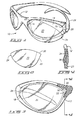
- Figure 1 is a perspective view of an article of eyewear in accordance with a preferred embodiment of the present invention, showing the left lens in a partially mounted position,
- Figure 2 is a front view of a lens from the eyewear of Figure 1.
- Figure 3 is a partially cut-away, front view of the eyewear of Figure 1.
- Figure 4 is a cross-sectional view taken along line 4-4 in Figure 3.
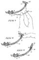
- Figure 5 is a side view of a portion of the eyewear of Figure 1.
- Figure 6 is a partially cutaway view of Figure 5.
- Figure 7 is a top cross-sectional view of a portion of the eyewear of Figure 1, showing the lens only partially mounted (the lens is not shown in cross-section).
- Figure 8 is a top cross-sectional view of a portion of the eyewear of Figure 1, showing the lens mounted with the pivot member in the closed, or unlocked, position (the lens is not shown in cross-section).
- Figure 9 is a top cross-sectional view of a portion of the eyewear of Figure 1, showing the lens mounted and the pivot member in the locked position (the lens is not shown in cross-section).
- Figure 10 is a top view of an article of eyewear in accordance with an alternative embodiment of the present invention.
- the eyewear 10 includes a frame 12 that defines two lens openings 14. Each lens opening 14 has a medial lens receiving recess 16 and a lateral lens receiving recess 18. A lens 20 can be removably mounted within each lens opening 14. Each lens 20 (the right hand lens is illustrated separately in Figure 2) has a medial tab portion 22 and a lateral tab portion 24. To mount the lens, the medial tab potion 22 is placed into the medial recess 16 and the lateral tab portion 24 is placed within the lateral recess 18. In this manner, each lens is held in position by reason of the engagement between the tab portions on the lenses and the corresponding recesses on the frame. The lenses may be removed and changed, by reversing the process. This allows a wide variety of lenses to be selectively mounted to a single article of eyewear and greatly increases the functionality and versatility of that eyewear.
- the illustrated embodiment also provides a positive manner of securely locking each lens in the mounted position. This is accomplished by means of a pivot member 26, having a locking tab 28, associated with each lens opening 14. As illustrated in Figure 1, the pivot members 18 are attached to the frame 12 and are moveable between a closed position and a locked position. In Figure 1, only the right-hand pivot member is shown in the locked position. (Unless noted otherwise, references to right-hand and left-hand sides are from the perspective of a wearer of the illustrated eyewear.) In the locked position, the locking tab 28 engages the lateral tab portion 24 to securely hold the lens in the mounted position.
- the illustrated frame 12, seen best in Figures 1 and 3, can be of virtually any desired shape and configuration.
- the lens openings 14 may also have a variety of shapes to accommodate a variety of lens shapes.
- the frame 12 completely encloses each lens opening.
- the lens opening need not be completely enclosed.
- the bottom of the lens opening may be open.
- the frame defines two lens receiving recesses for each lens opening-one on the medial side of the lens opening and one on the lateral side of the lens opening. Having the recesses on generally opposing sides of the lens opening provides for a more secure mounting of the lens to the frame.
- having a recess on the lateral side of the lens opening facilitates the illustrated locking mechanism and allows the pivot member to serve as an ear piece.
- the recesses need not be directly opposite from one another and can be located in many places about the periphery of the lens opening. For example, one recess could be positioned on the top of the lens opening and the other on the bottom or even on one side.
- Each lens receiving recess is shaped to receive the corresponding tab formed on the lens.
- the medial tab portion 22 comes to a slightly rounded point 30, seen best in Figure 2. As seen in Figure 3, this point 30 is received within the medial recess 22.
- the upper and lower boundaries of the recess serve to limit up and down motion of the point within the recess.
- the rear wall 32 and front wall 34 sandwich the point 30 and limit forward or backward movement of the tab within the recess.
- the recess is also provided with a cavity (seen best in Figures 7-9) which allows the point to pivot somewhat within the recess. As explained in more detail below, this pivoting facilitates the mounting and removal of the lens from the frame.
- the lateral tab portion 24 is received within the lateral recess 18 in a similar manner, illustrated best in Figures 5, 6 and 9.
- a gap 38 is provided in the front wall of the lateral recess 18. (The gap is seen best in Figure 1.)
- This gap cooperates with the pivot member to positively lock the lens firmly in position and also facilitates easy removal of the lens from the frame.
- the locking tab 28 fits within the gap 38 and engages the front face of the lens as shown in Figures 5, 6 and 9 to securely maintain the lens in position.
- the lateral recess is also provided with a finger groove 40 which allows a wearer's finger or fingernail to engage the lateral tab portion to insert or remove the lens. In the illustrated embodiment, the finger groove is accessible only when the pivot member is not in the locked position.
- the pivot member is hinged to the frame and the end opposite the locking tab 28 extends generally rearward to engage the head of a wearer.
- the illustrated pivot member also serves as an ear piece for the eyewear. While this design is particularly advantageous and efficient, in other embodiment, the pivot member may be separate from the ear piece and may pivot in a different manner.
- FIGs 7-9 The process of mounting a lens is illustrated in Figures 7-9.
- a wearer grasps the lens 20 firmly by the upper and lower edges and inserts the medial tab portion 22 into the medial recess 16.
- the cavity 36 accommodates the point 30 while the lens is in this pivoted position.
- the wearer pivots the lens toward the frame and, by placing a finger or fingernail on the end of the lateral tab portion 24, places the lateral tab portion 24 within the lateral recess 18, as shown in Figure 8.
- the gap 38 and the finger groove 40 accommodate the wearer's finger during this step of the mounting procedure.
- the front wall of the lateral recess slightly overhangs the lateral tab both above and below the gap.
- the lens is maintained in this position by the engagement of this overhang 42 with the lateral tab portion.
- a slight amount of pressure on the end of the lateral tab portion is applied. This pressure causes the lens, the frame, or both to flex slightly so that the tab can be placed under the overhang.
- the pressure is released, the flexed lens, frame or both return to normal so that the overhang engages the lateral tab portion.
- the lens can be locked firmly in place by pivoting the pivot member 26 to the locked position, shown in Figures 5, 6 and 9.
- the locking tab 28 overlaps with the lateral tab portion 22 sufficiently to hold the lens securely in place.
- the lens can be simply and quickly removed by reversing these steps: pivot the pivot member out of the locked position; engage the end of the lateral tab portion with a finger or fingernail; apply pressure to flex the lens, frame or both; pivot the lateral side of the lens outward from the frame; grasp the upper and lower edges of the lens securely; and withdraw the medial tab portion from the medial recess.
- the mounting and removal of a lens is simple and fast. Moreover, it can be accomplished without the need to touch the faces of the lens. This serves to allow a wearer the advantages of removable lenses and while reducing the possibility of damage to the lenses.
- the remainder of the lens may float forwardly of the frame, as seen in the alternative embodiment illustrated in Figure 10, to create a space 44 between the lens and the frame. This space increases the flow of air around the lens and helps to reduce fogging.
- the lenses are made of polycarbonate, and the frames are made of nylon. These materials provide the necessary flex to allow easy mounting and removal of the lens.
- the frames are made of nylon. These materials provide the necessary flex to allow easy mounting and removal of the lens.
- a number of other materials-such as glass, CR 39 or any other suitable non-opaque material for the lenses, or plastic or metal for the frames-could also be used and still provide the desired flex.
- the pivot member is made of the same material as the frame. Again, however, those skilled in the art will recognize that a wide variety of materials, either alone or in combination may be used in the described eyewear.
- an alternative embodiment might have a single lens which extends from the left lateral side, completely across a wearer's face, to the right lateral side.
- the use of recesses and cooperating tab portions, as shown above, could be readily adapted to allow such a lens to be quickly and easily mounted and removed.
- each illustrated lens has only two tab portions, in alternative embodiments it may be desirable to use more than two sets of cooperative recesses and tab portions per lens.
Landscapes
- Physics & Mathematics (AREA)
- Health & Medical Sciences (AREA)
- General Physics & Mathematics (AREA)
- Ophthalmology & Optometry (AREA)
- Optics & Photonics (AREA)
- Eyeglasses (AREA)
Abstract
Description
- The present invention relates to eyewear, and more particularly to eyewear having lenses that are quickly and easily removable and to a method of removably mounting lenses in eyewear.
- Eyewear is commonly worn for a variety of reasons. As a result, a variety of eyewear types, each specifically designed and intended for a particular use or a particular environment has been developed. For example, sunglasses are often worn to protect a wearer's eyes from undesirably bright direct sun light. In such an environment, the undesirable light typically comes from above the user. Sunglasses also may be worn for protection in environments, such as around snow or water, where an uncomfortable amount of glare is present. In the instance of glare, the undesirable light often comes from below the user. For this reason, a lens having characteristics that are well suited for protecting a wearer's eyes from direct sun light, may be less effective at protecting a wearer's eyes from glare. As a result, a variety of eyewear lenses, having different characteristics and providing different advantages, have been developed. To gain the advantages of various types of lenses has in the past, required a wearer to have multiple articles of eyewear-each having lenses of one of the various types.
- Eyewear is also worn as a fashion accessory. For many wearers the color or tint of the eyewear may be an important factor in determining the suitability of the eyewear as an accessory. Moreover, the desired color or tint may vary depending on the circumstances and the items with which the wearer desires to coordinate. Again, wearers, in the past, were required to have different articles of eyewear in order to provide a selection of lenses having different colors or tints to coordinate with different fashions.
- Accordingly, it would be advantageous if the lenses in an article of eyewear could be changed to allow the same eyewear to be used in different situations. For interchangeable lenses to be widely accepted, users must be able to remove and replace lenses quickly and easily.
- However, eyewear lenses are typically mounted in a manner that prevents them from being quickly and easily removed from the frame. For example, in one type of eyewear, the portion of the frame that defines the lens opening is provided with a small gap. The gap is spanned by a threaded screw which can be tightened to decrease the size of the gap and, hence, the size of the lens opening. The lens is positioned within the lens opening and the screw is lightened to clamp the lens within the opening. In eyewear of this type, removal of the lens requires tools and is not typically performed by the wearer. Typically, removal also requires direct contact with the from and rear faces of the lens and, as a result, may scratch, dirty or mar the lens.
- In some eyewear, the internal perimeter of the lens opening is provided with a groove into which the edge of the lens is engaged In some eyewear of this type, the edge of the lens is received within the groove. Alternatively, the perimeter of the lens may have a raised rib which is received within the groove. Again, however, in this type of eyewear the lenses are not intended to be removed by a user.
- In other eyewear, the frame is provided with a metal rim so that lenses having magnets about their periphery may be removably attached. Although this system allows a wearer to remove and interchange lenses, the presence of magnets on the lens may detract from the quality and appearance of the lens. Such a system also does not provide a sure mechanical connection of the lens to the frame. Moreover, such a system is not designed to reduce the possibility of a wearer handling the faces of the lens during the process of removing or interchanging the lenses. This increases the possibility of the front and rear faces of the lens being dirtied or damaged.
- Clip-on lens covers are also available for eyewear. Such covers often include a tinted lens cover and are suited to be clipped onto prescription eyewear to convert them into prescription sunglasses. In many cases, the clip-on lens cover can be flipped up so that the wearer looks through the untinted prescription lenses or, alternatively, flipped down so that the wearer looks through both the prescription lenses and the tinted lens covers.
- Accordingly, it is an object of the invention to provide eyewear having lenses that arc securely held in place within an item of eyewear, but which can be easily and quickly removed by a wearer.
- It is a further object of the invention to provide a method for removing and removably mounting lenses to the frame with minimal need to handle or touch the faces of the lenses.
- In accordance with these and other objects of the invention, eyewear in accordance with a preferred embodiment of the present invention has a frame which defines a least one opening. A first lens receiving recess is on one side of the opening and a second lens receiving recess is on a second side of the opening. A lens is provided that has a first tab portion and a second tab portion. The first tab portion is removably received within the first recess and the second tab portion is removably received within the second recess to removably hold the lens in position. In the illustrated embodiment, the first and second tab portions are integrally formed as part of the overall lens shape. However, this need not be the case.
- In one aspect of the invention, a pivot member is attached to the frame. The pivot member can be moved into a position in which it firmly locks the lens in place. In a preferred embodiment, the pivot member is provided with a locking tab and the second lens receiving recess is provided with a cooperating gap. In this manner, the locking tab is received within the gap and engages the second tab portion to lock the lens in place. In certain embodiments, when the pivot member is not in the locking position, the gap also allows access to the second tab portion to facilitate the easy mounting and removal of the lens. In particular, a groove may be provided to allow a wearer to insert a finger or fingernail under the second tab portion to easily remove the lens.
- In another aspect of the invention, the only portions of the lens to engage the frame are the first tab portion and the second tab portion. The remainder of the lens may be spaced from the frame to facilitate, for example, air circulation around the lens to reduce fogging.
- A lens in accordance with certain aspects of this invention is removably mounted to the frame by placing the first tab portion into the first lens receiving recess and placing the second tab portion into the second lens receiving recess. The pivot member can then be moved to the locking position to secure the lens in position. To remove the lens, the pivot member is moved out of the locking position, the second tab portion is removed from the second lens receiving recess and the first tab portion is removed from the first lens receiving recess. In the illustrated embodiment, both the mounting and removal of the lens can be done by holding only the edges and tab portions of the lens. Thus, the likelihood of damaging or scratching the faces of the lens is reduced.
- Other objects and aspects of the invention will become apparent to those skilled in the art from the detailed description of the preferred embodiment which is presented by way of example and not a limitation of the present invention.
- Figure 1 is a perspective view of an article of eyewear in accordance with a preferred embodiment of the present invention, showing the left lens in a partially mounted position,
- Figure 2 is a front view of a lens from the eyewear of Figure 1.
- Figure 3 is a partially cut-away, front view of the eyewear of Figure 1.
- Figure 4 is a cross-sectional view taken along line 4-4 in Figure 3.
- Figure 5 is a side view of a portion of the eyewear of Figure 1.
- Figure 6 is a partially cutaway view of Figure 5.
- Figure 7 is a top cross-sectional view of a portion of the eyewear of Figure 1, showing the lens only partially mounted (the lens is not shown in cross-section).
- Figure 8 is a top cross-sectional view of a portion of the eyewear of Figure 1, showing the lens mounted with the pivot member in the closed, or unlocked, position (the lens is not shown in cross-section).
- Figure 9 is a top cross-sectional view of a portion of the eyewear of Figure 1, showing the lens mounted and the pivot member in the locked position (the lens is not shown in cross-section).
- Figure 10 is a top view of an article of eyewear in accordance with an alternative embodiment of the present invention.
- An article of
eyewear 10 in accordance with a preferred embodiment of the present invention is shown in Figure 1. Theeyewear 10 includes aframe 12 that defines twolens openings 14. Eachlens opening 14 has a mediallens receiving recess 16 and a laterallens receiving recess 18. Alens 20 can be removably mounted within eachlens opening 14. Each lens 20 (the right hand lens is illustrated separately in Figure 2) has amedial tab portion 22 and alateral tab portion 24. To mount the lens, themedial tab potion 22 is placed into themedial recess 16 and thelateral tab portion 24 is placed within thelateral recess 18. In this manner, each lens is held in position by reason of the engagement between the tab portions on the lenses and the corresponding recesses on the frame. The lenses may be removed and changed, by reversing the process. This allows a wide variety of lenses to be selectively mounted to a single article of eyewear and greatly increases the functionality and versatility of that eyewear. - The illustrated embodiment also provides a positive manner of securely locking each lens in the mounted position. This is accomplished by means of a
pivot member 26, having a lockingtab 28, associated with eachlens opening 14. As illustrated in Figure 1, thepivot members 18 are attached to theframe 12 and are moveable between a closed position and a locked position. In Figure 1, only the right-hand pivot member is shown in the locked position. (Unless noted otherwise, references to right-hand and left-hand sides are from the perspective of a wearer of the illustrated eyewear.) In the locked position, thelocking tab 28 engages thelateral tab portion 24 to securely hold the lens in the mounted position. - The illustrated
frame 12, seen best in Figures 1 and 3, can be of virtually any desired shape and configuration. Similarly, thelens openings 14 may also have a variety of shapes to accommodate a variety of lens shapes. In the illustrated embodiment, theframe 12 completely encloses each lens opening. However, it should be understood that the lens opening need not be completely enclosed. For example, the bottom of the lens opening may be open. In the illustrated embodiment, the frame defines two lens receiving recesses for each lens opening-one on the medial side of the lens opening and one on the lateral side of the lens opening. Having the recesses on generally opposing sides of the lens opening provides for a more secure mounting of the lens to the frame. Similarly, having a recess on the lateral side of the lens opening facilitates the illustrated locking mechanism and allows the pivot member to serve as an ear piece. However, the recesses need not be directly opposite from one another and can be located in many places about the periphery of the lens opening. For example, one recess could be positioned on the top of the lens opening and the other on the bottom or even on one side. - Each lens receiving recess is shaped to receive the corresponding tab formed on the lens. In the illustrated embodiment, the
medial tab portion 22 comes to a slightlyrounded point 30, seen best in Figure 2. As seen in Figure 3, thispoint 30 is received within themedial recess 22. The upper and lower boundaries of the recess serve to limit up and down motion of the point within the recess. Similarly, the rear wall 32 and front wall 34 (seen best in Figure 4) sandwich thepoint 30 and limit forward or backward movement of the tab within the recess. The recess is also provided with a cavity (seen best in Figures 7-9) which allows the point to pivot somewhat within the recess. As explained in more detail below, this pivoting facilitates the mounting and removal of the lens from the frame. - The
lateral tab portion 24 is received within thelateral recess 18 in a similar manner, illustrated best in Figures 5, 6 and 9. In the illustrated embodiment, however, agap 38 is provided in the front wall of thelateral recess 18. (The gap is seen best in Figure 1.) This gap cooperates with the pivot member to positively lock the lens firmly in position and also facilitates easy removal of the lens from the frame. In particular, thelocking tab 28 fits within thegap 38 and engages the front face of the lens as shown in Figures 5, 6 and 9 to securely maintain the lens in position. The lateral recess is also provided with afinger groove 40 which allows a wearer's finger or fingernail to engage the lateral tab portion to insert or remove the lens. In the illustrated embodiment, the finger groove is accessible only when the pivot member is not in the locked position. - In the illustrated embodiment, the pivot member is hinged to the frame and the end opposite the
locking tab 28 extends generally rearward to engage the head of a wearer. In this manner, the illustrated pivot member also serves as an ear piece for the eyewear. While this design is particularly advantageous and efficient, in other embodiment, the pivot member may be separate from the ear piece and may pivot in a different manner. - The process of mounting a lens is illustrated in Figures 7-9. Initially, a wearer grasps the
lens 20 firmly by the upper and lower edges and inserts themedial tab portion 22 into themedial recess 16. As shown in Figure 7, thecavity 36 accommodates thepoint 30 while the lens is in this pivoted position. Still holding only the edges of the lens, the wearer pivots the lens toward the frame and, by placing a finger or fingernail on the end of thelateral tab portion 24, places thelateral tab portion 24 within thelateral recess 18, as shown in Figure 8. Thegap 38 and thefinger groove 40 accommodate the wearer's finger during this step of the mounting procedure. As seen best in Figure 6, the front wall of the lateral recess slightly overhangs the lateral tab both above and below the gap. The lens is maintained in this position by the engagement of thisoverhang 42 with the lateral tab portion. In order to insert the lateral tab portion under the overhang, a slight amount of pressure on the end of the lateral tab portion is applied. This pressure causes the lens, the frame, or both to flex slightly so that the tab can be placed under the overhang. When the pressure is released, the flexed lens, frame or both return to normal so that the overhang engages the lateral tab portion. - Once in the mounted position, shown in Figure 8, the lens can be locked firmly in place by pivoting the
pivot member 26 to the locked position, shown in Figures 5, 6 and 9. In the locked position, thelocking tab 28 overlaps with thelateral tab portion 22 sufficiently to hold the lens securely in place. - The lens can be simply and quickly removed by reversing these steps: pivot the pivot member out of the locked position; engage the end of the lateral tab portion with a finger or fingernail; apply pressure to flex the lens, frame or both; pivot the lateral side of the lens outward from the frame; grasp the upper and lower edges of the lens securely; and withdraw the medial tab portion from the medial recess.
- As can be appreciated from this description, the mounting and removal of a lens is simple and fast. Moreover, it can be accomplished without the need to touch the faces of the lens. This serves to allow a wearer the advantages of removable lenses and while reducing the possibility of damage to the lenses.
- From the foregoing, it is clear that the engagement of the medial tab portion with the medial recess and the lateral tab portion with the lateral recess are sufficient to hold the lens in position, particularly with the pivot member in the locking position. As a result, there is no need for any other portions of the lens to engage the frame. Nonetheless, in the embodiment illustrated in Figure 1-9, the entire lens fits within the lens opening and may be in contact with the frame. This allows the front face of the lens to be flush with the front of the frame to create a smooth, sleek appearance. However, since the engagement of the tab portions with the recesses is sufficient to hold the lens in place, the remainder of the lens may float forwardly of the frame, as seen in the alternative embodiment illustrated in Figure 10, to create a
space 44 between the lens and the frame. This space increases the flow of air around the lens and helps to reduce fogging. - It should also be appreciated that this invention can be implemented using a wide variety of shapes and materials. In the illustrated embodiment. the lenses are made of polycarbonate, and the frames are made of nylon. These materials provide the necessary flex to allow easy mounting and removal of the lens. However, those skilled in the art will recognize that a number of other materials-such as glass, CR 39 or any other suitable non-opaque material for the lenses, or plastic or metal for the frames-could also be used and still provide the desired flex. Further, it is not necessary that both the lens and the frame flex. Rather, so long as one or the other flex sufficiently to allow the mounting and removal of the lens, the advantages of the described eyewear are obtained. In the illustrated embodiment, the pivot member is made of the same material as the frame. Again, however, those skilled in the art will recognize that a wide variety of materials, either alone or in combination may be used in the described eyewear.
- Although only eyewear having two lens openings and two lenses is shown and described above, an alternative embodiment might have a single lens which extends from the left lateral side, completely across a wearer's face, to the right lateral side. The use of recesses and cooperating tab portions, as shown above, could be readily adapted to allow such a lens to be quickly and easily mounted and removed. Moreover, although each illustrated lens has only two tab portions, in alternative embodiments it may be desirable to use more than two sets of cooperative recesses and tab portions per lens.
- This detailed description is set forth only for purposes of illustrating examples of the present invention and should not be considered to limit the scope thereof in any way. Clearly, numerous additions, substitutions, and other modifications can be made to the invention without departing from the scope of the invention which is defined in the appended claims and equivalents thereof.
Claims (20)
- Eyewear comprising:a frame defining at least one opening, the frame having a first lens receiving recess on a first side of the opening and a second lens receiving recess on a second side of the opening; anda lens having a front face, a back face, a first tab portion and a second tab portion, the first tab portion positioned to be removably received within the first lens receiving recess and the second tab portion positioned to be removably received within the second lens receiving recess to removably hold the lens in position.
- The eyewear of claim 1 in which the second lens receiving recess is provided with a gap, the gap allowing access to the second tab portion to facilitate mounting and removal of the lens.
- The eyewear of claim 1 further comprising:
a pivot member having a locking tab, the pivot member being movable between a first position and a locked position in which the locking tab cooperates with the second recess to lock the lens in position. - The eyewear of claim 2 further comprising:
a pivot member having a locking tab, the pivot member being movable between a first position and a locked position in which the locking tab is positioned within the gap to lock the lens in position. - The eyewear of claim 4 in which the gap is further provided with a groove for providing access to the second tab portion.
- The eyewear of claim 4 in which the lens engages the frame only at the first tab portion and the second tab portion.
- The eyewear of claim 6 in which the back face of the lens is spaced forwardly from the frame except at the first tab portion and the second tab portion.
- The eyewear of claim 4 in which the frame encloses the opening.
- The eyewear of claim 4 in which the pivot member is hingedly connected to the frame.
- The eyewear of claim 9 in which the pivot member comprises an ear piece to engage the head of a wearer when in the locked position.
- Eyewear comprising:a frame defining at least one opening, the opening having a first lens receiving recess on a first portion of the opening and a second lens receiving recess on the second portion of the opening, the first portion being located on an opposing side of the opening from the second portion, the second lens receiving opening having a gap;a lens having a front face, a back face, a first tab portion and a second tab portion, the first tab portion positioned to removably fit within the first lens receiving recess and the second tab portion positioned to removably fit within the second lens receiving recess to removably hold the lens in position;a pivot member hingedly attached to the frame and movable between a first position and a locked position, the pivot member having a locking tab which fits within the gap and engages the second tab portion to lock lens in position when the pivot member is in the locked position, the pivot member also adapted to engage the head of a wearer when in the locked position.
- The eyewear of claim 11 in which the pivot member comprises an ear piece.
- The eyewear of claim 11 in which the gap is further provided with a groove for providing access to the second tab portion.
- The eyewear of claim 11 in which the lens engages the frame only at the first tab portion and the second tab portion.
- The eyewear of claim 14 in which the back face of the lens is spaced forwardly from the frame except at the first tab portion and the second tab portion.
- A method of removably mounting an eyewear lens, comprising the steps of:providing a frame defining at least one opening, the opening having a first lens receiving recess on a first portion of the opening and a second lens receiving recess on the second portion of the opening:providing a lens having a front face, a back face, a first tab portion and a second tab portion;placing the first tab portion within the first lens receiving opening; andplacing the second tab portion with the second lens receiving opening.
- The method of claim 16 further comprising the steps of:providing a pivot member attached to the frame and having a locking tab, the pivot member being movable between a first position and a locked position in which the locking tab engages the lens to lock it in position; andmoving the pivot member to the locked position.
- The method of claim 17 in which the second lens receiving recess has a gap and the locking tab fits within the gap and engages the second tab portion when in the locked position.
- The method of claim 18 in which the lens engages the frame only at the first tab portion and the second tab portion.
- The eyewear of claim 19 in which the back face of the lens is spaced forwardly from the frame except at the first tab portion and the second tab portion.
Priority Applications (1)
| Application Number | Priority Date | Filing Date | Title |
|---|---|---|---|
| DE20023683U DE20023683U1 (en) | 1999-03-03 | 2000-03-02 | Eyewear with removable lenses and method of removably mounting lenses in eyewear |
Applications Claiming Priority (2)
| Application Number | Priority Date | Filing Date | Title |
|---|---|---|---|
| US09/261,917 US6086199A (en) | 1999-03-03 | 1999-03-03 | Eyewear with removable lenses and method of removably mounting lenses in eyewear |
| US261917 | 1999-03-03 |
Publications (2)
| Publication Number | Publication Date |
|---|---|
| EP1033602A1 true EP1033602A1 (en) | 2000-09-06 |
| EP1033602B1 EP1033602B1 (en) | 2006-05-10 |
Family
ID=22995448
Family Applications (1)
| Application Number | Title | Priority Date | Filing Date |
|---|---|---|---|
| EP00301701A Expired - Lifetime EP1033602B1 (en) | 1999-03-03 | 2000-03-02 | Eyewear with removable lenses and method of removably mounting lenses in eyewear |
Country Status (5)
| Country | Link |
|---|---|
| US (1) | US6086199A (en) |
| EP (1) | EP1033602B1 (en) |
| AT (1) | ATE326023T1 (en) |
| DE (1) | DE60027810T2 (en) |
| ES (1) | ES2259979T3 (en) |
Cited By (1)
| Publication number | Priority date | Publication date | Assignee | Title |
|---|---|---|---|---|
| DE102004035592A1 (en) * | 2004-07-22 | 2006-03-16 | Nigura Optik Gmbh | Spectacles e.g. sports glass, has lenses that are insertable into convexity of groove of frame by expansion connection in recess of seat bridge, where lateral contact surfaces of recess have bevels for force-fit retention of lenses |
Families Citing this family (63)
| Publication number | Priority date | Publication date | Assignee | Title |
|---|---|---|---|---|
| TW387561U (en) * | 1999-09-01 | 2000-04-11 | Bo Shown Spectacles Ind Co Ltd | Eyeglasses having easily exchangeable lens |
| US6224209B1 (en) * | 2000-04-25 | 2001-05-01 | Wu Meihua Chen | Eyeglasses frame allowing replacement of lenses |
| FR2815727B1 (en) * | 2000-10-25 | 2003-03-07 | Lebas Sports | PAIR OF INTERCHANGEABLE LENSES |
| ITTO20010413A1 (en) * | 2001-05-03 | 2002-11-03 | Nico S R L | GLASSES WITH INTERCHANGEABLE LENSES. |
| FR2825159B1 (en) * | 2001-05-28 | 2003-09-26 | Bab Sports S A | GLASSES WITH INTERCHANGEABLE EYEWEAR |
| FR2830945A1 (en) * | 2001-10-11 | 2003-04-18 | Owoay | Spectacle lens and frame assembly has inner surfaces of lens outer edges stepped to form tongues engaging with matching grooves in frame members |
| FR2830944A1 (en) * | 2001-10-11 | 2003-04-18 | Owoay | Spectacle lens and frame assembly has inner surfaces of lens outer edges stepped to form tongues engaging with matching grooves in frame members |
| EP1451632A1 (en) * | 2001-07-24 | 2004-09-01 | Owoay | Spectacle lens and pair of spectacles comprising two such lenses |
| US6592220B1 (en) | 2002-01-30 | 2003-07-15 | Lak Cheong | Eyeglass frame with removably mounted lenses |
| US6712465B1 (en) * | 2003-04-30 | 2004-03-30 | Irene Corporation | Eyeglasses having additional, replaceable lenses |
| WO2005019902A2 (en) * | 2003-08-14 | 2005-03-03 | Bacou-Dalloz Eye & Face Protection, Inc. | Safety glasses with pivoting interchangeable single-lens |
| US6971745B2 (en) * | 2003-10-03 | 2005-12-06 | Brent Sheldon | Eyewear having lenses with rims |
| US7399078B2 (en) * | 2003-10-03 | 2008-07-15 | Brent Sheldon | Attachment of prescription lenses to eyewear having wrap-type frames |
| US20050073643A1 (en) * | 2003-10-03 | 2005-04-07 | Brent Sheldon | Eyewear having lenses with RIMS |
| US6863395B1 (en) | 2003-12-29 | 2005-03-08 | Irene Corporation | Eyeglasses having detachable lenses |
| DE102004059023A1 (en) * | 2004-12-08 | 2006-06-29 | Uvex Arbeitsschutz Gmbh | Glasses, in particular safety goggles |
| USD542330S1 (en) | 2005-02-25 | 2007-05-08 | Fatheadz, Inc. | Sunglasses |
| USD554176S1 (en) | 2005-06-24 | 2007-10-30 | Fatheadz, Inc. | Wired sunglasses |
| USD556241S1 (en) | 2005-11-04 | 2007-11-27 | Fatheadz, Inc. | Sunglasses |
| USD556243S1 (en) | 2005-11-04 | 2007-11-27 | Fatheadz, Inc. | Sunglasses |
| USD554688S1 (en) | 2005-11-04 | 2007-11-06 | Fatheadz, Inc. | Sunglasses |
| USD559301S1 (en) | 2005-11-04 | 2008-01-08 | Fatheadz, Inc. | Sunglasses |
| USD556817S1 (en) | 2005-11-04 | 2007-12-04 | Fatheadz, Inc. | Sunglasses |
| USD570898S1 (en) | 2005-11-04 | 2008-06-10 | Fatheadz, Inc. | Sunglasses |
| USD556248S1 (en) | 2005-11-04 | 2007-11-27 | Fatheadz, Inc. | Sunglasses |
| USD556242S1 (en) | 2005-11-04 | 2007-11-27 | Fatheadz, Inc. | Sunglasses |
| US7452068B2 (en) * | 2005-11-14 | 2008-11-18 | Nike, Inc. | Eyewear with clip-on frame and lens |
| US7325919B2 (en) * | 2005-12-13 | 2008-02-05 | Neville Sheldon | Eyewear having lens retaining member |
| US7797765B2 (en) * | 2005-12-30 | 2010-09-21 | Bell Sports, Inc. | Lens replacement system |
| US7448749B2 (en) * | 2006-01-11 | 2008-11-11 | Nike, Inc. | Eyewear with temporal vent |
| US7461935B2 (en) | 2006-04-26 | 2008-12-09 | Nike, Inc. | Eyewear with inner and outer frame lens |
| US7219992B1 (en) * | 2006-07-05 | 2007-05-22 | Szu-Miao Wu | Eyeglasses |
| DE102006053944A1 (en) * | 2006-11-15 | 2008-05-29 | Rodenstock Gmbh | Spectacles-attachment-combination, has fixing element designed such that fixing element fixes/separates fastening element at/from spectacles in open position and retracted/hinged position of pivotable arms, respectively |
| US7497569B2 (en) * | 2006-12-06 | 2009-03-03 | Bell Sports, Inc. | Partially entrapped frame having a removable lens |
| US7524055B2 (en) * | 2007-03-19 | 2009-04-28 | Nike, Inc. | Eyewear with lens and interlocking nosepiece and frame |
| US7553013B2 (en) * | 2007-09-21 | 2009-06-30 | York Tsai | Eyeglasses having quick lens release feature |
| JP5676439B2 (en) | 2008-07-03 | 2015-02-25 | オークリー インコーポレイテッド | Floating lens mounting system |
| US8469510B2 (en) | 2009-01-09 | 2013-06-25 | Oakley, Inc. | Eyewear with enhanced ballistic resistance |
| US8192015B2 (en) | 2009-01-09 | 2012-06-05 | Oakley, Inc. | Eyeglass with enhanced ballistic resistance |
| US8201939B2 (en) * | 2009-07-30 | 2012-06-19 | Nike, Inc. | Eyewear with frame and rear plate |
| US7931365B2 (en) * | 2009-08-04 | 2011-04-26 | Jay-Y Enterprise Co., Inc. | Replaceable-lens eyewear and kit |
| US7887181B1 (en) * | 2009-11-15 | 2011-02-15 | Chun-Nan Chen | Eyeglass structure with detachable viewing lens |
| EP2893911B1 (en) | 2010-03-19 | 2018-06-06 | Oakley, Inc. | Eyewear |
| AU2011289179A1 (en) | 2010-08-13 | 2013-03-14 | Oakley, Inc. | Eyewear with lens retention mechanism |
| US8182086B2 (en) * | 2010-09-20 | 2012-05-22 | Lak Cheong | Eyeglass frame, eyewear, and an eyewear assembly method |
| US9188792B2 (en) | 2011-09-22 | 2015-11-17 | Oakley, Inc. | Mounting mechanism for eyewear |
| US9122078B2 (en) | 2011-12-01 | 2015-09-01 | Oakley, Inc. | Releasable earstem mounting mechanism for eyewear |
| US8876282B2 (en) | 2012-05-09 | 2014-11-04 | Jeffrey A. Taylor, Jr. | Eyewear system |
| EP2890341B1 (en) | 2012-08-31 | 2024-10-16 | Oakley, Inc. | Eyewear having removably attached eyewear attachment |
| US10357400B2 (en) | 2012-12-11 | 2019-07-23 | Oakley, Inc. | Eyewear with outriggers |
| WO2014138159A1 (en) | 2013-03-07 | 2014-09-12 | Oakley, Inc. | Regeneratable ant-fogging element for goggle |
| US8870368B1 (en) * | 2013-04-26 | 2014-10-28 | China-Star Worldwide Corp. | Eyeglasses with replaceable lenses |
| US9588355B2 (en) * | 2014-01-31 | 2017-03-07 | Steven COHN | Pair of glasses with secondary lenses |
| WO2015148770A1 (en) | 2014-03-27 | 2015-10-01 | Oakley, Inc. | Mounting mechanism for eyewear |
| WO2017062813A1 (en) | 2015-10-09 | 2017-04-13 | Oakley, Inc. | Headworn supports with passive venting and removable lens |
| US9709817B2 (en) | 2015-12-07 | 2017-07-18 | Oakley, Inc. | Eyewear retention devices and methods |
| JP2018538575A (en) | 2015-12-08 | 2018-12-27 | オークリー インコーポレイテッド | Eyewear traction device and method |
| US10359642B2 (en) | 2016-04-22 | 2019-07-23 | Oakley, Inc. | Mounting mechanism for eyewear |
| US10197814B2 (en) | 2017-03-03 | 2019-02-05 | Smith Optics, Inc. | Magnetic attachment mechanism for eyewear |
| USD849826S1 (en) | 2017-03-03 | 2019-05-28 | Smith Optics, Inc. | Eyerwear |
| US10444533B2 (en) | 2017-05-15 | 2019-10-15 | Revision Military Inc. | Eyewear with removable lenses |
| US11185965B2 (en) * | 2017-06-21 | 2021-11-30 | Bionic Thumb Tools Llc | Optician's tool and method for removing or inserting lenses |
| USD828438S1 (en) | 2017-09-04 | 2018-09-11 | Steven Rinehart | Eyewear |
Citations (5)
| Publication number | Priority date | Publication date | Assignee | Title |
|---|---|---|---|---|
| GB699837A (en) * | 1951-05-02 | 1953-11-18 | George Peter Kimmel | Improvements relating to opthalmic mountings |
| US2754724A (en) * | 1951-03-07 | 1956-07-17 | Fishman Samuel | Ophthalmic mounting |
| GB1017419A (en) * | 1962-11-06 | 1966-01-19 | Lunetiers Cottet Poichet Tagno | Improvements in or relating to spectacle lens mountings with metallic rims |
| US5418580A (en) * | 1994-05-05 | 1995-05-23 | Larry L. Sondrol | Interchangeable lens eyeglasses with pivoting temple release mechanism |
| US5760866A (en) * | 1996-08-07 | 1998-06-02 | David Wedeck | Eyeglass frame adapted to removal and insertion of lenses |
Family Cites Families (13)
| Publication number | Priority date | Publication date | Assignee | Title |
|---|---|---|---|---|
| US4187006A (en) * | 1978-07-26 | 1980-02-05 | Premier Athletic Products Corp. | Flip-down sunglasses |
| US4217037A (en) * | 1978-07-26 | 1980-08-12 | Lemelson Jerome H | Eyeglass shields |
| US4602856A (en) * | 1984-02-13 | 1986-07-29 | Marks Mortimer M | Combined photopic and scotopic viewers for two-dimensional moving image displays |
| US4715702A (en) * | 1986-10-20 | 1987-12-29 | Dillon Stephen M | Decorative lens |
| US5144344A (en) * | 1989-05-25 | 1992-09-01 | Sony Corporation | Spectacles for stereoscopic pictures |
| US5187502A (en) * | 1991-09-10 | 1993-02-16 | Howell Joe D | Pilot's visor |
| US5300963A (en) * | 1992-02-14 | 1994-04-05 | Kanda Optical Co., Ltd. | Structure for attaching member for protecting eyes from wind and dust |
| US5321442A (en) * | 1992-02-25 | 1994-06-14 | Albanese Gerry M | Eyeglasses with detachable lenses, sidebars, and adjustable earpieces |
| US5264875A (en) * | 1992-08-27 | 1993-11-23 | Cooper George F | Clip-on splash shield for eyeglasses |
| US5467148A (en) * | 1993-11-08 | 1995-11-14 | Bausch & Lomb Incorporated | Eyewear having interchangeable lenses |
| US5402189A (en) * | 1994-01-19 | 1995-03-28 | Gill; Vicki L. | Side shield for eyeglasses and method of making the same |
| US5602603A (en) * | 1995-12-22 | 1997-02-11 | Bondet; Pierre N. | Eyeglasses having interchangeable lenses and attachment clips |
| TW351459U (en) * | 1998-03-16 | 1999-01-21 | Shiou-Wen Chiou | Novel glasses with replaceable lens |
-
1999
- 1999-03-03 US US09/261,917 patent/US6086199A/en not_active Expired - Lifetime
-
2000
- 2000-03-02 EP EP00301701A patent/EP1033602B1/en not_active Expired - Lifetime
- 2000-03-02 ES ES00301701T patent/ES2259979T3/en not_active Expired - Lifetime
- 2000-03-02 AT AT00301701T patent/ATE326023T1/en not_active IP Right Cessation
- 2000-03-02 DE DE60027810T patent/DE60027810T2/en not_active Expired - Lifetime
Patent Citations (5)
| Publication number | Priority date | Publication date | Assignee | Title |
|---|---|---|---|---|
| US2754724A (en) * | 1951-03-07 | 1956-07-17 | Fishman Samuel | Ophthalmic mounting |
| GB699837A (en) * | 1951-05-02 | 1953-11-18 | George Peter Kimmel | Improvements relating to opthalmic mountings |
| GB1017419A (en) * | 1962-11-06 | 1966-01-19 | Lunetiers Cottet Poichet Tagno | Improvements in or relating to spectacle lens mountings with metallic rims |
| US5418580A (en) * | 1994-05-05 | 1995-05-23 | Larry L. Sondrol | Interchangeable lens eyeglasses with pivoting temple release mechanism |
| US5760866A (en) * | 1996-08-07 | 1998-06-02 | David Wedeck | Eyeglass frame adapted to removal and insertion of lenses |
Cited By (1)
| Publication number | Priority date | Publication date | Assignee | Title |
|---|---|---|---|---|
| DE102004035592A1 (en) * | 2004-07-22 | 2006-03-16 | Nigura Optik Gmbh | Spectacles e.g. sports glass, has lenses that are insertable into convexity of groove of frame by expansion connection in recess of seat bridge, where lateral contact surfaces of recess have bevels for force-fit retention of lenses |
Also Published As
| Publication number | Publication date |
|---|---|
| ATE326023T1 (en) | 2006-06-15 |
| ES2259979T3 (en) | 2006-11-01 |
| US6086199A (en) | 2000-07-11 |
| DE60027810D1 (en) | 2006-06-14 |
| EP1033602B1 (en) | 2006-05-10 |
| DE60027810T2 (en) | 2006-09-28 |
Similar Documents
| Publication | Publication Date | Title |
|---|---|---|
| US6086199A (en) | Eyewear with removable lenses and method of removably mounting lenses in eyewear | |
| USD349123S (en) | Spectacles having integral illumination | |
| CA1299817C (en) | Protective eyewear with removable nosepiece and corrective spectacle | |
| USD379263S (en) | Case for an eyeglass and contact lenses | |
| US10649237B2 (en) | Multi-functional glasses | |
| CA1118246A (en) | Sports spectacle structure | |
| US5614963A (en) | Sun shield system for protecting the eyes from UV and infrared components of sunlight | |
| USD280909S (en) | Spectacle frame | |
| US5528320A (en) | Protective eyewear | |
| US3884561A (en) | Lens holding groove means | |
| US20030223032A1 (en) | Eyewear and system | |
| USD406333S (en) | Center mount snorkel | |
| JP2628569B2 (en) | Detachable sunglasses with magnet | |
| US5048943A (en) | Eyewear with rearview mirror | |
| KR102498754B1 (en) | Eyewear with adjustable temples angle and detachable the temple | |
| USD353712S (en) | Combination spectacle case and contact lens vial | |
| US5539561A (en) | Eyeglass having removable temple/lens connector | |
| USD333037S (en) | Eyeglass case | |
| US5261582A (en) | Belt case for eyeglasses | |
| USD330561S (en) | Sunglasses lens frame | |
| US4666266A (en) | Eyeglasses having lens storage means | |
| USD403294S (en) | Holder for securing eyeglasses to a sunvisor | |
| KR102087621B1 (en) | Eyewear with detachable lens | |
| USD321356S (en) | Spectacle frames | |
| US6984036B1 (en) | Safety shield for eyewear assembly |
Legal Events
| Date | Code | Title | Description |
|---|---|---|---|
| PUAI | Public reference made under article 153(3) epc to a published international application that has entered the european phase |
Free format text: ORIGINAL CODE: 0009012 |
|
| AK | Designated contracting states |
Kind code of ref document: A1 Designated state(s): AT BE CH CY DE DK ES FI FR GB GR IE IT LI LU MC NL PT SE |
|
| AX | Request for extension of the european patent |
Free format text: AL;LT;LV;MK;RO;SI |
|
| 17P | Request for examination filed |
Effective date: 20010306 |
|
| AKX | Designation fees paid |
Free format text: AT BE CH CY DE DK ES FI FR GB GR IE IT LI LU MC NL PT SE |
|
| 17Q | First examination report despatched |
Effective date: 20040528 |
|
| GRAP | Despatch of communication of intention to grant a patent |
Free format text: ORIGINAL CODE: EPIDOSNIGR1 |
|
| GRAS | Grant fee paid |
Free format text: ORIGINAL CODE: EPIDOSNIGR3 |
|
| GRAA | (expected) grant |
Free format text: ORIGINAL CODE: 0009210 |
|
| AK | Designated contracting states |
Kind code of ref document: B1 Designated state(s): AT BE CH CY DE DK ES FI FR GB GR IE IT LI LU MC NL PT SE |
|
| PG25 | Lapsed in a contracting state [announced via postgrant information from national office to epo] |
Ref country code: IT Free format text: LAPSE BECAUSE OF FAILURE TO SUBMIT A TRANSLATION OF THE DESCRIPTION OR TO PAY THE FEE WITHIN THE PRESCRIBED TIME-LIMIT;WARNING: LAPSES OF ITALIAN PATENTS WITH EFFECTIVE DATE BEFORE 2007 MAY HAVE OCCURRED AT ANY TIME BEFORE 2007. THE CORRECT EFFECTIVE DATE MAY BE DIFFERENT FROM THE ONE RECORDED. Effective date: 20060510 Ref country code: CH Free format text: LAPSE BECAUSE OF FAILURE TO SUBMIT A TRANSLATION OF THE DESCRIPTION OR TO PAY THE FEE WITHIN THE PRESCRIBED TIME-LIMIT Effective date: 20060510 Ref country code: LI Free format text: LAPSE BECAUSE OF FAILURE TO SUBMIT A TRANSLATION OF THE DESCRIPTION OR TO PAY THE FEE WITHIN THE PRESCRIBED TIME-LIMIT Effective date: 20060510 Ref country code: NL Free format text: LAPSE BECAUSE OF FAILURE TO SUBMIT A TRANSLATION OF THE DESCRIPTION OR TO PAY THE FEE WITHIN THE PRESCRIBED TIME-LIMIT Effective date: 20060510 Ref country code: FI Free format text: LAPSE BECAUSE OF FAILURE TO SUBMIT A TRANSLATION OF THE DESCRIPTION OR TO PAY THE FEE WITHIN THE PRESCRIBED TIME-LIMIT Effective date: 20060510 Ref country code: BE Free format text: LAPSE BECAUSE OF FAILURE TO SUBMIT A TRANSLATION OF THE DESCRIPTION OR TO PAY THE FEE WITHIN THE PRESCRIBED TIME-LIMIT Effective date: 20060510 Ref country code: AT Free format text: LAPSE BECAUSE OF FAILURE TO SUBMIT A TRANSLATION OF THE DESCRIPTION OR TO PAY THE FEE WITHIN THE PRESCRIBED TIME-LIMIT Effective date: 20060510 |
|
| REG | Reference to a national code |
Ref country code: GB Ref legal event code: FG4D |
|
| REG | Reference to a national code |
Ref country code: CH Ref legal event code: EP |
|
| REF | Corresponds to: |
Ref document number: 60027810 Country of ref document: DE Date of ref document: 20060614 Kind code of ref document: P |
|
| REG | Reference to a national code |
Ref country code: IE Ref legal event code: FG4D |
|
| PG25 | Lapsed in a contracting state [announced via postgrant information from national office to epo] |
Ref country code: DK Free format text: LAPSE BECAUSE OF FAILURE TO SUBMIT A TRANSLATION OF THE DESCRIPTION OR TO PAY THE FEE WITHIN THE PRESCRIBED TIME-LIMIT Effective date: 20060810 Ref country code: SE Free format text: LAPSE BECAUSE OF FAILURE TO SUBMIT A TRANSLATION OF THE DESCRIPTION OR TO PAY THE FEE WITHIN THE PRESCRIBED TIME-LIMIT Effective date: 20060810 |
|
| PG25 | Lapsed in a contracting state [announced via postgrant information from national office to epo] |
Ref country code: PT Free format text: LAPSE BECAUSE OF FAILURE TO SUBMIT A TRANSLATION OF THE DESCRIPTION OR TO PAY THE FEE WITHIN THE PRESCRIBED TIME-LIMIT Effective date: 20061010 |
|
| ET | Fr: translation filed | ||
| NLV1 | Nl: lapsed or annulled due to failure to fulfill the requirements of art. 29p and 29m of the patents act | ||
| REG | Reference to a national code |
Ref country code: ES Ref legal event code: FG2A Ref document number: 2259979 Country of ref document: ES Kind code of ref document: T3 |
|
| REG | Reference to a national code |
Ref country code: CH Ref legal event code: PL |
|
| PLBE | No opposition filed within time limit |
Free format text: ORIGINAL CODE: 0009261 |
|
| STAA | Information on the status of an ep patent application or granted ep patent |
Free format text: STATUS: NO OPPOSITION FILED WITHIN TIME LIMIT |
|
| 26N | No opposition filed |
Effective date: 20070213 |
|
| PG25 | Lapsed in a contracting state [announced via postgrant information from national office to epo] |
Ref country code: IE Free format text: LAPSE BECAUSE OF NON-PAYMENT OF DUE FEES Effective date: 20070302 Ref country code: MC Free format text: LAPSE BECAUSE OF NON-PAYMENT OF DUE FEES Effective date: 20070331 |
|
| PG25 | Lapsed in a contracting state [announced via postgrant information from national office to epo] |
Ref country code: GR Free format text: LAPSE BECAUSE OF FAILURE TO SUBMIT A TRANSLATION OF THE DESCRIPTION OR TO PAY THE FEE WITHIN THE PRESCRIBED TIME-LIMIT Effective date: 20060811 |
|
| PG25 | Lapsed in a contracting state [announced via postgrant information from national office to epo] |
Ref country code: LU Free format text: LAPSE BECAUSE OF NON-PAYMENT OF DUE FEES Effective date: 20070302 Ref country code: CY Free format text: LAPSE BECAUSE OF FAILURE TO SUBMIT A TRANSLATION OF THE DESCRIPTION OR TO PAY THE FEE WITHIN THE PRESCRIBED TIME-LIMIT Effective date: 20060510 |
|
| REG | Reference to a national code |
Ref country code: GB Ref legal event code: 732E Free format text: REGISTERED BETWEEN 20140626 AND 20140702 |
|
| REG | Reference to a national code |
Ref country code: FR Ref legal event code: PLFP Year of fee payment: 16 |
|
| REG | Reference to a national code |
Ref country code: DE Ref legal event code: R082 Ref document number: 60027810 Country of ref document: DE Representative=s name: BOEHMERT & BOEHMERT ANWALTSPARTNERSCHAFT MBB -, DE |
|
| REG | Reference to a national code |
Ref country code: DE Ref legal event code: R082 Ref document number: 60027810 Country of ref document: DE Representative=s name: BOEHMERT & BOEHMERT ANWALTSPARTNERSCHAFT MBB -, DE Effective date: 20150401 Ref country code: DE Ref legal event code: R081 Ref document number: 60027810 Country of ref document: DE Owner name: NIKE INNOVATE C.V. (KOMMANDITGESELLSCHAFT NIED, US Free format text: FORMER OWNER: NIKE INTERNATIONAL LTD., BEAVERTON, OREG., US Effective date: 20150401 |
|
| REG | Reference to a national code |
Ref country code: FR Ref legal event code: TP Owner name: NIKE INNOVATE C.V., US Effective date: 20150420 |
|
| REG | Reference to a national code |
Ref country code: FR Ref legal event code: PLFP Year of fee payment: 17 |
|
| REG | Reference to a national code |
Ref country code: FR Ref legal event code: PLFP Year of fee payment: 18 |
|
| PGFP | Annual fee paid to national office [announced via postgrant information from national office to epo] |
Ref country code: DE Payment date: 20170221 Year of fee payment: 18 |
|
| REG | Reference to a national code |
Ref country code: FR Ref legal event code: PLFP Year of fee payment: 19 |
|
| REG | Reference to a national code |
Ref country code: DE Ref legal event code: R119 Ref document number: 60027810 Country of ref document: DE |
|
| PG25 | Lapsed in a contracting state [announced via postgrant information from national office to epo] |
Ref country code: DE Free format text: LAPSE BECAUSE OF NON-PAYMENT OF DUE FEES Effective date: 20181002 |
|
| PGFP | Annual fee paid to national office [announced via postgrant information from national office to epo] |
Ref country code: GB Payment date: 20190227 Year of fee payment: 20 Ref country code: FR Payment date: 20190111 Year of fee payment: 20 Ref country code: IT Payment date: 20190326 Year of fee payment: 20 |
|
| PGFP | Annual fee paid to national office [announced via postgrant information from national office to epo] |
Ref country code: ES Payment date: 20190401 Year of fee payment: 20 |
|
| REG | Reference to a national code |
Ref country code: GB Ref legal event code: PE20 Expiry date: 20200301 |
|
| PG25 | Lapsed in a contracting state [announced via postgrant information from national office to epo] |
Ref country code: GB Free format text: LAPSE BECAUSE OF EXPIRATION OF PROTECTION Effective date: 20200301 |
|
| REG | Reference to a national code |
Ref country code: ES Ref legal event code: FD2A Effective date: 20201201 |
|
| PG25 | Lapsed in a contracting state [announced via postgrant information from national office to epo] |
Ref country code: ES Free format text: LAPSE BECAUSE OF EXPIRATION OF PROTECTION Effective date: 20200303 |