EP1033543A2 - Slush producing process and device - Google Patents
Slush producing process and device Download PDFInfo
- Publication number
- EP1033543A2 EP1033543A2 EP00200756A EP00200756A EP1033543A2 EP 1033543 A2 EP1033543 A2 EP 1033543A2 EP 00200756 A EP00200756 A EP 00200756A EP 00200756 A EP00200756 A EP 00200756A EP 1033543 A2 EP1033543 A2 EP 1033543A2
- Authority
- EP
- European Patent Office
- Prior art keywords
- slush
- interior space
- collection portion
- liquid
- cooling process
- Prior art date
- Legal status (The legal status is an assumption and is not a legal conclusion. Google has not performed a legal analysis and makes no representation as to the accuracy of the status listed.)
- Granted
Links
Images
Classifications
-
- B—PERFORMING OPERATIONS; TRANSPORTING
- B64—AIRCRAFT; AVIATION; COSMONAUTICS
- B64G—COSMONAUTICS; VEHICLES OR EQUIPMENT THEREFOR
- B64G1/00—Cosmonautic vehicles
- B64G1/22—Parts of, or equipment specially adapted for fitting in or to, cosmonautic vehicles
- B64G1/40—Arrangements or adaptations of propulsion systems
- B64G1/402—Propellant tanks; Feeding propellants
-
- B—PERFORMING OPERATIONS; TRANSPORTING
- B64—AIRCRAFT; AVIATION; COSMONAUTICS
- B64G—COSMONAUTICS; VEHICLES OR EQUIPMENT THEREFOR
- B64G5/00—Ground equipment for vehicles, e.g. starting towers, fuelling arrangements
-
- C—CHEMISTRY; METALLURGY
- C06—EXPLOSIVES; MATCHES
- C06B—EXPLOSIVES OR THERMIC COMPOSITIONS; MANUFACTURE THEREOF; USE OF SINGLE SUBSTANCES AS EXPLOSIVES
- C06B47/00—Compositions in which the components are separately stored until the moment of burning or explosion, e.g. "Sprengel"-type explosives; Suspensions of solid component in a normally non-explosive liquid phase, including a thickened aqueous phase
- C06B47/02—Compositions in which the components are separately stored until the moment of burning or explosion, e.g. "Sprengel"-type explosives; Suspensions of solid component in a normally non-explosive liquid phase, including a thickened aqueous phase the components comprising a binary propellant
- C06B47/06—Compositions in which the components are separately stored until the moment of burning or explosion, e.g. "Sprengel"-type explosives; Suspensions of solid component in a normally non-explosive liquid phase, including a thickened aqueous phase the components comprising a binary propellant a component being a liquefied normally gaseous material supplying oxygen
-
- C—CHEMISTRY; METALLURGY
- C06—EXPLOSIVES; MATCHES
- C06B—EXPLOSIVES OR THERMIC COMPOSITIONS; MANUFACTURE THEREOF; USE OF SINGLE SUBSTANCES AS EXPLOSIVES
- C06B47/00—Compositions in which the components are separately stored until the moment of burning or explosion, e.g. "Sprengel"-type explosives; Suspensions of solid component in a normally non-explosive liquid phase, including a thickened aqueous phase
- C06B47/02—Compositions in which the components are separately stored until the moment of burning or explosion, e.g. "Sprengel"-type explosives; Suspensions of solid component in a normally non-explosive liquid phase, including a thickened aqueous phase the components comprising a binary propellant
- C06B47/12—Compositions in which the components are separately stored until the moment of burning or explosion, e.g. "Sprengel"-type explosives; Suspensions of solid component in a normally non-explosive liquid phase, including a thickened aqueous phase the components comprising a binary propellant a component being a liquefied normally gaseous fuel
-
- F—MECHANICAL ENGINEERING; LIGHTING; HEATING; WEAPONS; BLASTING
- F25—REFRIGERATION OR COOLING; COMBINED HEATING AND REFRIGERATION SYSTEMS; HEAT PUMP SYSTEMS; MANUFACTURE OR STORAGE OF ICE; LIQUEFACTION SOLIDIFICATION OF GASES
- F25C—PRODUCING, WORKING OR HANDLING ICE
- F25C1/00—Producing ice
-
- F—MECHANICAL ENGINEERING; LIGHTING; HEATING; WEAPONS; BLASTING
- F25—REFRIGERATION OR COOLING; COMBINED HEATING AND REFRIGERATION SYSTEMS; HEAT PUMP SYSTEMS; MANUFACTURE OR STORAGE OF ICE; LIQUEFACTION SOLIDIFICATION OF GASES
- F25C—PRODUCING, WORKING OR HANDLING ICE
- F25C2301/00—Special arrangements or features for producing ice
- F25C2301/002—Producing ice slurries
-
- F—MECHANICAL ENGINEERING; LIGHTING; HEATING; WEAPONS; BLASTING
- F25—REFRIGERATION OR COOLING; COMBINED HEATING AND REFRIGERATION SYSTEMS; HEAT PUMP SYSTEMS; MANUFACTURE OR STORAGE OF ICE; LIQUEFACTION SOLIDIFICATION OF GASES
- F25C—PRODUCING, WORKING OR HANDLING ICE
- F25C2600/00—Control issues
- F25C2600/04—Control means
-
- Y—GENERAL TAGGING OF NEW TECHNOLOGICAL DEVELOPMENTS; GENERAL TAGGING OF CROSS-SECTIONAL TECHNOLOGIES SPANNING OVER SEVERAL SECTIONS OF THE IPC; TECHNICAL SUBJECTS COVERED BY FORMER USPC CROSS-REFERENCE ART COLLECTIONS [XRACs] AND DIGESTS
- Y02—TECHNOLOGIES OR APPLICATIONS FOR MITIGATION OR ADAPTATION AGAINST CLIMATE CHANGE
- Y02E—REDUCTION OF GREENHOUSE GAS [GHG] EMISSIONS, RELATED TO ENERGY GENERATION, TRANSMISSION OR DISTRIBUTION
- Y02E60/00—Enabling technologies; Technologies with a potential or indirect contribution to GHG emissions mitigation
- Y02E60/30—Hydrogen technology
- Y02E60/32—Hydrogen storage
Definitions
- This invention relates to cooling processes and, more specifically, to processes that make slush.
- the prior art discloses many cooling devices and processes for cooling liquids.
- the prior art also discloses many devices and processes for densifying liquids.
- a cooling process for producing a slush with a slush density from a liquid with a liquid density has the step of providing a cooling device comprising an interior wall that defines an interior space.
- the interior space comprises a top and a bottom.
- the interior space has an average overall cross-sectional area taken through a vertical axis extending generally between the top and the bottom.
- the interior space also has a collection portion having an average collection portion cross-sectional area taken through the vertical axis that is less than the average overall cross-sectional area.
- the liquid is placed into the interior space.
- Another step in the cooling process is to change the density of a portion of the liquid to produce the slush through cooling at least a portion of interior wall and, whereby, at least a portion of the slush accumulates in the collection portion.
- the slush portion is removed from the collection portion.
- the collection portion is located at the interior space bottom when the slush density is higher than the liquid density and the collection portion is located at the interior space top when slush density is less than the liquid density.
- at least a conical portion of the interior space has the general shape of a cone and the collection portion is located in the proximity of an apex of the conical portion.
- the interior space pressure is increased or decreased.
- the pressure of the slush portion is changed.
- the slush portion pressure may be changed before or after the slush is removed from the collection portion.
- the thermal energy of the slush portion is reduced after changing the slush portion pressure and the slush portion may be depressurized later.
- the slush portion is used to densify a cryogenic liquid.
- the cryogenic liquid may be a propellant.
- the liquid may comprise oxygen, nitrogen, hydrogen, helium, or water.
- the cooling process may be performed as a batch, semi-batch, or continuous process.
- a first cryogenic liquid densification process comprises the steps of combining the first cryogenic liquid with a second cryogenic liquid that is at least partially solidified, wherein the first and second cryogenic liquids are of at least compatible chemical compositions.
- the first cryogenic liquid is a propellant.
- a slush producing device comprises a jacketed vessel, an inlet, a pressurization valve, and an outlet.
- the jacket vessel has an interior space with a top and a bottom.
- the interior space has an average overall cross-sectional area taken through a vertical axis extending generally between the top and the bottom.
- the interior space also has a collection portion having an average collection portion cross-sectional area taken through the vertical axis that is less than the average overall cross-sectional area.
- the interior space has a remainder portion that is the region of the interior space next to the collection portion.
- the inlet receives an inlet flow into the interior space.
- the pressure isolation valve is between the collection portion and the remainder portion of the interior space.
- the outlet enables an outlet flow to exit the collection portion.
- At least a conical portion of the interior space has the general shape of a cone and the collection portion is located in the proximity of an apex of the conical portion.
- the conical portion apex may be in either the bottom or the top of the interior space.
- a cooling device is disposed about the collection portion.
- the interior space remainder portion is enclosed and pressurizable to a different pressure than the collection portion.
- the device outlet may be functionally connected to an inlet of a cryogenic liquid tank or a cryogenic liquid propellant tank.
- a slush producing system has a jacketed vessel and a pressurization device.
- the jacketed vessel comprises a vessel interior space comprising a top and a bottom, an average overall cross-sectional area taken through a vertical axis extending generally between the top and the bottom, and a collection portion having an average collection portion cross-sectional area taken through the vertical axis that is less than the average overall cross-sectional area.
- the jacketed vessel also has an inlet into the vessel interior space and an outlet from the collection portion.
- the pressurization device comprises a pressurizable interior space with an inlet and an outlet. The pressurization device inlet is functionally connected to the jacketed vessel outlet.
- At least a conical portion of the vessel interior space has the general shape of a cone and the collection portion is located in the proximity of an apex of the conical portion and either the top or the bottom of the vessel interior space.
- the pressurization device comprises a cooling jacket about at least a portion of the pressurizable interior space of the pressurization device.
- a pressurization device outlet is functionally connected to an inlet of a cryogenic liquid tank or a cryogenic liquid propellant tank.
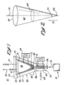
- a slush producing system 10 produces a slush 12 from a liquid 14 through removal of thermal energy.
- the slush 12 is a part solid/part liquid mixture.
- Some of the possible liquids 14 include oxygen, nitrogen, hydrogen, helium, water, and various compounds and mixtures.
- the slush 12 may be used in many applications.
- the slush 12 is directed in flow 16 to be placed in a cryogenic liquid propellant tank 18 to assist in the densification of the liquid propellant therein, such as described in U.S. Patent No. 5,644,920 to Lak et al. entitled “Liquid Propellant Densification,” and incorporated herein by reference in its entirety.
- Other embodiments of the invention may direct the slush to any type of cryogenic liquid tank or to any application that may benefit from using the produced slush.
- the slush producing system 10 comprises an insulated vessel 20 having an intermediate jacket 22 surrounding an interior wall 26.
- the intermediate jacket 22 is thermally connected to a temperature control device 24 to control the temperature of the vessel interior wall 26 of the vessel 20.
- Other embodiments of the invention may have other ways of adjusting the temperature of the vessel interior wall 26, including layers of inner jackets with independent thermally connected temperature control devises.
- Other embodiments of the invention may have the inner jacket 22 zoned to withdraw thermal energy at differing rates from different portions of the interior wall 26.
- an outer jacket 27 surrounds the intermediate jacket 22.
- the outer jacket 27 provides another layer of insulation for the insulated vessel 20.
- the insulation of the outer jacket 27 is provided in the form of a partial vacuum or essentially a vacuum in the space 29 between the intermediate and outer jackets.
- Other embodiments of the invention may have other forms of insulation in the outer jacket 27, may have multiple outer jackets, or may not have an outer jacket.
- the vessel interior wall 26 defines an inverted cone-shaped interior 28 with an apex 30 below a base 32.
- the inverted position of the interior 28 is used in slush producing devices 10 that produce slush 12 having a slush density greater than a density of the liquid 14, which applies to oxygen, nitrogen, hydrogen, and helium.
- Interiors of vessels in other embodiments of the invention may have the apex above the base for use with water, which has a liquid density greater than the density of slush made from water.
- the vessel 20 has a liquid feed 34 and a gas feed 35.
- the liquid feed 34 is directing liquid 14 into the vessel interior 28 through the vessel base 32.
- the gas feed 35 is for directing and/or removing gas 15 from the vessel interior 28.
- the gas 15 is used to control the pressure of the interior pressure of the vessel 20.
- Other embodiments of the invention may have multiple liquid and gas feeds, may have the feeds at other locations, and may have separate gas lines for feeding gas 15 to the vessel 20 and removing gas 15 from the vessel.
- Other embodiments of the invention may use a liquid for changing the pressure of the vessel interior 28.
- the pressure adjusting gas 15 or liquid in embodiments of the invention may be similar or dissimilar to the liquid 14 in the vessel interior 28.
- Other embodiments of the invention may have other ways to adjust the pressure in the vessel interior 28, such as a diaphragm or piston for changing the volume of the vessel interior.
- the jacket 22 cools the vessel interior wall 26
- the removal of thermal energy from the liquid in the proximity of the wall result in slush 12 forming.
- the slush moves downward to a collection portion 36 of vessel interior 28 at the apex 30.
- the slush 12 in the collection portion 36 of the vessel interior 28 exits through a valve 38 at the apex 30.
- the slush 12 is directed out of the vessel interior 28 and into a pressurization chamber 50 in the shown embodiment.
- Other embodiments of the invention may not have a pressurization chamber 50.
- the slush 12 in the pressurization chamber 50 may be pressurized by the introduction of gas or liquid through a pressurization line 52.
- Other embodiments of the invention may have a pressurization chamber that pressurizes the slush 12 through mechanical compaction or other means.
- the pressurization chamber 50 has a jacketed exterior 54 to remove additional thermal energy from the slush 12 in the chamber.
- Other embodiments of the invention may have other ways of removing thermal energy from the slush in the pressurization chamber 50.
- the slush 12 exits the pressurization chamber 50 through an exit valve 56 and is directed to the cryogenic liquid tank 18.
- the pressurization and/or additional removal of thermal energy from the slush 12 in the pressurization chamber 50 may substantially convert the slush to a solid.
- an inverted cone 60 represents the vessel interior 28 in three dimensions.
- the overall volume 62 of the cone 60 extends from the base 64 to the apex 66.
- the overall volume 62 has an average overall cross-sectional area 68 taken through a vertical axis 70 extending generally between the base 64 and the apex 66.
- the collection portion 72 has an average collection portion cross-sectional area 74 that is less than the average overall cross-sectional area 68.
- the difference in average cross-sectional areas 68 and 74 enable slush 12 formed on the vessel interior wall 26 to move down the wall and collect in the collection portion 72 in this embodiment.
- the vessel interior 62 would have the collection portion 72 above the base 64 for substances such as water that has a greater density in a liquid state compared to its solid state.
- inventions may have vessel interiors of other shapes, such as ellipsoidal, cylindrical with a conical end for the collection portion, pyramidal, tetrahedral, and a portion of a sphere.
- Other embodiments may have irregular surfaces for funneling the slush to the collection portion or for increased surface area for greater heat transfer between the liquid and the vessel walls.
- Embodiments of the invention may produce the slush as a batch, semi-batch, or continuous process.
- Embodiments of the invention may also include interior wall scrapers, agitators, or augurs to assist in moving and directing the slush to the collection portion.
Landscapes
- Engineering & Computer Science (AREA)
- Chemical & Material Sciences (AREA)
- Physics & Mathematics (AREA)
- Remote Sensing (AREA)
- Aviation & Aerospace Engineering (AREA)
- Organic Chemistry (AREA)
- Thermal Sciences (AREA)
- Mechanical Engineering (AREA)
- Combustion & Propulsion (AREA)
- General Engineering & Computer Science (AREA)
- Astronomy & Astrophysics (AREA)
- General Physics & Mathematics (AREA)
- Separation By Low-Temperature Treatments (AREA)
- Physical Or Chemical Processes And Apparatus (AREA)
- Hydrogen, Water And Hydrids (AREA)
- Filling Or Discharging Of Gas Storage Vessels (AREA)
- Treatment Of Sludge (AREA)
Abstract
Description
Claims (25)
- A cooling process for producing a slush with a slush density from a liquid with a liquid density comprising the steps of:(a) providing a cooling device comprising an interior wall that defines an interior space comprising:(I) a top and bottom;(II) an average overall cross-sectional area are taken through a vertical axis extending generally between the top and the bottom; and(III) a collection portion of the interior space having an average collection portion cross-sectional area taken through the vertical axis that is less than the average overall cross-sectional area;(b) placing the liquid in the interior space;(c) changing the density of a portion of the liquid to produce the slush through cooling at least a portion of interior wall and, whereby, at least a portion of the slush accumulates in the collection portion; and(d) removing the slush portion from the collection portion.
- The cooling process of claim 1, wherein the collection portion is located at the interior space bottom when the slush density is higher than the liquid density and the collection portion is located at the interior space top when slush density is less than the liquid density.
- The cooling process of claim 1 or 2,
further comprising the step of changing an interior space pressure, wherein the interior space of the cooling device is pressurizable or depressurizable. - The cooling process of claim 1, further comprising the step of changing the pressure of the slush portion.
- The cooling process of claim 4, wherein the changing the pressure step occurs before the removing step.
- The cooling process of claim 4, wherein the changing the pressure step occurs after the removing step.
- The cooling process of claim 4, further comprising the step of reducing thermal energy from the slush portion after the changing the pressure step.
- The cooling process of claim 7, further comprising the step of depressurizing the slush portion after the reducing thermal energy step.
- The cooling process of any of claim 5-8,
further comprising the step of using the slush portion to densify cryogenic liquid propellant. - The cooling process of claim 9, wherein the using the slush portion step comprises the step of placing the slush portion in a tank for holding the cryogenic liquid propellant.
- The cooling process of any of claim 5-10, further comprising the step of using the slush portion to densify cryogenic liquid propellant.
- The cooling process of any of claim 5-11, wherein the liquid comprises cryogenic liquid oxygen, cryogenic liquid nitrogen, cryogenic liquid hydrogen or cryogenic liquid helium.
- The cooling process of any of claim 5-12, wherein the liquid comprises water.
- The cooling process of any of claim 5-13, comprising the step of coordinating the placing the liquid step, changing the density step, and the removing the slush portion step to be performed as a batch, semi-batch, or continuous process.
- A first cryogenic liquid densification process comprising the steps of combining the first cryogenic liquid with a second cryogenic liquid that is at least partially solidified, wherein the first and second cryogenic liquids are of at least compatible chemical compositions.
- The process of any of claim 1-15, wherein the first cryogenic liquid is a cryogenic liquid propellant.
- A slush producing device comprising:(a) a jacketed vessel having an interior space comprising :(I) a top and a bottom;(II) an average overall cross-sectional area taken through a vertical axis extending generally between the top and the bottom;(III) a collection portion of the interior space having a average collection portion cross-sectional area taken through the vertical axis that is less than the average overall cross-sectional area; and(IV) a remainder portion of the interior space that is the region of the interior space next to the collection portion;(b) an inlet for receiving an inlet flow into the interior space;(c) a pressure isolation valve between the collection portion and the remainder portion of the interior space and;(d) an outlet for enabling an outlet flow to exit the collection portion.
- The slush producing device of claim 17, further comprising a cooling device about the collection portion.
- The slush producing device of claim 17, wherein the interior space remainder portion is enclosed and pressurizable to a different pressure than the collection portion.
- A slush producing system comprising:(a) a jacketed vessel comprising:(I) a vessel interior space comprising a top and bottom, an average overall cross-sectional area taken through a vertical axis extending generally between the top and the bottom, and a collection portion having an average collection portion cross-sectional area;(II) an inlet for receiving an inlet flow the vessel interior space; and(III) an outlet for enabling an outlet flow tot exit the collection portion; and(b) a pressurization device(c) comprising a pressurizable interior space with an inlet and an outlet, the inlet being functionally connected to the jacketed vessel outlet.
- The slush producing system or device according tot any of claims 17-20, wherein at least a conical portion of the vessel interior space has the general shape of a cone and the collection portion is located in the proximity of an apex of the conical portion, the bottom, and/or of the vessel interior space.
- The slush producing system or device according to any of claims 17-21, wherein the pressurization device comprises a cooling jacket about at least a portion of the pressurizable interior space of the pressurization device.
- The slush producing system of any of claims 17-22, wherein an outlet is functionally connected to an inlet of a cryogenic liquid tank.
- The slush producing system of any of claims 17-23, wherein the is functionally connected to an inlet of a cryogenic liquid propellant tank.
- A cooling process according to any of claims 1-16, using a device or system according to any of claims 17-24 and/or described in the proceeding specification including the annexed figures.
Applications Claiming Priority (2)
| Application Number | Priority Date | Filing Date | Title |
|---|---|---|---|
| US09/262,787 US6131397A (en) | 1999-03-04 | 1999-03-04 | Slush producing process and device |
| US262787 | 1999-03-04 |
Publications (3)
| Publication Number | Publication Date |
|---|---|
| EP1033543A2 true EP1033543A2 (en) | 2000-09-06 |
| EP1033543A3 EP1033543A3 (en) | 2001-03-14 |
| EP1033543B1 EP1033543B1 (en) | 2007-11-21 |
Family
ID=22999042
Family Applications (1)
| Application Number | Title | Priority Date | Filing Date |
|---|---|---|---|
| EP00200756A Expired - Lifetime EP1033543B1 (en) | 1999-03-04 | 2000-03-03 | Slush producing process and device |
Country Status (5)
| Country | Link |
|---|---|
| US (1) | US6131397A (en) |
| EP (1) | EP1033543B1 (en) |
| JP (1) | JP4709342B2 (en) |
| AU (1) | AU779749B2 (en) |
| DE (1) | DE60037154T2 (en) |
Cited By (1)
| Publication number | Priority date | Publication date | Assignee | Title |
|---|---|---|---|---|
| US7201018B2 (en) | 2003-01-28 | 2007-04-10 | Air Products And Chemicals, Inc. | Generation and delivery system for high pressure ultra high purity product |
Families Citing this family (9)
| Publication number | Priority date | Publication date | Assignee | Title |
|---|---|---|---|---|
| WO2004080892A1 (en) * | 2003-03-11 | 2004-09-23 | Mayekawa Mfg. Co., Ltd. | Process for producing slush nitrogen and apparatus therefor |
| EP1731481B1 (en) | 2004-02-06 | 2013-09-04 | Mayekawa Mfg. Co., Ltd. | Method and apparatus for producing slush nitrogen |
| US8844309B2 (en) * | 2010-03-15 | 2014-09-30 | Whirlpool Corporation | Fast ice making device |
| US10808967B2 (en) | 2017-01-16 | 2020-10-20 | Praxair Technology, Inc. | Refrigeration cycle for liquid oxygen densification |
| EP3765801B1 (en) * | 2018-03-13 | 2022-01-19 | Viglundsson, Thorsteinn I. | Method and apparatus for making wet snow |
| JP6589123B1 (en) * | 2019-01-28 | 2019-10-16 | アイスマン株式会社 | Ice slurry production system |
| CN114845644B (en) * | 2019-12-20 | 2026-03-06 | 波士顿科学国际有限公司 | Pharmaceutical delivery device |
| EP4041094A1 (en) * | 2020-01-06 | 2022-08-17 | Boston Scientific Scimed, Inc. | Agent delivery systems |
| KR102416845B1 (en) * | 2021-09-30 | 2022-07-06 | 고등기술연구원연구조합 | System for generating slush using cryogenic material |
Family Cites Families (17)
| Publication number | Priority date | Publication date | Assignee | Title |
|---|---|---|---|---|
| US2640627A (en) * | 1949-01-15 | 1953-06-02 | Vadolt Trust | Vapor recovery system for fuel tanks |
| US3389555A (en) * | 1962-01-22 | 1968-06-25 | Marquardt Corp | Hydrogen conversion and restorage work cycle |
| US3393152A (en) * | 1965-08-03 | 1968-07-16 | Air Reduction | Composition of matter and methods of making same |
| US3455117A (en) * | 1966-10-03 | 1969-07-15 | Martin Marietta Corp | Method and apparatus for cooling and subcooling fluids such as hydrogen |
| US3521458A (en) * | 1967-07-19 | 1970-07-21 | Air Reduction | Apparatus for making hydrogen slush using helium refrigerant |
| SE453778B (en) * | 1986-04-09 | 1988-02-29 | Peter Heinrich Erwin Margen | DEVICE FOR PREPARING ISSORJA |
| US4693737A (en) * | 1986-09-25 | 1987-09-15 | Liquid Carbonic Corporation | Remote cooling CO2 applications |
| JPH03260575A (en) * | 1990-03-09 | 1991-11-20 | Mitsubishi Heavy Ind Ltd | Liquid hydrogen tank for slush hydrogen |
| US5315530A (en) * | 1990-09-10 | 1994-05-24 | Rockwell International Corporation | Real-time control of complex fluid systems using generic fluid transfer model |
| WO1992007808A1 (en) * | 1990-10-29 | 1992-05-14 | Flynn Thomas M | Cryogenic fuels |
| US5220801A (en) * | 1992-04-20 | 1993-06-22 | Air Products And Chemicals, Inc. | Method and apparatus for maintenance of slush mixture at desired level during melt conditions |
| JPH06281321A (en) * | 1993-03-31 | 1994-10-07 | Nippon Sanso Kk | Method and apparatus for producing slush hydrogen |
| US5398515A (en) * | 1993-05-19 | 1995-03-21 | Rockwell International Corporation | Fluid management system for a zero gravity cryogenic storage system |
| US5402649A (en) * | 1993-09-02 | 1995-04-04 | Rockwell International Corporation | Spray-freeze slush hydrogen generator |
| JPH08285420A (en) * | 1995-04-18 | 1996-11-01 | Mitsubishi Heavy Ind Ltd | Slush hydrogen manufacturing apparatus and manufacturing method |
| DE19811315C2 (en) * | 1998-03-16 | 2000-08-03 | Steyr Daimler Puch Ag | Method and device for producing slush from liquefied gas |
| JP2000220961A (en) * | 1999-02-01 | 2000-08-08 | Mitsubishi Heavy Ind Ltd | Slush hydrogen production apparatus and production method |
-
1999
- 1999-03-04 US US09/262,787 patent/US6131397A/en not_active Expired - Lifetime
-
2000
- 2000-02-29 JP JP2000053641A patent/JP4709342B2/en not_active Expired - Lifetime
- 2000-03-01 AU AU19559/00A patent/AU779749B2/en not_active Expired
- 2000-03-03 DE DE60037154T patent/DE60037154T2/en not_active Expired - Lifetime
- 2000-03-03 EP EP00200756A patent/EP1033543B1/en not_active Expired - Lifetime
Cited By (1)
| Publication number | Priority date | Publication date | Assignee | Title |
|---|---|---|---|---|
| US7201018B2 (en) | 2003-01-28 | 2007-04-10 | Air Products And Chemicals, Inc. | Generation and delivery system for high pressure ultra high purity product |
Also Published As
| Publication number | Publication date |
|---|---|
| DE60037154D1 (en) | 2008-01-03 |
| DE60037154T2 (en) | 2008-10-02 |
| EP1033543B1 (en) | 2007-11-21 |
| AU1955900A (en) | 2000-09-07 |
| US6131397A (en) | 2000-10-17 |
| EP1033543A3 (en) | 2001-03-14 |
| AU779749B2 (en) | 2005-02-10 |
| JP2000258053A (en) | 2000-09-22 |
| JP4709342B2 (en) | 2011-06-22 |
Similar Documents
| Publication | Publication Date | Title |
|---|---|---|
| US6131397A (en) | Slush producing process and device | |
| US5281251A (en) | Process for shape casting of particle stabilized metal foam | |
| EP0295196B1 (en) | Apparatus and method for the rapid attainment of high hydrostatic pressures and concurrent delivery to a workpiece | |
| US4973358A (en) | Method of producing lightweight foamed metal | |
| US4942750A (en) | Apparatus and method for the rapid attainment of high hydrostatic pressures and concurrent delivery to a workpiece | |
| US6927421B2 (en) | Heat sink material | |
| US7648540B2 (en) | System for production of hydrogen with metal hydride and a method | |
| JP2004098170A (en) | Method and device for manufacturing flowable metal bubble | |
| EP1470262B1 (en) | Metal foam casting apparatus and method | |
| CN117279762A (en) | Pressed ceramic fluidics modules with porous and non-porous structures | |
| US5110542A (en) | Rapid densification of materials | |
| JPH0527563B2 (en) | ||
| EP1731481A1 (en) | Method and apparatus for producing slush nitrogen | |
| EP0357058A1 (en) | Method for casting powder | |
| SE440496B (en) | SET TO CONSOLIDATE POWDER IN A CONTAINER THROUGH EXTENSION OF PRESSURE ON THE OUTER OF THE CONTAINER AND APPARATUS FOR IMPLEMENTATION OF THE SET | |
| JPH08285420A (en) | Slush hydrogen manufacturing apparatus and manufacturing method | |
| KR20030081527A (en) | Refractory plug or brick for injecting gas into molten metal | |
| EP0388235A2 (en) | Method and apparatus for casting | |
| EP3868494B1 (en) | Isostatic pressing canister | |
| CA2251751C (en) | A process and plant for producing atomized metal powder, metal powder and the use of the metal powder | |
| JPH07278607A (en) | Powder molding method using split mold | |
| CN114433820A (en) | A system for preparing ultrafine-grained metallic materials by liquid assembly method and ultrafine-grained metallic materials | |
| WO1980001489A1 (en) | Cold crucible semiconductor deposition process and apparatus | |
| US6076362A (en) | Process and apparatus for cooling a continuously inflowing liquid in vacuo | |
| Wang et al. | Study on Crack‐like Pores of Al Foams Made via the Powder‐Metallurgy Route |
Legal Events
| Date | Code | Title | Description |
|---|---|---|---|
| PUAI | Public reference made under article 153(3) epc to a published international application that has entered the european phase |
Free format text: ORIGINAL CODE: 0009012 |
|
| AK | Designated contracting states |
Kind code of ref document: A2 Designated state(s): DE FR GB IT |
|
| AX | Request for extension of the european patent |
Free format text: AL;LT;LV;MK;RO;SI |
|
| PUAL | Search report despatched |
Free format text: ORIGINAL CODE: 0009013 |
|
| AK | Designated contracting states |
Kind code of ref document: A3 Designated state(s): AT BE CH CY DE DK ES FI FR GB GR IE IT LI LU MC NL PT SE |
|
| AX | Request for extension of the european patent |
Free format text: AL;LT;LV;MK;RO;SI |
|
| 17P | Request for examination filed |
Effective date: 20010824 |
|
| AKX | Designation fees paid |
Free format text: DE FR GB NL |
|
| RBV | Designated contracting states (corrected) |
Designated state(s): DE FR GB IT |
|
| 17Q | First examination report despatched |
Effective date: 20030306 |
|
| 17Q | First examination report despatched |
Effective date: 20030306 |
|
| GRAP | Despatch of communication of intention to grant a patent |
Free format text: ORIGINAL CODE: EPIDOSNIGR1 |
|
| RAP1 | Party data changed (applicant data changed or rights of an application transferred) |
Owner name: THE BOEING COMPANY |
|
| GRAS | Grant fee paid |
Free format text: ORIGINAL CODE: EPIDOSNIGR3 |
|
| GRAA | (expected) grant |
Free format text: ORIGINAL CODE: 0009210 |
|
| AK | Designated contracting states |
Kind code of ref document: B1 Designated state(s): DE FR GB IT |
|
| REG | Reference to a national code |
Ref country code: GB Ref legal event code: FG4D |
|
| REF | Corresponds to: |
Ref document number: 60037154 Country of ref document: DE Date of ref document: 20080103 Kind code of ref document: P |
|
| ET | Fr: translation filed | ||
| RAP2 | Party data changed (patent owner data changed or rights of a patent transferred) |
Owner name: THE BOEING COMPANY |
|
| PLBE | No opposition filed within time limit |
Free format text: ORIGINAL CODE: 0009261 |
|
| STAA | Information on the status of an ep patent application or granted ep patent |
Free format text: STATUS: NO OPPOSITION FILED WITHIN TIME LIMIT |
|
| 26N | No opposition filed |
Effective date: 20080822 |
|
| REG | Reference to a national code |
Ref country code: FR Ref legal event code: PLFP Year of fee payment: 17 |
|
| REG | Reference to a national code |
Ref country code: FR Ref legal event code: PLFP Year of fee payment: 18 |
|
| REG | Reference to a national code |
Ref country code: FR Ref legal event code: PLFP Year of fee payment: 19 |
|
| PGFP | Annual fee paid to national office [announced via postgrant information from national office to epo] |
Ref country code: DE Payment date: 20190327 Year of fee payment: 20 Ref country code: FR Payment date: 20190325 Year of fee payment: 20 Ref country code: IT Payment date: 20190322 Year of fee payment: 20 |
|
| PGFP | Annual fee paid to national office [announced via postgrant information from national office to epo] |
Ref country code: GB Payment date: 20190404 Year of fee payment: 20 |
|
| REG | Reference to a national code |
Ref country code: DE Ref legal event code: R071 Ref document number: 60037154 Country of ref document: DE |
|
| REG | Reference to a national code |
Ref country code: GB Ref legal event code: PE20 Expiry date: 20200302 |
|
| PG25 | Lapsed in a contracting state [announced via postgrant information from national office to epo] |
Ref country code: GB Free format text: LAPSE BECAUSE OF EXPIRATION OF PROTECTION Effective date: 20200302 |