EP1033488A2 - Fuel injector - Google Patents
Fuel injector Download PDFInfo
- Publication number
- EP1033488A2 EP1033488A2 EP00301797A EP00301797A EP1033488A2 EP 1033488 A2 EP1033488 A2 EP 1033488A2 EP 00301797 A EP00301797 A EP 00301797A EP 00301797 A EP00301797 A EP 00301797A EP 1033488 A2 EP1033488 A2 EP 1033488A2
- Authority
- EP
- European Patent Office
- Prior art keywords
- valve member
- seating
- fuel
- bore
- fuel injector
- Prior art date
- Legal status (The legal status is an assumption and is not a legal conclusion. Google has not performed a legal analysis and makes no representation as to the accuracy of the status listed.)
- Granted
Links
- 239000000446 fuel Substances 0.000 title claims abstract description 122
- 230000005540 biological transmission Effects 0.000 claims abstract description 5
- 238000002347 injection Methods 0.000 claims description 22
- 239000007924 injection Substances 0.000 claims description 22
- 238000005553 drilling Methods 0.000 claims description 8
- 238000011144 upstream manufacturing Methods 0.000 claims description 2
- 238000002485 combustion reaction Methods 0.000 description 4
- 238000004519 manufacturing process Methods 0.000 description 4
- 230000015572 biosynthetic process Effects 0.000 description 3
- 238000005755 formation reaction Methods 0.000 description 3
- 239000007921 spray Substances 0.000 description 3
- 230000004323 axial length Effects 0.000 description 2
- 238000007493 shaping process Methods 0.000 description 2
- 238000004513 sizing Methods 0.000 description 2
- 238000004891 communication Methods 0.000 description 1
- 230000006835 compression Effects 0.000 description 1
- 238000007906 compression Methods 0.000 description 1
- 238000010276 construction Methods 0.000 description 1
- 230000000694 effects Effects 0.000 description 1
- 230000005684 electric field Effects 0.000 description 1
- 239000012530 fluid Substances 0.000 description 1
- 230000003993 interaction Effects 0.000 description 1
- 230000004048 modification Effects 0.000 description 1
- 238000012986 modification Methods 0.000 description 1
Images


Classifications
-
- F—MECHANICAL ENGINEERING; LIGHTING; HEATING; WEAPONS; BLASTING
- F02—COMBUSTION ENGINES; HOT-GAS OR COMBUSTION-PRODUCT ENGINE PLANTS
- F02M—SUPPLYING COMBUSTION ENGINES IN GENERAL WITH COMBUSTIBLE MIXTURES OR CONSTITUENTS THEREOF
- F02M61/00—Fuel-injectors not provided for in groups F02M39/00 - F02M57/00 or F02M67/00
- F02M61/16—Details not provided for in, or of interest apart from, the apparatus of groups F02M61/02 - F02M61/14
- F02M61/162—Means to impart a whirling motion to fuel upstream or near discharging orifices
- F02M61/163—Means being injection-valves with helically or spirally shaped grooves
-
- F—MECHANICAL ENGINEERING; LIGHTING; HEATING; WEAPONS; BLASTING
- F02—COMBUSTION ENGINES; HOT-GAS OR COMBUSTION-PRODUCT ENGINE PLANTS
- F02M—SUPPLYING COMBUSTION ENGINES IN GENERAL WITH COMBUSTIBLE MIXTURES OR CONSTITUENTS THEREOF
- F02M45/00—Fuel-injection apparatus characterised by having a cyclic delivery of specific time/pressure or time/quantity relationship
- F02M45/02—Fuel-injection apparatus characterised by having a cyclic delivery of specific time/pressure or time/quantity relationship with each cyclic delivery being separated into two or more parts
- F02M45/04—Fuel-injection apparatus characterised by having a cyclic delivery of specific time/pressure or time/quantity relationship with each cyclic delivery being separated into two or more parts with a small initial part, e.g. initial part for partial load and initial and main part for full load
- F02M45/08—Injectors peculiar thereto
- F02M45/086—Having more than one injection-valve controlling discharge orifices
-
- F—MECHANICAL ENGINEERING; LIGHTING; HEATING; WEAPONS; BLASTING
- F02—COMBUSTION ENGINES; HOT-GAS OR COMBUSTION-PRODUCT ENGINE PLANTS
- F02M—SUPPLYING COMBUSTION ENGINES IN GENERAL WITH COMBUSTIBLE MIXTURES OR CONSTITUENTS THEREOF
- F02M61/00—Fuel-injectors not provided for in groups F02M39/00 - F02M57/00 or F02M67/00
- F02M61/04—Fuel-injectors not provided for in groups F02M39/00 - F02M57/00 or F02M67/00 having valves, e.g. having a plurality of valves in series
- F02M61/10—Other injectors with elongated valve bodies, i.e. of needle-valve type
-
- F—MECHANICAL ENGINEERING; LIGHTING; HEATING; WEAPONS; BLASTING
- F02—COMBUSTION ENGINES; HOT-GAS OR COMBUSTION-PRODUCT ENGINE PLANTS
- F02M—SUPPLYING COMBUSTION ENGINES IN GENERAL WITH COMBUSTIBLE MIXTURES OR CONSTITUENTS THEREOF
- F02M61/00—Fuel-injectors not provided for in groups F02M39/00 - F02M57/00 or F02M67/00
- F02M61/16—Details not provided for in, or of interest apart from, the apparatus of groups F02M61/02 - F02M61/14
- F02M61/18—Injection nozzles, e.g. having valve seats; Details of valve member seated ends, not otherwise provided for
Definitions
- This invention relates to a fuel injector for use in supplying fuel under pressure to a combustion space of an engine.
- the invention relates to a fuel injector in which a characteristic of the fuel injector, for example the injection rate or spray form, can be altered, in use.
- an injection cycle may include an initial phase during which fuel is supplied at a relatively low rate and a subsequent phase during which fuel is delivered at a higher rate.
- other fuel injection characteristics may be varied. It is an object of the invention to provide a fuel injector meeting these requirements.
- a fuel injector comprising a nozzle body provided with a first bore and defining a first seating, a valve member engageable with the first seating to control fuel flow from the first bore towards a first outlet opening located downstream of the first seating, the valve member being provided with a second bore defining a second seating, a valve needle being slidable within the second bore and being engageable with the second seating to control fuel flow from the second bore towards a second outlet opening provided in the valve member, and a transmission arrangement whereby movement of the valve needle beyond a predetermined position is transmitted to the valve member.
- the nozzle body may be provided with a plurality of first outlet openings and the valve member may be provided with a plurality of second outlet openings.
- the first and second outlet openings may be located such that, when the valve member engages the first seating and the valve needle is lifted from the second seating, the first and second outlet openings are arranged in series with one another, movement of the valve member away from the first seating permitting fuel delivery through the first outlet opening, by-passing the second outlet opening. It will be appreciated, that depending upon the shape and size of the first and second outlet openings, the fuel delivery rate or other fuel injection characteristics may be varied by varying the distance by which the valve needle is moved.
- the number of first outlet openings may be equal to the number of second outlet openings. Alternatively, fewer second outlet openings may be provided, in which case only some of the first outlet openings are used to deliver fuel whilst the valve member engages the first seating and the valve needle is lifted away from the second seating.
- valve member may include a tip portion provided with an opening to allow passage of fuel from the second bore to the first outlet opening, the tip portion being arranged to partially cover the first outlet opening when the valve member engages the first seating and being moveable to a position in which the first outlet opening is not covered by the tip portion.
- the second outlet opening in the valve member may be an axially extending opening. Movement of the valve needle away from the second seating by an amount which does not exceed a predetermined amount permits fuel to flow from the second bore in the valve member through an axially extending opening into the first outlet opening. As the first outlet opening is partially obscured by the tip portion, the rate at which fuel is delivered is limited. As movement of the valve needle is not transmitted to the valve member, fuel does not flow past the first seating directly to the first outlet opening. Thus, fuel delivery occurs at a relatively low fuel delivery rate.
- valve needle away from the second seating beyond the predetermined amount results in movement of the valve member away from the first seating and thus permits fuel to flow from the first bore, past the first seating, directly to the first outlet opening, therefore by-passing the axially extending opening in the valve member.
- the movement of the valve member results in the tip portion moving to a position in which it does not throttle fuel delivery, thereby permitting a higher fuel delivery rate.
- the tip portion may be of truncated, conical form, the tip portion partially covering the first outlet opening in the nozzle body when the valve member engages the first seating such that fuel flow through the opening is throttled, thereby permitting a low fuel delivery rate.
- This embodiment of the invention provides the advantage that accurate radial guidance of the valve needle is not essential.
- the construction of the fuel injector is therefore less complex and manufacture is simplified.
- the first outlet opening can be located at a lower axial position in the nozzle body, as there are no openings in the valve needle with which the first outlet opening must align.
- the allowable pressure limit for the injector can be increased.
- the fuel injector conveniently includes a sac formed downstream of the first seating and communicating with the first outlet opening formed in the nozzle body, the axially extending opening in the valve member communicating with the sac to enable fuel to flow through the axially extending opening into the sac and out through the first outlet opening in the nozzle body.
- the sac is of truncated conical form so as to minimise the dead volume.
- the fuel injector illustrated, in part, in Figure 1 comprises a nozzle body 10 provided with a blind bore 11.
- the bore 11 defines, adjacent its blind end, a seating surface 12 with which a frusto-conical end region of a valve member 13 is engageable to control communication between the bore 11 and a plurality of first outlet openings 14 located downstream of the seating.
- the valve member 13 is provided with a blind bore 15 within which a tip region 16 a of a valve needle 16 is received.
- the tip region 16 a is engageable with a second seating 17, a plurality of second outlet openings 18 opening into the bore 15 downstream of the line or area over which the valve needle 16 is engageable with the second seating 17.
- the blind bore 15 is shaped to include a region of enlarged diameter which defines, with the needle 16, a chamber 19 upstream of the second seating 17 which communicates through drillings 20 with the interior of the bore 11.
- the bore 11 is arranged to receive fuel under high pressure from an appropriate fuel source, for example the common rail of a common rail fuel system which, in use, is charged to a suitably high pressure by an appropriate high pressure fuel pump. As illustrated in Figure 1, the bore 11 receives the fuel under high pressure through a supply passage 21 which communicates with an annular gallery 22 defined by a part of the bore 11 of enlarged diameter.
- the needle 16 is shaped to include, at its end remote from the tip region 16 a thereof, a region of 16 b diameter substantially equal to the diameter of the adjacent part of the bore 11. Engagement between this part of the needle 16 and the wall defining the bore 11 serves to guide the needle 16 for sliding movement within the bore 11.
- the needle 16 is provided with a plurality of grooves or flutes 16 c in a known manner.
- the valve needle 16 is provided with an opening through which a load transmitting pin 23 extends, the pin 23 conveniently being an interference fit in the opening to secure the pin 23 to the needle 16.
- the ends of the pin 23 project radially from the valve needle 16 and extend into openings 24 provided in the valve member 13.
- the openings 24 are of width substantially equal to the diameter of the pin 23 but, in the orientation illustrated, are of height greater than the diameter of the pin 23. The positioning of the pin 23 and the openings 24 are such that, when the valve needle 16 engages the second seating 17 and the valve member 13 engages the first seating 12, the pin 23 is spaced slightly from the lower end of each opening 24, and is spaced by a greater distance from the upper end of each opening 24.
- the upper end region of the needle 16 is provided with a radially extending projection or pin 25 which is received within a groove or slot 26 formed in the wall defining the bore 11, the interaction between the pin 25 and the groove or slot 26 is such as to prevent or significantly restrict angular movement of the needle 16 relative to the bore 11, but to permit axial movement of the needle 16. It will be appreciated that as angular movement between the needle 16 and the nozzle body 10 is inhibited, and the engagement of the pin 23 within the openings 24 substantially prevents angular movement occurring between the needle 16 and the valve member 13, that angular movement of the valve member 13 is not permitted.
- the positioning of the first and second groups of openings 14, 18 can be chosen to ensure that when the valve member 13 engages the first seating surface 12, each of the second openings 18 communicates with a respective one of the first openings 14.
- the injector includes an appropriate actuator arrangement which is used to control movement of the valve needle 16.
- the actuator arrangement may take any suitable form and may, for example, comprise a piezoelectric stack arrangement, the axial length of the piezoelectric stack varying depending upon the magnitude of an electric field applied thereto.
- the needle 16 may be coupled directly to the piezoelectric stack, in order to compensate for changes in the axial length of the piezoelectric stack resulting, for example, from thermal expansion, a piston member may be located between the needle 16 and the piezoelectric stack, the piston member and needle 16 together defining a chamber which communicates through a restriction with a suitable fluid source, for example the supply passage 21.
- Figures 1 and 2 illustrate the injector in an operating condition in which fuel is not to be delivered.
- the actuator applies a downward force to the needle 16 sufficient to ensure that the needle 16 engages the second seating 17, the downward force being transmitted through the needle to the valve member 13 and ensuring that the valve member 13 engages the first seating 12. Due to the engagement between the valve needle 16 and the second seating 17 and between the valve member 13 and the first seating 12, it will be appreciated that fuel delivery is not permitted.
- the fuel flows through the second openings 18 to the first openings 14 and is delivered to a combustion space of the engine with which the injector is associated. It will be appreciated that the rate at which fuel is injected and the other injection characteristics depend upon the sizes of the first and second openings 14, 18 as well as the number of openings provided and the shapes of the openings. As the valve member 13 engages the first seating 12, it will be appreciated that fuel is unable to flow directly to the first openings 14.
- valve member 13 will remain in engagement with the first seating 12 due to the action of the fuel under pressure within the bore 11, if desired, a suitable spring may be provided between the valve member 13 and the needle 16 to apply a suitable downward biasing force to the valve member 13.
- the delivery of fuel may be terminated by re-applying the original downward force to the needle 16 to return the needle 16 to the position illustrated in Figures 1 and 2.
- the magnitude of the downward force applied to the needle 16 may be further reduced, the fuel pressure within the bore 11 causing additional movement of the needle 16 in an upward direction.
- the continued movement of the needle 16 results in the pin 23 moving into engagement with the ends of the openings 24, further movement of the needle 16 being transmitted to the valve member 13 through the pin 23, lifting the valve member 13 from the first seating 12 and permitting fuel to flow from the bore directly to the first openings 14.
- Such a position is illustrated in Figure 4.
- the flow of fuel to the first openings 14 may bypass the second openings 18, and as a result, the rate at which fuel is delivered or other injection characteristics may be altered depending on the relative shapes and sizes of the first and second openings 14, 18.
- the shaping of the entry end of an opening 14, 18 can have an effect on the fuel flow rate through that opening. For example, for a given diameter of opening 14, 18, the fuel flow rate therethrough will be greater if the entry end of the opening is flared outwardly, the wall of the flare being radiused, than if the entry end of the opening is plain, and such shaping can be utilised in the design of the injector to "tune" its operating characteristics.
- termination of injection may be achieved by re-applying the original downward force to the needle 16 causing the needle 16 and valve member 13 to return to the position illustrated in Figures 1 and 2.
- the sizing of the drillings 20 may be selected to achieve an appropriate pressure drop between the bore 11 and the chamber 19.
- FIG. 5 illustrates a modification to the arrangement illustrated in Figure 1 intended to ensure that the valve member 13 remains concentric with the first seating 12 when the valve member 13 is lifted from the first seating 12.
- the bore 11 is shaped to include a guide region 11 la of diameter substantially equal to the diameter of the adjacent part of the valve member 13.
- valve member 13 is guided for sliding movement within the bore 11.
- valve member 13 is conveniently provided with a plurality of flats 13 a or other formations defining a flow path between the valve member 13 and the guide region 11 a .
- Figure 5 further differs from that of Figure 1 in that the pin 23 is an interference fit within openings 24 provided in the valve member 13, the pin 23 riding within a slot or other kind of opening 24 a formed in the valve needle 16.
- the pin 23 further projects beyond part of the valve member 13 and rides within a groove 26 a formed in the nozzle body 10 to restrict angular movement between the valve member 13 and the nozzle body 10, thereby ensuring that the first and second openings 14, 18 align with one another when the valve member 13 engages the first seating 12.
- valve member 13 is provided with the same number of second openings 18 as the nozzle body 10 is provided with first openings 14, it will be appreciated that the valve member 13 may be provided with fewer second openings, in which case, when the valve member 13 engages the first seating 12, and the needle 16 is lifted from the second seating 17, fuel injection through only some of the first openings 14 will occur, fuel injection through the remaining openings commencing upon movement of the valve member 13 away from the first seating 12. It will be appreciated that, in such an arrangement, the shape of the spray formation may be varied as well as the rate at which fuel is delivered by varying the distance through which the valve needle 16 is lifted, in use.
- valve member 13 may be introduced into the bore 11 and held in position whilst the second openings 18 are drilled through the first openings 14. Such drilling may simply used to mark the locations in which the second openings 18 are to be formed, or the second openings may be completely drilled during such an operation.
- Figure 7 illustrates an arrangement which is largely similar to that of Figure 5, but in which the valve member 13 is provided with a single, axially extending opening 18 which communicates with a sac formed downstream of the first seating 12, the sac communicating with at least one of the first outlet openings 14. Further first outlet openings 14 are provided which do not communicate with the sac and which are covered by the valve member 13 when the valve member 13 engages the first seating 12.
- the initial movement of the valve needle 16 permits fuel delivery to the sac and the first openings 14 which communicate with the sac, further movement of the needle 16 lifting the valve member 13 away from the first seating and permitting fuel delivery through all of the first openings 14.
- Figures 8 and 9 show a further alternative embodiment of the invention in which the fuel injector includes a nozzle body 10 provided with a blind bore 11 in which a tip portion 27 of the valve member 13 is provided with an axially extending opening 28, located downstream of the second seating 17, such that when the valve needle 16 is lifted away from the second seating 17, fuel from within the bore 11 can flow past the seating 17 through the opening 28.
- the tip portion 27 of the valve member 13 is of truncated, conical form, as can be most clearly seen in Figure 8, such that, when the valve member 13 is in engagement with the seating 12, the truncated tip portion partially covers the openings 14.
- the tip portion 27 of the valve member 13 is truncated such that, with the valve member 13 engaging the seating 12, the flow area on entry to the outlet openings 14 is approximately half that of the flow area presented by each opening 14 if exposed.
- the flow of fuel through the openings 14 is throttled to permit relatively low fuel delivery rates.
- the axially extending opening 28 in the valve member 13 communicates with a sac 30 formed downstream of the first seating 12, the sac 30 communicating with the outlet openings 14 formed in the nozzle body 10 to enable fuel to flow through the axially opening 28 into the sac 30 and out through the outlet openings 14, as will be described hereinafter.
- the sac in a conventional fuel injector, from which fuel flows to the fuel injection outlets, is generally of conical form.
- the sac 30 in the fuel injector of the present invention is of truncated conical form, thus minimising the dead volume.
- valve needle 16 When injection of fuel is to commence, the magnitude of the downward force applied to the valve needle 16 is reduced. As a result, a point will be reached beyond which the fuel pressure within the bore 11 will apply a sufficiently large magnitude force to the valve needle 16 to cause the valve needle to lift away from the second seating 17 (i.e. out of the position shown in Figures 1 and 2). Provided the distance moved by the valve needle 16 is sufficiently small that the pin 23 remains spaced from the upper ends of the openings 24, the movement of the valve needle 16 is not transmitted to the valve member 13, and the fuel pressure within the bore 11 acting upon the valve member 13 will ensure that the valve member 13 remains in engagement with the first seating 12.
- termination of injection may be achieved by re-applying the original downward force to the valve needle 16 causing the needle 16 and valve member 13 to return to the position illustrated in Figures 1 and 2.
- the sizing of the drillings 20 may be selected to achieve an appropriate pressure drop between the bore 11 and the chamber 19.
- valve needle 16 can be lifted from the position illustrated in Figures 8 and 9 quickly so that fuel can immediately flow from the bore 11 directly to the openings 14, without the intermediate step of flowing through the axially extending opening 28 in the valve member 13, as described previously.
- the fuel injector in Figures 8 and 9 provides the advantage that it is simpler to manufacture as the angular orientation of the inner valve needle 16 within the bore of the valve member 13 is not so critical.
- the invention also provides the advantage that the openings 14 can be located at a lower axial position in the nozzle body 10, as there are no openings in the valve member 13 with which the openings 14 must align, and thus the allowable pressure limit for the nozzle body 10 is increased.
- Each of the embodiments described hereinbefore may be modified in such a manner as to includes several rows of openings in the nozzle body. Further, if desired and if sufficient space is available, a second valve member, and further valve members, may be carried by the valve member to permit further levels of injection rate or other injection characteristics to be provided.
- valve member 13 and the bore 11 may be arranged such that movement of the valve member is guided within the bore, as shown in Figures 5 to 7.
Landscapes
- Engineering & Computer Science (AREA)
- Chemical & Material Sciences (AREA)
- Combustion & Propulsion (AREA)
- Mechanical Engineering (AREA)
- General Engineering & Computer Science (AREA)
- Fuel-Injection Apparatus (AREA)
Abstract
Description
- This invention relates to a fuel injector for use in supplying fuel under pressure to a combustion space of an engine. In particular, the invention relates to a fuel injector in which a characteristic of the fuel injector, for example the injection rate or spray form, can be altered, in use.
- It has been found that, with compression ignition internal combustion engines, the levels of noise and particulate emissions produced by the engine can be reduced by varying the rate at which fuel is supplied during each fuel injection cycle. For example, an injection cycle may include an initial phase during which fuel is supplied at a relatively low rate and a subsequent phase during which fuel is delivered at a higher rate. Alternatively, or additionally, other fuel injection characteristics may be varied. It is an object of the invention to provide a fuel injector meeting these requirements.
- According to the present invention there is provided a fuel injector comprising a nozzle body provided with a first bore and defining a first seating, a valve member engageable with the first seating to control fuel flow from the first bore towards a first outlet opening located downstream of the first seating, the valve member being provided with a second bore defining a second seating, a valve needle being slidable within the second bore and being engageable with the second seating to control fuel flow from the second bore towards a second outlet opening provided in the valve member, and a transmission arrangement whereby movement of the valve needle beyond a predetermined position is transmitted to the valve member.
- The nozzle body may be provided with a plurality of first outlet openings and the valve member may be provided with a plurality of second outlet openings.
- The first and second outlet openings may be located such that, when the valve member engages the first seating and the valve needle is lifted from the second seating, the first and second outlet openings are arranged in series with one another, movement of the valve member away from the first seating permitting fuel delivery through the first outlet opening, by-passing the second outlet opening. It will be appreciated, that depending upon the shape and size of the first and second outlet openings, the fuel delivery rate or other fuel injection characteristics may be varied by varying the distance by which the valve needle is moved.
- The number of first outlet openings may be equal to the number of second outlet openings. Alternatively, fewer second outlet openings may be provided, in which case only some of the first outlet openings are used to deliver fuel whilst the valve member engages the first seating and the valve needle is lifted away from the second seating.
- Alternatively the valve member may include a tip portion provided with an opening to allow passage of fuel from the second bore to the first outlet opening, the tip portion being arranged to partially cover the first outlet opening when the valve member engages the first seating and being moveable to a position in which the first outlet opening is not covered by the tip portion.
- The second outlet opening in the valve member may be an axially extending opening. Movement of the valve needle away from the second seating by an amount which does not exceed a predetermined amount permits fuel to flow from the second bore in the valve member through an axially extending opening into the first outlet opening. As the first outlet opening is partially obscured by the tip portion, the rate at which fuel is delivered is limited. As movement of the valve needle is not transmitted to the valve member, fuel does not flow past the first seating directly to the first outlet opening. Thus, fuel delivery occurs at a relatively low fuel delivery rate. Further movement of the valve needle away from the second seating beyond the predetermined amount results in movement of the valve member away from the first seating and thus permits fuel to flow from the first bore, past the first seating, directly to the first outlet opening, therefore by-passing the axially extending opening in the valve member. The movement of the valve member results in the tip portion moving to a position in which it does not throttle fuel delivery, thereby permitting a higher fuel delivery rate.
- The tip portion may be of truncated, conical form, the tip portion partially covering the first outlet opening in the nozzle body when the valve member engages the first seating such that fuel flow through the opening is throttled, thereby permitting a low fuel delivery rate.
- This embodiment of the invention provides the advantage that accurate radial guidance of the valve needle is not essential. The construction of the fuel injector is therefore less complex and manufacture is simplified. Additionally, the first outlet opening can be located at a lower axial position in the nozzle body, as there are no openings in the valve needle with which the first outlet opening must align. Thus, the allowable pressure limit for the injector can be increased.
- The fuel injector conveniently includes a sac formed downstream of the first seating and communicating with the first outlet opening formed in the nozzle body, the axially extending opening in the valve member communicating with the sac to enable fuel to flow through the axially extending opening into the sac and out through the first outlet opening in the nozzle body. Preferably, the sac is of truncated conical form so as to minimise the dead volume.
- The invention will further be described, by way of example, with reference to the accompanying drawings, in which:
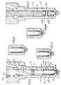
- Figure 1 is a sectional view of part of a fuel injector in accordance with an embodiment;
- Figures 2, 3 and 4 are views illustrating operation of the injector of Figure 1;
- Figure 5 is a view similar to Figure 1 illustrating a second embodiment;
- Figure 6 is a perspective view of the valve member of the injector of Figure 5;
- Figure 7 is a view similar to Figure 1 illustrating a third embodiment;
- Figure 8 is a view similar to Figure 1 illustrating a fourth embodiment; and
- Figure 9 is an enlarged sectional view of a part of the fuel injector in Figure 8.
-
- The fuel injector illustrated, in part, in Figure 1 comprises a
nozzle body 10 provided with ablind bore 11. Thebore 11 defines, adjacent its blind end, aseating surface 12 with which a frusto-conical end region of avalve member 13 is engageable to control communication between thebore 11 and a plurality offirst outlet openings 14 located downstream of the seating. - The
valve member 13 is provided with ablind bore 15 within which a tip region 16a of avalve needle 16 is received. The tip region 16a is engageable with asecond seating 17, a plurality ofsecond outlet openings 18 opening into thebore 15 downstream of the line or area over which thevalve needle 16 is engageable with thesecond seating 17. - The
blind bore 15 is shaped to include a region of enlarged diameter which defines, with theneedle 16, achamber 19 upstream of thesecond seating 17 which communicates throughdrillings 20 with the interior of thebore 11. Thebore 11 is arranged to receive fuel under high pressure from an appropriate fuel source, for example the common rail of a common rail fuel system which, in use, is charged to a suitably high pressure by an appropriate high pressure fuel pump. As illustrated in Figure 1, thebore 11 receives the fuel under high pressure through asupply passage 21 which communicates with anannular gallery 22 defined by a part of thebore 11 of enlarged diameter. - The
needle 16 is shaped to include, at its end remote from the tip region 16a thereof, a region of 16b diameter substantially equal to the diameter of the adjacent part of thebore 11. Engagement between this part of theneedle 16 and the wall defining thebore 11 serves to guide theneedle 16 for sliding movement within thebore 11. In order to permit fuel to flow from theannular gallery 22 towards the scatings and openings of thenozzle body 10 andvalve member 13, theneedle 16 is provided with a plurality of grooves or flutes 16c in a known manner. - The
valve needle 16 is provided with an opening through which aload transmitting pin 23 extends, thepin 23 conveniently being an interference fit in the opening to secure thepin 23 to theneedle 16. The ends of thepin 23 project radially from thevalve needle 16 and extend intoopenings 24 provided in thevalve member 13. Theopenings 24 are of width substantially equal to the diameter of thepin 23 but, in the orientation illustrated, are of height greater than the diameter of thepin 23. The positioning of thepin 23 and theopenings 24 are such that, when thevalve needle 16 engages thesecond seating 17 and thevalve member 13 engages thefirst seating 12, thepin 23 is spaced slightly from the lower end of each opening 24, and is spaced by a greater distance from the upper end of each opening 24. - The upper end region of the
needle 16 is provided with a radially extending projection orpin 25 which is received within a groove orslot 26 formed in the wall defining thebore 11, the interaction between thepin 25 and the groove orslot 26 is such as to prevent or significantly restrict angular movement of theneedle 16 relative to thebore 11, but to permit axial movement of theneedle 16. It will be appreciated that as angular movement between theneedle 16 and thenozzle body 10 is inhibited, and the engagement of thepin 23 within theopenings 24 substantially prevents angular movement occurring between theneedle 16 and thevalve member 13, that angular movement of thevalve member 13 is not permitted. As angular movement of thevalve member 13 is not permitted, the positioning of the first and second groups ofopenings valve member 13 engages thefirst seating surface 12, each of thesecond openings 18 communicates with a respective one of thefirst openings 14. - Although not illustrated in Figure 1, the injector includes an appropriate actuator arrangement which is used to control movement of the
valve needle 16. The actuator arrangement may take any suitable form and may, for example, comprise a piezoelectric stack arrangement, the axial length of the piezoelectric stack varying depending upon the magnitude of an electric field applied thereto. Although theneedle 16 may be coupled directly to the piezoelectric stack, in order to compensate for changes in the axial length of the piezoelectric stack resulting, for example, from thermal expansion, a piston member may be located between theneedle 16 and the piezoelectric stack, the piston member andneedle 16 together defining a chamber which communicates through a restriction with a suitable fluid source, for example thesupply passage 21. - Figures 1 and 2 illustrate the injector in an operating condition in which fuel is not to be delivered. In this condition, the actuator applies a downward force to the
needle 16 sufficient to ensure that theneedle 16 engages thesecond seating 17, the downward force being transmitted through the needle to thevalve member 13 and ensuring that thevalve member 13 engages thefirst seating 12. Due to the engagement between thevalve needle 16 and thesecond seating 17 and between thevalve member 13 and thefirst seating 12, it will be appreciated that fuel delivery is not permitted. - When injection of fuel is to commence, the magnitude of the downward force applied to the
needle 16 is reduced. As a result, a point will be reached beyond which the fuel pressure within thebore 11 will apply a sufficiently large magnitude force to theneedle 16 to cause theneedle 16 to lift away from thesecond seating 17. Provided the distance moved by theneedle 16 is sufficiently small that thepin 23 remains spaced from the upper ends of theopenings 24, the movement of theneedle 16 is not transmitted to thevalve member 13, and the fuel pressure within thebore 11 acting upon thevalve member 13 will ensure that thevalve member 13 remains in engagement with thefirst seating 12. Such a position is illustrated in Figure 3. In such circumstances, fuel is able to flow from thebore 11 through thedrillings 20 to thechamber 19, and between theneedle 16 and thesecond seating 17 to thesecond openings 18. The fuel flows through thesecond openings 18 to thefirst openings 14 and is delivered to a combustion space of the engine with which the injector is associated. It will be appreciated that the rate at which fuel is injected and the other injection characteristics depend upon the sizes of the first andsecond openings valve member 13 engages thefirst seating 12, it will be appreciated that fuel is unable to flow directly to thefirst openings 14. - Although, as described hereinbefore, the
valve member 13 will remain in engagement with thefirst seating 12 due to the action of the fuel under pressure within thebore 11, if desired, a suitable spring may be provided between thevalve member 13 and theneedle 16 to apply a suitable downward biasing force to thevalve member 13. - If desired, the delivery of fuel may be terminated by re-applying the original downward force to the
needle 16 to return theneedle 16 to the position illustrated in Figures 1 and 2. - Alternatively, if fuel injection is to continue but it is desired to achieve fuel injection at a different rate, the magnitude of the downward force applied to the
needle 16 may be further reduced, the fuel pressure within thebore 11 causing additional movement of theneedle 16 in an upward direction. The continued movement of theneedle 16 results in thepin 23 moving into engagement with the ends of theopenings 24, further movement of theneedle 16 being transmitted to thevalve member 13 through thepin 23, lifting thevalve member 13 from thefirst seating 12 and permitting fuel to flow from the bore directly to thefirst openings 14. Such a position is illustrated in Figure 4. It will be appreciated that in these circumstances, the flow of fuel to thefirst openings 14 may bypass thesecond openings 18, and as a result, the rate at which fuel is delivered or other injection characteristics may be altered depending on the relative shapes and sizes of the first andsecond openings opening - As described hereinbefore, termination of injection may be achieved by re-applying the original downward force to the
needle 16 causing theneedle 16 andvalve member 13 to return to the position illustrated in Figures 1 and 2. In order to ensure closure of theneedle 16 at an optimum rate the sizing of the drillings 20 may be selected to achieve an appropriate pressure drop between thebore 11 and thechamber 19. - If fuel injection is desired at the rate achieved with the
valve member 13 lifted from thefirst seating 12 without initially delivering fuel at the rate achieved when thevalve member 13 engages its seating, then theneedle 16 should be lifted from the position illustrated in Figures 1 and 2 to that illustrated in Figure 4 quickly rather than holding theneedle 16 in the position illustrated in Figure 3. - In the fuel injector described hereinbefore, whilst the
valve member 13 engages thefirst seating 12, the sliding fit between theneedle 16 and thebore 15 serves to guide the tip region of theneedle 16, ensuring that theneedle 16 remains concentric with thesecond seating 17. However, upon movement of thevalve member 13 away from thefirst seating 12, theneedle 16 is only guided at its upper end, and there is the possibility that thevalve member 13 may become eccentric relative to thefirst seating 12. Figures 5 and 6 illustrate a modification to the arrangement illustrated in Figure 1 intended to ensure that thevalve member 13 remains concentric with thefirst seating 12 when thevalve member 13 is lifted from thefirst seating 12. In the arrangement illustrated in Figure 5, thebore 11 is shaped to include aguide region 11 la of diameter substantially equal to the diameter of the adjacent part of thevalve member 13. As a result, thevalve member 13 is guided for sliding movement within thebore 11. In order to ensure that the flow of fuel along thebore 11 is not inhibited by the presence of the guide region 11a thevalve member 13 is conveniently provided with a plurality of flats 13a or other formations defining a flow path between thevalve member 13 and the guide region 11a. - The arrangement of Figure 5 further differs from that of Figure 1 in that the
pin 23 is an interference fit withinopenings 24 provided in thevalve member 13, thepin 23 riding within a slot or other kind of opening 24a formed in thevalve needle 16. Thepin 23 further projects beyond part of thevalve member 13 and rides within a groove 26a formed in thenozzle body 10 to restrict angular movement between thevalve member 13 and thenozzle body 10, thereby ensuring that the first andsecond openings valve member 13 engages thefirst seating 12. - Although in the embodiments described hereinbefore, the
valve member 13 is provided with the same number ofsecond openings 18 as thenozzle body 10 is provided withfirst openings 14, it will be appreciated that thevalve member 13 may be provided with fewer second openings, in which case, when thevalve member 13 engages thefirst seating 12, and theneedle 16 is lifted from thesecond seating 17, fuel injection through only some of thefirst openings 14 will occur, fuel injection through the remaining openings commencing upon movement of thevalve member 13 away from thefirst seating 12. It will be appreciated that, in such an arrangement, the shape of the spray formation may be varied as well as the rate at which fuel is delivered by varying the distance through which thevalve needle 16 is lifted, in use. - In the embodiments illustrated and described with reference to Figures 1 to 6, it is thought that, during manufacture, the
valve member 13 may be introduced into thebore 11 and held in position whilst thesecond openings 18 are drilled through thefirst openings 14. Such drilling may simply used to mark the locations in which thesecond openings 18 are to be formed, or the second openings may be completely drilled during such an operation. - Figure 7 illustrates an arrangement which is largely similar to that of Figure 5, but in which the
valve member 13 is provided with a single, axially extendingopening 18 which communicates with a sac formed downstream of thefirst seating 12, the sac communicating with at least one of thefirst outlet openings 14. Furtherfirst outlet openings 14 are provided which do not communicate with the sac and which are covered by thevalve member 13 when thevalve member 13 engages thefirst seating 12. In such an arrangement, the initial movement of thevalve needle 16 permits fuel delivery to the sac and thefirst openings 14 which communicate with the sac, further movement of theneedle 16 lifting thevalve member 13 away from the first seating and permitting fuel delivery through all of thefirst openings 14. By providing thenozzle body 10 with a plurality of axially and radially spacedoutlet openings 14, fuel delivery can therefore occur through one or more of theoutlet openings 14 depending on the extent of movement of thevalve needle 16 away from thesecond seating 17. Thus, it will be appreciated that, in such an arrangement, the shape of the spray formation, the rate of fuel delivery and other injection characteristics may be varied depending upon the distance through which thevalve needle 16 is moved, in use. The embodiment of Figure 7 is further advantageous in that manufacture of the injector is simplified. The simplification arises from the removal of the requirement that the first andsecond openings valve member 13 engages its seating. - Figures 8 and 9 show a further alternative embodiment of the invention in which the fuel injector includes a
nozzle body 10 provided with ablind bore 11 in which atip portion 27 of thevalve member 13 is provided with anaxially extending opening 28, located downstream of thesecond seating 17, such that when thevalve needle 16 is lifted away from thesecond seating 17, fuel from within thebore 11 can flow past theseating 17 through theopening 28. Thetip portion 27 of thevalve member 13 is of truncated, conical form, as can be most clearly seen in Figure 8, such that, when thevalve member 13 is in engagement with theseating 12, the truncated tip portion partially covers theopenings 14. Typically, thetip portion 27 of thevalve member 13 is truncated such that, with thevalve member 13 engaging theseating 12, the flow area on entry to theoutlet openings 14 is approximately half that of the flow area presented by eachopening 14 if exposed. Thus, the flow of fuel through theopenings 14 is throttled to permit relatively low fuel delivery rates. - The
axially extending opening 28 in thevalve member 13 communicates with asac 30 formed downstream of thefirst seating 12, thesac 30 communicating with theoutlet openings 14 formed in thenozzle body 10 to enable fuel to flow through theaxially opening 28 into thesac 30 and out through theoutlet openings 14, as will be described hereinafter. The sac in a conventional fuel injector, from which fuel flows to the fuel injection outlets, is generally of conical form. Preferably, however, thesac 30 in the fuel injector of the present invention is of truncated conical form, thus minimising the dead volume. - When injection of fuel is to commence, the magnitude of the downward force applied to the
valve needle 16 is reduced. As a result, a point will be reached beyond which the fuel pressure within thebore 11 will apply a sufficiently large magnitude force to thevalve needle 16 to cause the valve needle to lift away from the second seating 17 (i.e. out of the position shown in Figures 1 and 2). Provided the distance moved by thevalve needle 16 is sufficiently small that thepin 23 remains spaced from the upper ends of theopenings 24, the movement of thevalve needle 16 is not transmitted to thevalve member 13, and the fuel pressure within thebore 11 acting upon thevalve member 13 will ensure that thevalve member 13 remains in engagement with thefirst seating 12. - In such circumstances, fuel is able to flow from the
bore 11 through thedrillings 20 to thechamber 19, and between thevalve needle 16 and thesecond seating 17 into thesac 30 communicating with theaxially extending opening 28. Fuel is then able to flow from thesac 30 out through theopenings 14 and is delivered to a combustion space of the engine with which the injector is associated. The truncation of thetip portion 27 of thevalve member 13 throttles the flow to theopenings 14, thus permitting relatively low flow delivery rates. As thevalve member 13 engages thefirst seating 12, it will be appreciated that fuel is unable to flow directly to theopenings 14 from thebore 11. - As described hereinbefore, termination of injection may be achieved by re-applying the original downward force to the
valve needle 16 causing theneedle 16 andvalve member 13 to return to the position illustrated in Figures 1 and 2. In order to ensure closure of thevalve needle 16 at an optimum rate the sizing of the drillings 20 may be selected to achieve an appropriate pressure drop between thebore 11 and thechamber 19. - If fuel injection is desired at the rate achieved with the
valve member 13 lifted from thefirst seating 12 without initially delivering fuel at the rate achieved when thevalve member 13 engages its seating, then thevalve needle 16 can be lifted from the position illustrated in Figures 8 and 9 quickly so that fuel can immediately flow from thebore 11 directly to theopenings 14, without the intermediate step of flowing through theaxially extending opening 28 in thevalve member 13, as described previously. - The fuel injector in Figures 8 and 9 provides the advantage that it is simpler to manufacture as the angular orientation of the
inner valve needle 16 within the bore of thevalve member 13 is not so critical. The invention also provides the advantage that theopenings 14 can be located at a lower axial position in thenozzle body 10, as there are no openings in thevalve member 13 with which theopenings 14 must align, and thus the allowable pressure limit for thenozzle body 10 is increased.
Each of the embodiments described hereinbefore may be modified in such a manner as to includes several rows of openings in the nozzle body. Further, if desired and if sufficient space is available, a second valve member, and further valve members, may be carried by the valve member to permit further levels of injection rate or other injection characteristics to be provided. - It will be appreciated that in any of the embodiments of the invention, the
valve member 13 and thebore 11 may be arranged such that movement of the valve member is guided within the bore, as shown in Figures 5 to 7.
Claims (17)
- A fuel injector comprising a nozzle body (10) provided with a first bore (11) and defining a first seating (12), a valve member (13) engageable with the first seating (12) to control fuel flow from the first bore (11) towards an outlet opening (14) located downstream of the first seating (12), the valve member (13) being provided with a second bore (15) defining a second seating (17), a valve needle (16) being slidable within the second bore (15) and being engageable with the second seating (17) to control fuel flow from the second bore (15) towards a second outlet opening (18, 28) provided in the valve member (13), and a transmission arrangement whereby movement of the valve needle (16) beyond a predetermined position is transmitted to the valve member (13).
- The fuel injector as claimed in Claim 1, wherein the transmission arrangement comprises a pin (23) associated with the valve needle (16) which is cooperable with an opening (24) provided in the valve member (13) to permit movement of the valve needle (16) beyond a predetermined amount to be transmitted to the valve member (13).
- The fuel injector as claimed in Claim 1, wherein the transmission arrangement comprises a pin (23) associated with the valve member (13) which is cooperable with an opening (24a) provided in the valve needle (16) to permit movement of the valve needle (16) beyond a predetermined amount to be transmitted to the valve member (13).
- The fuel injector as claimed in Claim 3, wherein the pin (23) forms an interference fit within openings (24) provided in the valve member (13).
- The fuel injector as claimed in any of Claims 1 to 4 wherein the nozzle body is provided with a plurality of first outlet openings (14).
- The fuel injector as claimed in any of Claims 1 to 5, wherein the first and second openings (14,18) are located such that, when the valve member (13) engages the first seating (12) and the valve needle (16) is lifted from the second seating (17), the first and second openings (14, 18) are arranged in series with one another, movement of the valve member (13) away from the first seating (12) permitting fuel delivery through the first outlet opening (14), by-passing the second outlet opening (18).
- The fuel injector as claimed in any of Claims 1 to 6, wherein the valve member (13) is provided with a plurality of second outlet openings (18).
- The fuel injector as claimed in any of Claims 1 to 7 wherein the number of first outlet openings (14) is equal to the number of second outlet openings (18).
- The fuel injector as claimed in any of Claims 1 to 5, wherein the valve member (13) includes a tip portion (27) provided with the second outlet opening (28) to allow passage of fuel from the second bore (15) to the first outlet opening (14), the tip portion (27) being arranged to partially cover the first outlet opening (14) when the valve member (13) engages the first seating (12) and being moveable to a position in which the first outlet opening (14) is not covered by the tip portion (27).
- The fuel injector as claimed in Claim 9, wherein the nozzle body (10) is provided with a plurality of axially and radially spaced first outlet openings (14) arranged such that, in use, fuel delivery occurs through one or more of the first outlet openings (14) depending on the extent of movement of the valve needle (16) away from the second seating (17).
- The fuel injector as claimed in Claim 9 or Claim 10, wherein the second outlet opening in the valve member (13) is an axially extending opening (28).
- The fuel injector as claimed in any of Claims 9 to 11, wherein the tip portion (27) of the valve needle (16) is of truncated, conical form, the tip portion (27) partially covering the first outlet opening (14) when the valve member (13) engages the first seating (12) such that fuel flow through the first outlet opening (14) is throttled to permit a relatively low fuel delivery rate.
- The fuel injector as claimed in Claim 11 or Claim 12, wherein the fuel injector includes a sac (30) formed downstream of the first seating (12) and communicating with the first outlet opening (14), the axially extending opening (28) in the valve member (13) communicating with the sac (30) to enable fuel to flow through the axially extending opening (28) into the sac (30) and out through the outlet opening (14), in use, when the valve needle (16) is moved away from the second seating (17).
- The fuel injector as claimed in Claim 13, wherein the sac (30) is of truncated, conical form.
- The fuel injector as claimed in any of Claims 1 to 14, comprising means (25, 26; 23, 26a) for preventing angular movement of the valve needle (16) relative to the bore (11).
- The fuel injector as claimed in any of Claims 1 to 15, wherein the first bore (11) comprises a guide region (11a) which serves to guide movement of the valve member (13) within the first bore (11).
- The fuel injector as claimed in any of Claims 1 to 16, wherein the valve member (13) is provided with a drilling (20) which communicates with the first bore (11) to permit fuel flow between the first bore (11) and a chamber (19) located upstream of the second seating (17), the drilling (20) being of a suitable dimension to assist closure of the valve needle (16) when it is desired to terminate fuel injection .
Applications Claiming Priority (4)
| Application Number | Priority Date | Filing Date | Title |
|---|---|---|---|
| GB9904938 | 1999-03-04 | ||
| GBGB9904938.9A GB9904938D0 (en) | 1999-03-04 | 1999-03-04 | Fuel injector |
| GBGB9911145.2A GB9911145D0 (en) | 1999-05-14 | 1999-05-14 | Fuel injector |
| GB9911145 | 1999-05-14 |
Publications (3)
| Publication Number | Publication Date |
|---|---|
| EP1033488A2 true EP1033488A2 (en) | 2000-09-06 |
| EP1033488A3 EP1033488A3 (en) | 2002-03-06 |
| EP1033488B1 EP1033488B1 (en) | 2005-10-19 |
Family
ID=26315219
Family Applications (1)
| Application Number | Title | Priority Date | Filing Date |
|---|---|---|---|
| EP20000301797 Expired - Lifetime EP1033488B1 (en) | 1999-03-04 | 2000-03-06 | Fuel injector |
Country Status (2)
| Country | Link |
|---|---|
| EP (1) | EP1033488B1 (en) |
| DE (1) | DE60023203T2 (en) |
Cited By (6)
| Publication number | Priority date | Publication date | Assignee | Title |
|---|---|---|---|---|
| WO2003040543A1 (en) * | 2001-11-09 | 2003-05-15 | Robert Bosch Gmbh | Fuel injection valve for internal combustion engines |
| EP1498601A1 (en) * | 2003-07-16 | 2005-01-19 | Delphi Technologies, Inc. | Fuel nozzle |
| DE102005001284A1 (en) * | 2005-01-11 | 2006-07-20 | Siemens Ag | Fuel injector for internal combustion engine, has nozzle unit including needle guiding body with borehole such that inner nozzle needle is guided in borehole, and borehole is partially designed as inner needle guidances for inner needle |
| WO2007017335A1 (en) * | 2005-08-11 | 2007-02-15 | Robert Bosch Gmbh | Divided double seat injection valve member |
| WO2007104366A3 (en) * | 2005-09-29 | 2007-10-25 | Bosch Gmbh Robert | Fuel injection valve for internal combustion engines |
| CN109812364A (en) * | 2019-04-22 | 2019-05-28 | 常州江苏大学工程技术研究院 | A kind of valve seat and spiral inclined in type nozzle |
Family Cites Families (4)
| Publication number | Priority date | Publication date | Assignee | Title |
|---|---|---|---|---|
| DE1284687B (en) * | 1967-10-18 | 1968-12-05 | Bosch Gmbh Robert | Fuel injection valve for pilot and main injection |
| DD102198A1 (en) * | 1973-02-02 | 1973-12-05 | ||
| DE2710138A1 (en) * | 1977-03-09 | 1978-09-14 | Maschf Augsburg Nuernberg Ag | MULTI-HOLE INJECTION NOZZLE |
| DE2749378A1 (en) * | 1977-11-04 | 1979-05-10 | Bosch Gmbh Robert | FUEL INJECTOR |
-
2000
- 2000-03-06 EP EP20000301797 patent/EP1033488B1/en not_active Expired - Lifetime
- 2000-03-06 DE DE2000623203 patent/DE60023203T2/en not_active Expired - Lifetime
Non-Patent Citations (1)
| Title |
|---|
| None |
Cited By (6)
| Publication number | Priority date | Publication date | Assignee | Title |
|---|---|---|---|---|
| WO2003040543A1 (en) * | 2001-11-09 | 2003-05-15 | Robert Bosch Gmbh | Fuel injection valve for internal combustion engines |
| EP1498601A1 (en) * | 2003-07-16 | 2005-01-19 | Delphi Technologies, Inc. | Fuel nozzle |
| DE102005001284A1 (en) * | 2005-01-11 | 2006-07-20 | Siemens Ag | Fuel injector for internal combustion engine, has nozzle unit including needle guiding body with borehole such that inner nozzle needle is guided in borehole, and borehole is partially designed as inner needle guidances for inner needle |
| WO2007017335A1 (en) * | 2005-08-11 | 2007-02-15 | Robert Bosch Gmbh | Divided double seat injection valve member |
| WO2007104366A3 (en) * | 2005-09-29 | 2007-10-25 | Bosch Gmbh Robert | Fuel injection valve for internal combustion engines |
| CN109812364A (en) * | 2019-04-22 | 2019-05-28 | 常州江苏大学工程技术研究院 | A kind of valve seat and spiral inclined in type nozzle |
Also Published As
| Publication number | Publication date |
|---|---|
| DE60023203T2 (en) | 2006-08-24 |
| DE60023203D1 (en) | 2006-03-02 |
| EP1033488A3 (en) | 2002-03-06 |
| EP1033488B1 (en) | 2005-10-19 |
Similar Documents
| Publication | Publication Date | Title |
|---|---|---|
| US6189817B1 (en) | Fuel injector | |
| US6422199B1 (en) | Fuel injector | |
| US6467702B1 (en) | Fuel injector | |
| US6024297A (en) | Fuel injector | |
| US6378503B1 (en) | Fuel injector | |
| EP1059437B1 (en) | Fuel Injector | |
| EP1091117B1 (en) | Fuel injector | |
| US5765755A (en) | Injection rate shaping nozzle assembly for a fuel injector | |
| JP2965042B2 (en) | Electromagnetic fuel injector for diesel engines | |
| EP1035322A2 (en) | Fuel injector | |
| US7178510B2 (en) | Fuel system | |
| US6997166B2 (en) | Fuel injector | |
| US6889918B2 (en) | Fuel injector | |
| EP1033488B1 (en) | Fuel injector | |
| US6340017B1 (en) | Fuel injector | |
| US6412712B1 (en) | Fuel injector | |
| US6216964B1 (en) | Fuel injector | |
| GB2335000A (en) | Fuel injector having a restricted fuel flow path provided by a needle valve | |
| US6131828A (en) | Fuel injector | |
| EP1065368A2 (en) | Fuel injector | |
| EP1063422B1 (en) | Fuel injector |
Legal Events
| Date | Code | Title | Description |
|---|---|---|---|
| PUAI | Public reference made under article 153(3) epc to a published international application that has entered the european phase |
Free format text: ORIGINAL CODE: 0009012 |
|
| AK | Designated contracting states |
Kind code of ref document: A2 Designated state(s): AT BE CH CY DE DK ES FI FR GB GR IE IT LI LU MC NL PT SE Kind code of ref document: A2 Designated state(s): DE ES FR GB IT |
|
| AX | Request for extension of the european patent |
Free format text: AL;LT;LV;MK;RO;SI |
|
| PUAL | Search report despatched |
Free format text: ORIGINAL CODE: 0009013 |
|
| AK | Designated contracting states |
Kind code of ref document: A3 Designated state(s): AT BE CH CY DE DK ES FI FR GB GR IE IT LI LU MC NL PT SE |
|
| AX | Request for extension of the european patent |
Free format text: AL;LT;LV;MK;RO;SI |
|
| 17P | Request for examination filed |
Effective date: 20020628 |
|
| AKX | Designation fees paid |
Free format text: DE ES FR GB IT |
|
| 17Q | First examination report despatched |
Effective date: 20041105 |
|
| GRAP | Despatch of communication of intention to grant a patent |
Free format text: ORIGINAL CODE: EPIDOSNIGR1 |
|
| GRAS | Grant fee paid |
Free format text: ORIGINAL CODE: EPIDOSNIGR3 |
|
| GRAA | (expected) grant |
Free format text: ORIGINAL CODE: 0009210 |
|
| AK | Designated contracting states |
Kind code of ref document: B1 Designated state(s): DE ES FR GB IT |
|
| REG | Reference to a national code |
Ref country code: GB Ref legal event code: FG4D |
|
| PG25 | Lapsed in a contracting state [announced via postgrant information from national office to epo] |
Ref country code: ES Free format text: LAPSE BECAUSE OF FAILURE TO SUBMIT A TRANSLATION OF THE DESCRIPTION OR TO PAY THE FEE WITHIN THE PRESCRIBED TIME-LIMIT Effective date: 20060130 |
|
| REF | Corresponds to: |
Ref document number: 60023203 Country of ref document: DE Date of ref document: 20060302 Kind code of ref document: P |
|
| ET | Fr: translation filed | ||
| PLBE | No opposition filed within time limit |
Free format text: ORIGINAL CODE: 0009261 |
|
| STAA | Information on the status of an ep patent application or granted ep patent |
Free format text: STATUS: NO OPPOSITION FILED WITHIN TIME LIMIT |
|
| 26N | No opposition filed |
Effective date: 20060720 |
|
| REG | Reference to a national code |
Ref country code: FR Ref legal event code: TP |
|
| PGFP | Annual fee paid to national office [announced via postgrant information from national office to epo] |
Ref country code: FR Payment date: 20120319 Year of fee payment: 13 |
|
| PGFP | Annual fee paid to national office [announced via postgrant information from national office to epo] |
Ref country code: GB Payment date: 20120301 Year of fee payment: 13 Ref country code: IT Payment date: 20120317 Year of fee payment: 13 |
|
| PGFP | Annual fee paid to national office [announced via postgrant information from national office to epo] |
Ref country code: DE Payment date: 20120404 Year of fee payment: 13 |
|
| REG | Reference to a national code |
Ref country code: GB Ref legal event code: 732E Free format text: REGISTERED BETWEEN 20130425 AND 20130501 |
|
| GBPC | Gb: european patent ceased through non-payment of renewal fee |
Effective date: 20130306 |
|
| REG | Reference to a national code |
Ref country code: FR Ref legal event code: ST Effective date: 20131129 |
|
| REG | Reference to a national code |
Ref country code: DE Ref legal event code: R119 Ref document number: 60023203 Country of ref document: DE Effective date: 20131001 |
|
| PG25 | Lapsed in a contracting state [announced via postgrant information from national office to epo] |
Ref country code: DE Free format text: LAPSE BECAUSE OF NON-PAYMENT OF DUE FEES Effective date: 20131001 Ref country code: FR Free format text: LAPSE BECAUSE OF NON-PAYMENT OF DUE FEES Effective date: 20130402 Ref country code: GB Free format text: LAPSE BECAUSE OF NON-PAYMENT OF DUE FEES Effective date: 20130306 |
|
| PG25 | Lapsed in a contracting state [announced via postgrant information from national office to epo] |
Ref country code: IT Free format text: LAPSE BECAUSE OF NON-PAYMENT OF DUE FEES Effective date: 20130306 |