EP1033274A2 - Fuel-transfer system - Google Patents
Fuel-transfer system Download PDFInfo
- Publication number
- EP1033274A2 EP1033274A2 EP00301739A EP00301739A EP1033274A2 EP 1033274 A2 EP1033274 A2 EP 1033274A2 EP 00301739 A EP00301739 A EP 00301739A EP 00301739 A EP00301739 A EP 00301739A EP 1033274 A2 EP1033274 A2 EP 1033274A2
- Authority
- EP
- European Patent Office
- Prior art keywords
- fuel
- fuel tank
- base
- valve
- diverter valve
- Prior art date
- Legal status (The legal status is an assumption and is not a legal conclusion. Google has not performed a legal analysis and makes no representation as to the accuracy of the status listed.)
- Granted
Links
- 239000000446 fuel Substances 0.000 claims abstract description 142
- 239000002828 fuel tank Substances 0.000 claims abstract description 129
- 239000000945 filler Substances 0.000 claims abstract description 71
- 239000004020 conductor Substances 0.000 claims abstract description 33
- 230000000903 blocking effect Effects 0.000 claims description 8
- 239000007788 liquid Substances 0.000 abstract description 54
- 238000013022 venting Methods 0.000 description 23
- 230000007704 transition Effects 0.000 description 3
- 230000004888 barrier function Effects 0.000 description 2
- 229920001903 high density polyethylene Polymers 0.000 description 2
- 239000004700 high-density polyethylene Substances 0.000 description 2
- 238000011084 recovery Methods 0.000 description 2
- DHKHKXVYLBGOIT-UHFFFAOYSA-N acetaldehyde Diethyl Acetal Natural products CCOC(C)OCC DHKHKXVYLBGOIT-UHFFFAOYSA-N 0.000 description 1
- 125000002777 acetyl group Chemical class [H]C([H])([H])C(*)=O 0.000 description 1
- 229920001971 elastomer Polymers 0.000 description 1
- 239000000806 elastomer Substances 0.000 description 1
- NBVXSUQYWXRMNV-UHFFFAOYSA-N fluoromethane Chemical compound FC NBVXSUQYWXRMNV-UHFFFAOYSA-N 0.000 description 1
- 238000012423 maintenance Methods 0.000 description 1
- 239000000463 material Substances 0.000 description 1
- 238000012986 modification Methods 0.000 description 1
- 230000004048 modification Effects 0.000 description 1
- 239000004033 plastic Substances 0.000 description 1
- 229920003023 plastic Polymers 0.000 description 1
- 230000001105 regulatory effect Effects 0.000 description 1
- 230000008439 repair process Effects 0.000 description 1
- 230000003068 static effect Effects 0.000 description 1
- XLYOFNOQVPJJNP-UHFFFAOYSA-N water Substances O XLYOFNOQVPJJNP-UHFFFAOYSA-N 0.000 description 1
- 238000003466 welding Methods 0.000 description 1
Images



Classifications
-
- B—PERFORMING OPERATIONS; TRANSPORTING
- B60—VEHICLES IN GENERAL
- B60K—ARRANGEMENT OR MOUNTING OF PROPULSION UNITS OR OF TRANSMISSIONS IN VEHICLES; ARRANGEMENT OR MOUNTING OF PLURAL DIVERSE PRIME-MOVERS IN VEHICLES; AUXILIARY DRIVES FOR VEHICLES; INSTRUMENTATION OR DASHBOARDS FOR VEHICLES; ARRANGEMENTS IN CONNECTION WITH COOLING, AIR INTAKE, GAS EXHAUST OR FUEL SUPPLY OF PROPULSION UNITS IN VEHICLES
- B60K15/00—Arrangement in connection with fuel supply of combustion engines or other fuel consuming energy converters, e.g. fuel cells; Mounting or construction of fuel tanks
- B60K15/03—Fuel tanks
- B60K15/04—Tank inlets
-
- B—PERFORMING OPERATIONS; TRANSPORTING
- B60—VEHICLES IN GENERAL
- B60K—ARRANGEMENT OR MOUNTING OF PROPULSION UNITS OR OF TRANSMISSIONS IN VEHICLES; ARRANGEMENT OR MOUNTING OF PLURAL DIVERSE PRIME-MOVERS IN VEHICLES; AUXILIARY DRIVES FOR VEHICLES; INSTRUMENTATION OR DASHBOARDS FOR VEHICLES; ARRANGEMENTS IN CONNECTION WITH COOLING, AIR INTAKE, GAS EXHAUST OR FUEL SUPPLY OF PROPULSION UNITS IN VEHICLES
- B60K15/00—Arrangement in connection with fuel supply of combustion engines or other fuel consuming energy converters, e.g. fuel cells; Mounting or construction of fuel tanks
- B60K15/03—Fuel tanks
- B60K15/035—Fuel tanks characterised by venting means
- B60K15/03519—Valve arrangements in the vent line
-
- B—PERFORMING OPERATIONS; TRANSPORTING
- B60—VEHICLES IN GENERAL
- B60K—ARRANGEMENT OR MOUNTING OF PROPULSION UNITS OR OF TRANSMISSIONS IN VEHICLES; ARRANGEMENT OR MOUNTING OF PLURAL DIVERSE PRIME-MOVERS IN VEHICLES; AUXILIARY DRIVES FOR VEHICLES; INSTRUMENTATION OR DASHBOARDS FOR VEHICLES; ARRANGEMENTS IN CONNECTION WITH COOLING, AIR INTAKE, GAS EXHAUST OR FUEL SUPPLY OF PROPULSION UNITS IN VEHICLES
- B60K15/00—Arrangement in connection with fuel supply of combustion engines or other fuel consuming energy converters, e.g. fuel cells; Mounting or construction of fuel tanks
- B60K15/03—Fuel tanks
- B60K15/035—Fuel tanks characterised by venting means
- B60K15/03504—Fuel tanks characterised by venting means adapted to avoid loss of fuel or fuel vapour, e.g. with vapour recovery systems
-
- Y—GENERAL TAGGING OF NEW TECHNOLOGICAL DEVELOPMENTS; GENERAL TAGGING OF CROSS-SECTIONAL TECHNOLOGIES SPANNING OVER SEVERAL SECTIONS OF THE IPC; TECHNICAL SUBJECTS COVERED BY FORMER USPC CROSS-REFERENCE ART COLLECTIONS [XRACs] AND DIGESTS
- Y10—TECHNICAL SUBJECTS COVERED BY FORMER USPC
- Y10T—TECHNICAL SUBJECTS COVERED BY FORMER US CLASSIFICATION
- Y10T137/00—Fluid handling
- Y10T137/2713—Siphons
- Y10T137/2842—With flow starting, stopping or maintaining means
- Y10T137/2911—With valve or closure in-flow passage
-
- Y—GENERAL TAGGING OF NEW TECHNOLOGICAL DEVELOPMENTS; GENERAL TAGGING OF CROSS-SECTIONAL TECHNOLOGIES SPANNING OVER SEVERAL SECTIONS OF THE IPC; TECHNICAL SUBJECTS COVERED BY FORMER USPC CROSS-REFERENCE ART COLLECTIONS [XRACs] AND DIGESTS
- Y10—TECHNICAL SUBJECTS COVERED BY FORMER USPC
- Y10T—TECHNICAL SUBJECTS COVERED BY FORMER US CLASSIFICATION
- Y10T137/00—Fluid handling
- Y10T137/7722—Line condition change responsive valves
- Y10T137/7771—Bi-directional flow valves
- Y10T137/7772—One head and seat carried by head of another
- Y10T137/7774—Supporting valve spring carried by supporting valve
- Y10T137/7775—Spring stop on supported valve stem
-
- Y—GENERAL TAGGING OF NEW TECHNOLOGICAL DEVELOPMENTS; GENERAL TAGGING OF CROSS-SECTIONAL TECHNOLOGIES SPANNING OVER SEVERAL SECTIONS OF THE IPC; TECHNICAL SUBJECTS COVERED BY FORMER USPC CROSS-REFERENCE ART COLLECTIONS [XRACs] AND DIGESTS
- Y10—TECHNICAL SUBJECTS COVERED BY FORMER USPC
- Y10T—TECHNICAL SUBJECTS COVERED BY FORMER US CLASSIFICATION
- Y10T137/00—Fluid handling
- Y10T137/7722—Line condition change responsive valves
- Y10T137/7771—Bi-directional flow valves
- Y10T137/7772—One head and seat carried by head of another
- Y10T137/7774—Supporting valve spring carried by supporting valve
- Y10T137/7776—Spring abuts guide for supported valve stem
-
- Y—GENERAL TAGGING OF NEW TECHNOLOGICAL DEVELOPMENTS; GENERAL TAGGING OF CROSS-SECTIONAL TECHNOLOGIES SPANNING OVER SEVERAL SECTIONS OF THE IPC; TECHNICAL SUBJECTS COVERED BY FORMER USPC CROSS-REFERENCE ART COLLECTIONS [XRACs] AND DIGESTS
- Y10—TECHNICAL SUBJECTS COVERED BY FORMER USPC
- Y10T—TECHNICAL SUBJECTS COVERED BY FORMER US CLASSIFICATION
- Y10T137/00—Fluid handling
- Y10T137/8593—Systems
- Y10T137/86292—System with plural openings, one a gas vent or access opening
- Y10T137/86324—Tank with gas vent and inlet or outlet
- Y10T137/86332—Vent and inlet or outlet in unitary mounting
Definitions
- This invention relates to a fuel system, and particularly to a fuel-transfer system. More particularly, this invention relates to a vehicle filler neck and a valve for regulating flow of liquid fuel and fuel vapor between the vehicle filler neck and a vehicle fuel tank.
- a filler neck is a tube which conducts liquid fuel from a fuel-dispensing pump nozzle to an interior fuel-storage region in a fuel tank.
- a fuel-transfer system includes a fuel tank and a fuel conductor coupled to the fuel tank.
- the fuel conductor includes a housing having a fuel-transfer channel and a diverter valve positioned to lie in the fuel-transfer channel.
- the diverter valve is movable from a first position blocking the flow of fuel vapor or liquid fuel through the channel to a second position permitting the flow of fuel vapor or liquid fuel through the channel.
- the diverter valve includes a guide surface adapted to intercept and divert a siphon tube moving in a fuel tank filler neck and guide it toward a bottom wall of the fuel tank.
- the diverter valve further includes a pressure-relief valve.
- the pressure-relief valve is movable between a first position blocking the flow of fuel vapor through the diverter valve to a second position permitting the flow of fuel vapor through the diverter valve and the fuel-transfer system.
- the pressure-relief valve moves to the second position when fuel vapor pressure levels in the fuel tank reach a predetermined level to relieve pressure in the fuel tank.
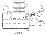
- Fuel system 10 for use with a vehicle is shown in Fig. 1.
- Fuel system 10 includes a fuel tank 18, a vapor-venting system 20 coupled to fuel tank 18 and to a vapor-recovery device 19, and a fuel-transfer system 12 including a filler neck 14 and a fuel conductor 16 coupled to filler neck 14 and coupled to fuel tank 18 to intercept liquid fuel flowing through filler neck 14 into fuel tank 18.
- Filler neck 14 conducts liquid fuel 26 to fuel conductor 16 which regulates the flow of liquid fuel 26 and fuel vapor 28 between filler neck 14 and an interior region 30 of fuel tank 18 and intercepts and guides a siphon tube 32, as shown in Fig. 5, inserted into fuel conductor 16 from filler neck 14 into interior region 30 of fuel tank 18.
- Vapor venting system 20 regulates venting of fuel vapor 28 extant in a vapor space 34 in interior region 30 of fuel tank 18 to vapor-recovery device 19.
- Fuel tank 18 includes a top wall 40, a bottom wall 42 spaced apart from top wall 40, and a side wall 44 including an inlet aperture 46 as shown in Fig. 1.
- Fuel conductor 16 is mounted to side wall 44 and arranged to extend or be extended through inlet aperture 46 as shown in Fig. 1.
- Filler neck 14 includes a mouth 48 at an outer end and a discharge outlet 50 at an inner end.
- Fuel conductor 16 has an outer end 54 coupled to discharge outlet 50 of filler neck 14 and an inner end 52 arranged to extend into interior region 30 of fuel tank 18.
- Mouth 48 is formed to receive a fuel-dispensing pump nozzle 27 during tank refueling and a closure 56 at all times other than refueling.
- Fuel conductor 16 functions, for example, to divert the flow of liquid fuel 26 into fuel tank 18 from filler neck 14 to establish a barrier configured to block flow of liquid fuel and fuel vapor between filler neck 14 and fuel tank 18 at certain times, to vent pressurized fuel vapor 28 from vapor space 34 of fuel tank 18 when necessary, and to intercept and guide siphon tube 32 from filler neck 14 toward bottom wall 42 of fuel tank 18 when it is necessary to remove liquid fuel from fuel tank 18 using siphon tube 32.
- fuel conductor 16 moves from a closed position, as shown in Fig. 2, to an opened position, as shown in Fig. 3, and diverts liquid fuel 26 dispensed into filler neck 14 into interior region 30 of fuel tank 18. After refueling, fuel conductor 16 moves back to the closed position shown in Fig. 2.
- fuel conductor 16 While fuel conductor 16 is in the closed position and fuel vapor 28 in vapor space 34 of fuel tank 18 is below a predetermined pressure level, fuel conductor 16 is also in a non-venting position and fuel conductor 16 establishes a liquid fuel and fuel vapor flow barrier between fuel tank 18 and filler neck 14 to prevent liquid fuel 26 and fuel vapor 28 from passing between filler neck 14 and fuel tank 18. If the fuel vapor pressure in vapor space 34 of fuel tank 18 is equal to or greater than the predetermined pressure level, fuel conductor 16 moves to a venting position and vents fuel vapor 28 from fuel tank 18 to filler neck 14 as shown in Fig. 4. When the pressure of fuel vapor 28 in vapor space 34 drops below the predetermined pressure level, fuel conductor 16 moves back to the non-venting position as shown in Fig. 3.
- siphon tube 32 can be inserted into fuel tank 18 and used to siphon or otherwise pump liquid fuel 26 from fuel tank 18 as shown in Fig. 5. Because liquid fuel 26 collects near bottom wall 42 of fuel tank 18, more liquid fuel 26 can be removed from fuel tank 18 if an inlet end of siphon tube 32 can be positioned to lie adjacent to bottom wall 42 of fuel tank 18.
- Fuel conductor 16 is shown diagrammatically in Figs. 2-5. Fuel conductor 16 diverts and guides siphon tube 32 as tube 32 is moved through filler neck 14 toward and into fuel tank 18. Fuel conductor 16 diverts siphon tube 32 toward bottom wall 42 of fuel tank 18 as it is being introduced into the interior region 30 of fuel tank 18 as shown in Fig. 5. When siphon tube 32 is inserted fully into fuel tank 18, the inlet end of siphon tube 32 is positioned to lie adjacent to bottom wall 42 of fuel tank 18 to enable more liquid fuel 26 to be removed from fuel tank 18.
- Fuel conductor 16 includes a housing 88 formed to include a transfer channel 150 and an aperture 166. Fuel conductor 16 further includes a diverter valve 76 positioned to lie in transfer channel 150. Diverter valve 76 regulates and guides the flow of liquid fuel 26 and fuel vapor 28 through transfer channel 150 and intercepts and guides siphon tube 32 inserted from filler neck 14 into interior region 30 of fuel tank 18.
- Diverter valve 76 includes a valve member 112 that is configured to substantially block transfer channel 150 while in a closed position when fuel is not being dispensed into filler neck 14 as shown in Fig. 2. However, during refueling, liquid fuel 26 introduced to filler neck 14 by a fuel-dispensing nozzle 27 enters housing 88 to move valve member 112 to an opened position as shown in Fig. 3. Valve member 112 intercepts and guides liquid fuel 26 from transfer channel 150 through aperture 166 into fuel tank 18. Thus, while in the opened position, valve member 112 guides liquid fuel 26 toward and through aperture 166 into fuel tank 18.
- Diverter valve 76 also includes a pressure-relief valve 82 that is configured to substantially block transfer channel 150 while in the non-venting position, as shown in Fig. 2, and to vent fuel vapor 28 from fuel tank 18 to filler neck 14 while in the venting position as shown in Fig. 4. While fuel system 10 is not being refueled, pressures within vapor space 34 of fuel tank 18 should be maintained within a certain pressure range. Thus, when fuel vapor 28 within vapor space 34 reaches a predetermined pressure level, fuel vapor 28 should be released from vapor space 34.
- pressure-relief valve 82 moves to the venting position to relieve pressure in vapor space 34 of fuel tank 18 into filler neck 14 as shown in Fig. 4.
- pressure-relief valve 82 returns to the non-venting position as shown in Fig. 2.
- Valve member 112 also intercepts and guides siphon tube 32 from filler neck 14 through fuel conductor 16 into fuel tank 18. Valve member 112 is adapted to divert a lead end 79 of siphon tube 32 from transfer channel 150 through aperture 166 into fuel tank 18 toward bottom wall 42 of fuel tank 18 as shown in Fig. 5. Housing 88 includes a top surface 89 and a bottom surface 91 facing toward bottom wall 42 of fuel tank 18. Aperture 166 is positioned in bottom surface 91 of housing 88 to direct siphon tube 32 toward bottom wall 42 of fuel tank 18. Thus, as lead end 79 of siphon tube 32 is inserted into filler neck 14 and fed through housing 88, valve member 112 intercepts and guides lead end 79 toward and through aperture 166.
- siphon tube 32 When lead end 79 of siphon tube 32 exits aperture 166, it continues to be directed toward bottom wall 42 of fuel tank 18 by valve member 112. Thus, as siphon tube 32 is fed further into filler neck 14, lead end 79 moves toward bottom wall 42 of fuel tank 18. As siphon tube 32 is continuously fed, lead end 79 is positioned to lie substantially adjacent bottom wall 42 of fuel tank 18 as shown in Fig. 5. Thus, a mechanic or other person can siphon the bulk of liquid fuel 26 from fuel tank 18 because lead end 79 of siphon tube 32 is positioned to lie substantially adjacent bottom wall 42 of fuel tank 18.
- housing 88 is elongated, sleeve-like, and made of plastics material as shown in Fig. 6a.
- Housing 88 includes an inner housing member 90 having an outer end 92 and an inner end 94 spaced apart from outer end 92, a mounting member 96, and a retainer member 98.
- Mounting member 96 is coupled around outer end 92 of inner housing member 90 and retainer member 98 is coupled inside inner end 94 of inner housing member 90 as shown in Fig. 7.
- Housing 88 is illustratively installed in fuel tank inlet aperture 46, as shown in Fig.
- inner end 94 of inner housing member 90 extends through inlet aperture 46 into fuel tank 18 and outer end 92 of inner housing member 90 extends out of fuel tank 18.
- Mounting member 96 engages and surrounds fuel inlet aperture 46 and mounts the remainder of housing 88 to fuel tank 18.
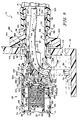
- diverter valve 76 is positioned to lie within housing 88 and includes valve member 112 and is slidable between a channel-closing position shown in Fig. 7 and a channel-opening position as shown in Fig. 8. Diverter valve 76 further includes a ramped valve seat 114 defined by inner housing member 90, and a spring 116 arranged to act against retainer member 98 of housing 88 and yieldably urge valve member 112 into engagement with ramped valve seat 114 of inner housing member 90.
- Mounting member 96 functions to mount inner housing member 90 in a rigid fixed position to filler neck 14 and fuel tank 18.
- Mounting member 96 includes a mounting sleeve 118 and a mounting flange 120.
- Mounting sleeve 118 is press-fit onto outer end 92 of inner housing member 90 and press-fit within filler neck 14 as shown in Fig. 7.
- Mounting flange 120 is appended to mounting sleeve 118 and couples the remainder of housing 88 to fuel tank 18 by hot-plate welding mounting flange 120 to fuel tank 18 as shown in Fig. 7.
- Mounting sleeve 118 includes a ramped collar 122 for securing mounting sleeve 118 within filler neck 14 and another collar 124 for abutting with an end 126 of filler neck 14 as shown in Fig. 7.
- Mounting sleeve 118 also includes an inner surface 128 having a first portion 130 spaced apart from a central axis 132 by a first distance 134, a second portion 136 spaced apart from central axis 132 by a second distance 138 that is greater than first distance 134, and an annular rim 140 therebetween. Second portion 136 defines a detent-receiving groove 142.
- Mounting flange 120 includes first, second, and third inner rims 144, 146, 148. First inner rim 144 is hot-plate welded to fuel tank 18.
- Inner housing member 90 defines transfer channel 150 for the delivery of liquid fuel 26 through inner housing member 90.
- Inner housing member 90 includes a first portion 152 that is positioned to lie in mounting member 96, a second portion 154 positioned to lie in fuel tank 18, a first side 153, and a second side 155 spaced apart from first side 153.
- First portion 152 includes a rim 156 and an outer surface 158 having a plurality of annular ridges 160, an annular detent 162, and a collar 164.
- first portion 152 is press-fit into mounting member 96, rim 156 abuts annular rim 140 of mounting member 96, annular ridges 160 grip and seal with inner surface 128 of mounting member 96, annular detent 162 mates with detent-receiving groove 142 of mounting sleeve 118, and collar 164 abuts second and third inner rims 146, 148 of flange 120 as shown in Fig. 7.
- inner housing member 90 is mounted to and substantially sealed with mounting member 96.
- Second portion 154 of inner housing member 90 includes aperture 166 of housing 88, snap-rims 168 defining a plurality of snap-receiving openings 170, ramped valve seat 114, a valve-receiving opening 171, an inside diameter 172, and a pair of alignment fins 174.
- aperture 166 cooperates with transfer channel 150 to define a fuel passageway 176 for the transfer of liquid fuel 26 and siphon tube 32 between housing 88 and fuel tank 18 as shown in Figs. 8 and 9.
- Retainer member 98 retains spring 116 within second portion 154 of inner housing member 90 and permits liquid fuel 26 and fuel vapor 28 to travel through inner end 94 of inner housing member 90.
- Retainer member 98 includes a spring seat 178, a plurality of snap-fingers 180, a plurality of alignment lugs 182, and a plurality of apertures 184.
- Valve member 112 is inserted into inner housing member 90 through valve-receiving opening 171. Next, spring 116 is inserted behind valve member 112.
- Retainer member 98 is then positioned to lie in valve-receiving opening 171 so that alignment lugs 182 are positioned to lie within second portion 154 of inner housing member 90, snap-fingers 180 engage snap-rims 168 to couple retainer member 98 to inner housing member 90, and spring 116 is positioned over spring seat 178 as shown in Fig. 7.
- valve member 112 is movable between the channel-closing position shown in Fig. 7 and the channel-opening position shown in Fig. 8.
- Valve member 112 includes a guide member 186, pressure-relief valve 82 mounted to guide member 186, a shuttle member 190 coupled to guide member 186, and a seal 192 positioned to lie between guide member 186 and shuttle member 190.
- Spring 116 abuts shuttle member 190 and biases valve member 112 to the channel-closing position as shown in Fig. 7.
- siphon tube 32 When siphon tube 32 is inserted through filler neck 14 into housing 88 in direction 194, siphon tube 32 engages guide member 186 and moves valve member 112 to the channel-opening position as shown in Fig. 9.
- Guide member 186 diverts lead end 79 of siphon tube 32 from motion in direction 194 to motion in direction 196 through aperture 166 into fuel tank 18 toward bottom wall 42.
- guide member 186 intercepts the flow of liquid fuel 26 through transfer channel 150 and guides the flow of liquid fuel 26 toward aperture 166 and supports pressure-relief valve 82.
- guide member 186 intercepts lead end 79 of siphon tube 32 and guides it toward bottom wall 42 of fuel tank 18.
- Guide member 186 includes a base 198, a scoop-shaped guide 210 having a guide surface 212, curved side walls 214, and a beveled lead edge 216, a spring seat 218, two openings 220 formed in base 198 acting as outlets, a valve chamber 199 formed in base 198, a plurality of snap-fingers 222, and a collar 224 having an aperture 226 acting as an inlet as shown in Figs. 6a-6c.
- Guide 210 is coupled to base 198 and intercepts and guides liquid fuel 26 and lead end 79 of siphon tube 32 into fuel tank 18.
- Guide surface 212 is serpentine shaped and non-orthogonal to central axis 132.
- Guide surface includes a first end 225 positioned to lie adjacent to first side 153 of inner housing member 90 and a second end 227 positioned to lie adjacent to second side 155 of inner housing member 90 and spaced apart along central axis 132 from first end 225 by a distance 229 as shown in Fig. 10.
- Guide surface 212 diverts the flow of liquid fuel and lead end 79 of siphon tube 32 from movement in direction 194 to direction 196.
- Guide surface 212 defines a guide axis 213 that cooperates with central axis 132 to define an included angle 215 that is less than ninety (90) degrees. Because liquid fuel 26 and lead end 79 of siphon tube 32 travel substantially parallel to central axis 132 before striking guide surface 212, guide surface 212 diverts the flow of liquid fuel 26 and lead end 79 of siphon tube 32 without engaging guide surface 212 at a right angle. This diversion provides a smooth transition from transfer channel 150 to aperture 166 which substantially prevents lead end 79 of siphon tube 32 from becoming "snagged" while moving through housing 88 toward bottom wall 42 of fuel tank 18.
- Guide surface 212 includes first and second curved portions 228, 230 for providing the smooth transition from transfer channel 150 to aperture 166 as discussed above.
- First curved portion 228 "scoops" the flow of liquid fuel 26 and movement of lead end 79 of siphon tube 32 from motion in direction 194 and diverts the flow and movement to direction 196.
- Second curved portion 230 continues the transition and guides the flow of liquid fuel 26 and movement of lead end 79 of siphon tube 32 away from second side 155 of housing member 90 located on second portion 154 as shown in Figs. 8 and 9.
- Second curved portion 230 also detours siphon tube 32 away from pressure-relief valve 82 during retraction of siphon tube 32 to prevent catching of siphon tube 32 during removal.
- Seal 192 substantially blocks the flow of vapor and fuel through transfer channel 150 from fuel tank 18 while valve member 112 is in the channel-closing position as shown in Fig. 7. This blocking substantially prevents liquid fuel 26 and fuel vapor 28 from moving from fuel tank 18 to transfer channel 150. However, when valve member 112 is in the channel-opening position as shown in Fig. 8, seal 192 does not substantially block transfer channel 150 from fuel tank 18 and enables liquid fuel 26 and fuel vapor 28 to travel between filler neck 14 and fuel tank 18.
- seal 192 is coupled between guide member 186 and shuttle member 190.
- Seal 192 is disk-shaped, made of flexible fluorocarbon elastomer, and includes a body portion 232, a flexible portion 234 coupled to body portion 232, and a circular rib 236 coupled to flexible portion 234.
- Body portion 232 includes a valve seat 238, an aperture 240, and a plurality of snap-receiving openings 242.
- Flexible portion 234 is resilient and permits circular rib 236 to wipe up ramped valve seat 114 as valve member 112 moves from the channel-opening position to the channel-closing position to substantially block transfer channel 150 from fuel tank 18.
- Shuttle member 190 guides the movements of valve member 112 within housing 88.
- shuttle member 190 is cup-shaped and includes a base portion 244, a cylindrical wall 246 having an outside diameter 248 and a plurality of fin-receiving grooves 250, an aperture 252, and a plurality of snap rims 254 defining a plurality of snap-receiving openings 256.
- Shuttle member 190 and seal 192 are coupled to guide member 186 by first placing seal 192 over snap-fingers 222 of guide member 186 so that snap-fingers 222 extend through snap-receiving openings 242 of seal 192. Similarly, shuttle member 190 is placed over snap-fingers 222 of guide member 186 so that snap-fingers 222 extend through snap-receiving openings 256 of shuttle member 190 and engage and lock with snap rims 254 as shown in Fig. 7. Snap-fingers 222 also act as a spring seat for spring 116 and hold spring 116 in position as shown in Fig. 7.
- Outside diameter 248 of shuttle member 190 is slightly less than inside diameter 172 of second portion 154 of inner housing member 90. This allows shuttle member 190 to slide in second portion 154 of inner housing member 90 while valve member 112 moves between the channel-opening and channel-closing positions. Furthermore, alignment fins 174 of inner housing member 90 ride in fin-receiving grooves 250 of shuttle member 190. This relationship aligns shuttle member 190 and the remainder of valve member 112 so that guide member 186 guides liquid fuel 26 and siphon tube 32 toward aperture 166. Thus, shuttle member 190 guides the remainder of valve member 112 during movement from the channel-closing position, as shown in Fig. 7, to the channel-closing position as shown in Fig. 8
- Pressure-relief valve 82 is positioned to lie in valve chamber 199 and regulates the flow of fuel vapor between fuel tank 18 and filler neck 14.
- pressure-relief valve 82 moves from a non-venting position, as shown in Fig. 7, to a venting position as shown in Fig. 10.
- Pressure-relief valve 82 includes a valve member 258, valve seat 238, and a spring 260 positioned to lie over spring seat 218 of guide member 186 between valve member 258. Spring 260 biases valve member 258 in direction 194 to the non-venting position against valve seat 238 of body portion 232 of seal 192.
- valve member 258 when fuel tank 18 is at a pressure level lower than the predetermined level, valve member 258 remains in the non-venting position and engages valve seat 238 to substantially block fuel tank 18 from transfer channel 150 and filler neck 14 when valve member 112 is in the channel-closing position as shown in Fig. 7.
- valve member 258 moves away from valve seat 238 to the venting position against the bias provided by spring 260 as shown in Fig. 10.
- fuel vapor 28 will vent from fuel tank 18 through transfer channel 150 to filler neck 14.
- valve 82 When pressure-relief valve 82 is in the venting position, fuel vapor 28 travels from to fuel tank 18 to transfer channel 150 to filler neck 14 through shuttle member 190, seal 192, and guide member 186. Fuel vapor 28 enters housing 88 from fuel tank 18 through aperture 166 of inner housing member 90 and apertures 184 in retainer member 98. While in the venting position, fuel vapor 28 flows through respective apertures 252, 240, 226, of shuttle member 190, seal 192, and guide member 186, through openings 220 of guide member 186, and past guide 210 into transfer channel 150 and filler neck 14. Base 198 of valve member 112 and housing 88 define a movable chamber 259 into which openings 220 dump fuel vapor during venting. According to an alternative embodiment of the present invention, the diverter valve does not include a pressure-relief valve.
- Mounting member 96 is made of electrically conductive HDPE (high density polyethylene) and inner housing member 90 is made of electrically conductive acetal. Because mounting member 96 and inner housing member 90 are made of electrically conductive material, housing 88 is electrically conductive. Because housing 88 is mounted between fuel tank 16 and filler neck 14 and is conductive, housing 88 provides an electrical path between fuel tank 16 and filler neck 14. Thus, static charge that develops in fuel tank 16 can pass through housing 88 to filler neck 14 and the vehicle body (not shown). Thus, a conductive path between fuel tank 16 and the vehicle body has been provided by housing 88 and filler neck 16.
- HDPE high density polyethylene
- Guide member 386 includes a body portion 398, a scoop-shaped guide 310 having a guide surface 312, curved side walls 314, and a beveled lead edge 316, a spring seat 318, four ribs 321 defining four openings 320 in body portion 398, a first pair of snap-fingers 322, a second pair of snap-fingers 323, and a collar 324 having an aperture 326.
- First pair of snap fingers 322 have a width 328 and second pair of snap fingers 323 have a width 330 that is greater than width 328 of first pair of snap fingers 322.
- Guide member 386 functions in a manner similar to guide member 186.
- Shuttle member 390 mates with guide member 386 and is shown in Figs. 11c and 11d.
- Shuttle member 390 is cup-shaped and includes a base portion 344, a cylindrical wall 346 having a plurality of fin-receiving grooves 350, an aperture 352, a first pair of snap rims 354 defining a first pair of snap-receiving openings 356, and a second pair of snap rims 355 defining a second pair of snap-receiving openings 357.
- First pair of snap-receiving openings 356 are sized and shaped to receive first pair of snap-fingers 322 and second pair of snap-receiving openings 357 are sized and shaped to receive second pair of snap fingers 323.
- Shuttle member 390 functions in a manner similar to shuttle member 190.
- Snap fingers 322, 323 and snap-receiving openings 356, 357 are "indexed” to aid in aligning guide member 386 with shuttle member 390 during assembly.
- Second pair of snap fingers 323 are sized to be larger than first pair of snap-receiving openings 356 so that only first pair of snap fingers 323 will fit within first pair of snap-receiving openings 356. This indexing helps insure that fin-receiving grooves 350 will align properly with scoop-shaped guide 310 during assembly of shuttle member 390, seal 192, and guide member 386.
Landscapes
- Engineering & Computer Science (AREA)
- Life Sciences & Earth Sciences (AREA)
- Sustainable Development (AREA)
- Sustainable Energy (AREA)
- Chemical & Material Sciences (AREA)
- Combustion & Propulsion (AREA)
- Transportation (AREA)
- Mechanical Engineering (AREA)
- Cooling, Air Intake And Gas Exhaust, And Fuel Tank Arrangements In Propulsion Units (AREA)
Abstract
Description
- This invention relates to a fuel system, and particularly to a fuel-transfer system. More particularly, this invention relates to a vehicle filler neck and a valve for regulating flow of liquid fuel and fuel vapor between the vehicle filler neck and a vehicle fuel tank.
- A filler neck is a tube which conducts liquid fuel from a fuel-dispensing pump nozzle to an interior fuel-storage region in a fuel tank. Although an opened passageway through the filler neck into the fuel tank is needed during refueling to conduct liquid fuel from the pump nozzle into the fuel tank, it is desirable to close the filler neck at other times to block discharge of liquid fuel and fuel vapor from the fuel tank through the filler neck. However, if the pressure of fuel vapor in the fuel tank reaches a predetermined level, it is desirable to relieve the pressure in the fuel tank by venting pressurized fuel vapor from the fuel tank to the filler neck for discharge therefrom.
- On occasion, it is necessary for mechanics to remove liquid fuel from the fuel tank during maintenance or repair of a vehicle. To remove the liquid fuel, a mechanic or other individual often inserts a siphon tube through the filler neck into the fuel tank and siphons or otherwise pumps the liquid fuel from the fuel tank.
- According to the present invention, a fuel-transfer system includes a fuel tank and a fuel conductor coupled to the fuel tank. The fuel conductor includes a housing having a fuel-transfer channel and a diverter valve positioned to lie in the fuel-transfer channel. The diverter valve is movable from a first position blocking the flow of fuel vapor or liquid fuel through the channel to a second position permitting the flow of fuel vapor or liquid fuel through the channel. The diverter valve includes a guide surface adapted to intercept and divert a siphon tube moving in a fuel tank filler neck and guide it toward a bottom wall of the fuel tank.
- In preferred embodiments, the diverter valve further includes a pressure-relief valve. The pressure-relief valve is movable between a first position blocking the flow of fuel vapor through the diverter valve to a second position permitting the flow of fuel vapor through the diverter valve and the fuel-transfer system. The pressure-relief valve moves to the second position when fuel vapor pressure levels in the fuel tank reach a predetermined level to relieve pressure in the fuel tank.
- Additional features of the invention will become apparent to those skilled in the art upon consideration of the following detailed description of preferred embodiments exemplifying the best mode of carrying out the invention as presently perceived.
- The detailed description particularly refers to the accompanying figures in which:
- Fig. 1 is a diagrammatic view of a vehicle fuel system having a vapor venting system and a fuel-transfer system including a filler neck, a fuel conductor in accordance with the present invention, and a fuel tank, the fuel conductor being positioned in the fuel tank and filler neck to regulate the transfer of liquid fuel and fuel vapor between the fuel tank and the filler neck;
- Fig. 2 is a diagrammatic view of a fuel-transfer system in accordance with the present invention showing a fuel conductor including a housing and a diverter valve (in phantom), the diverter valve including a valve member and a pressure-relief valve and being positioned to lie in the housing, the valve member being moved to a closed position substantially blocking the filler neck from the fuel tank, and the pressure-relief valve being in a non-venting position substantially blocking the filler neck from the fuel tank;
- Fig. 3 is a view similar to Fig. 2 showing the valve member after it has been moved to an opened position during tank refueling so that liquid fuel is diverted into the fuel tank;
- Fig. 4 is a view similar to Fig. 2 showing the valve member moved to the closed position and the pressure-relief valve moved to a venting position due to fuel vapor pressure in the fuel tank being at a level equal to or greater than a predetermined level so that pressurized fuel vapor can be vented through the filler neck to the atmosphere through a vent system provided in a closure mounted on the outlet end of the filler neck;
- Fig. 5 is a view similar to Fig. 2 showing the valve member moved to the opened position while a siphon tube is inserted through the now-opened filler neck (i.e., the closure has been removed) and housing into the fuel tank and showing the valve member engaging the siphon tube and directing it toward a bottom wall of the fuel tank so that liquid fuel can be removed by a mechanic or other individual using the siphon tube;
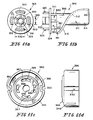
- Fig. 6a is a perspective assembly view of an embodiment of the fuel conductor including a housing (shown in the dashed boxes) and a diverter valve (shown in the largest bracket), the housing including a mounting member (shown in the upper left-hand dashed box) adapted to be coupled to the filler neck, an inner housing member (shown in the upper right-hand dashed box) arranged to be coupled to the mounting member, and a retainer member (shown in the lower left-hand dashed box) arranged to be coupled to the inner housing member to capture the diverter valve within the inner housing member, the diverter valve including a valve member (shown in the intermediate bracket) and a spring, the inner housing member including a fuel-transfer channel and a fuel-transfer aperture and the valve member including a scoop-shaped guide member, a disk-shaped seal, a cup-shaped shuttle member, and a pressure-relief valve (shown in the smallest bracket);
- Fig. 6b is an end elevation view of the scoop-shaped guide member of
Fig. 6a taken along
line 6b-6b of Fig. 6c; - Fig. 6c is a side elevation view of the guide member of Figs. 6a and 6b
taken along
line 6c-6c of Fig. 6b showing a central body portion, three of the four snap fingers coupled to the left end of the central body portion, and a scoop-shaped guide coupled to the right end of the central body portion and configured to guide a siphon tube passing through the housing into a fuel tank as shown in Fig. 9; - Fig. 6d is an end elevation view of the shuttle member of Fig. 6a taken along line 6d-6d of Fig. 6e showing the shuttle member formed to include four snap-receiving openings sized to receive the four snap fingers of the guide member;
- Fig. 6e is a side elevation view of the shuttle member of Figs. 6a and 6d
taken along
line 6e-6e of Fig. 6d; - Fig. 7 is a cross-sectional view of the fuel tank, fuel conductor, and filler neck of Fig. 1 showing the diverter valve in a channel-closing position to block flow of liquid fuel and fuel vapor between the fuel tank and the filler neck;
- Fig. 8 is a cross-section view similar to Fig. 7 showing the diverter valve after it has been moved to a channel-opening position by a stream of liquid fuel passing through the filler neck during refueling and showing the scoop-shaped guide member intercepting and guiding the stream of liquid fuel passing from the filer neck through the fuel-transfer aperture into the fuel tank;
- Fig. 9 is a cross-sectional view similar to Fig. 7 showing the lead end of the siphon tube fully inserted through the fuel conductor, the scoop-shaped guide member of the valve member having intercepted the lead end of the siphon tube and having directed it to lie substantially adjacent to the bottom wall of the fuel tank as the siphon tube was passed down through the filler neck and the fuel conductor into the fuel tank, and the siphon tube functioning to remove liquid fuel from the fuel tank;
- Fig. 10 is an enlarged cross-sectional view similar to Fig. 7 showing the pressure-relief valve in a venting position while the fuel vapor in the fuel tank is at a pressure level equal to or greater than a predetermined pressure level so that pressurized fuel vapor is discharged from the fuel tank through the filler neck;
- Figs. 11a-11d show another embodiment of the scoop-shaped guide member and shuttle member illustrated in Figs. 6a-6e;
- Fig. 11a is an end elevation view of a guide member including a pair of snap fingers having a first size and another pair of snap fingers having a larger second size;
- Fig. 11b is a side elevation view of the guide member of Fig. 11a showing the guide member including the first pair of small size snap fingers and one of the second pair of large size snap fingers;
- Fig. 11c is an end elevation view of a shuttle member configured to mate with the guide member of Figs. 11a and 11b and formed to include a first pair of small snap-receiving openings sized to receive the first pair of small size snap fingers of the guide member of Fig. 11a and a second pair of large snap-receiving openings sized to receive the second pair of large size snap fingers; and
- Fig. 11d is a side elevation view of the shuttle member of Fig. 11c.
-
- A
fuel system 10 for use with a vehicle is shown in Fig. 1.Fuel system 10 includes afuel tank 18, a vapor-venting system 20 coupled tofuel tank 18 and to a vapor-recovery device 19, and a fuel-transfer system 12 including afiller neck 14 and afuel conductor 16 coupled tofiller neck 14 and coupled tofuel tank 18 to intercept liquid fuel flowing throughfiller neck 14 intofuel tank 18.Filler neck 14 conductsliquid fuel 26 tofuel conductor 16 which regulates the flow ofliquid fuel 26 andfuel vapor 28 betweenfiller neck 14 and aninterior region 30 offuel tank 18 and intercepts and guides asiphon tube 32, as shown in Fig. 5, inserted intofuel conductor 16 fromfiller neck 14 intointerior region 30 offuel tank 18.Vapor venting system 20 regulates venting offuel vapor 28 extant in avapor space 34 ininterior region 30 offuel tank 18 to vapor-recovery device 19. -
Fuel tank 18 includes atop wall 40, abottom wall 42 spaced apart fromtop wall 40, and aside wall 44 including aninlet aperture 46 as shown in Fig. 1.Fuel conductor 16 is mounted toside wall 44 and arranged to extend or be extended throughinlet aperture 46 as shown in Fig. 1.Filler neck 14 includes amouth 48 at an outer end and adischarge outlet 50 at an inner end.Fuel conductor 16 has anouter end 54 coupled to dischargeoutlet 50 offiller neck 14 and aninner end 52 arranged to extend intointerior region 30 offuel tank 18.Mouth 48 is formed to receive a fuel-dispensingpump nozzle 27 during tank refueling and aclosure 56 at all times other than refueling. -
Fuel conductor 16 functions, for example, to divert the flow ofliquid fuel 26 intofuel tank 18 fromfiller neck 14 to establish a barrier configured to block flow of liquid fuel and fuel vapor betweenfiller neck 14 andfuel tank 18 at certain times, to ventpressurized fuel vapor 28 fromvapor space 34 offuel tank 18 when necessary, and to intercept and guide siphontube 32 fromfiller neck 14 towardbottom wall 42 offuel tank 18 when it is necessary to remove liquid fuel fromfuel tank 18 using siphontube 32. During refueling,fuel conductor 16 moves from a closed position, as shown in Fig. 2, to an opened position, as shown in Fig. 3, and divertsliquid fuel 26 dispensed intofiller neck 14 intointerior region 30 offuel tank 18. After refueling,fuel conductor 16 moves back to the closed position shown in Fig. 2. - While
fuel conductor 16 is in the closed position andfuel vapor 28 invapor space 34 offuel tank 18 is below a predetermined pressure level,fuel conductor 16 is also in a non-venting position andfuel conductor 16 establishes a liquid fuel and fuel vapor flow barrier betweenfuel tank 18 andfiller neck 14 to preventliquid fuel 26 andfuel vapor 28 from passing betweenfiller neck 14 andfuel tank 18. If the fuel vapor pressure invapor space 34 offuel tank 18 is equal to or greater than the predetermined pressure level,fuel conductor 16 moves to a venting position and ventsfuel vapor 28 fromfuel tank 18 tofiller neck 14 as shown in Fig. 4. When the pressure offuel vapor 28 invapor space 34 drops below the predetermined pressure level,fuel conductor 16 moves back to the non-venting position as shown in Fig. 3. - On occasion, it is necessary or convenient to remove
liquid fuel 26 fromfuel tank 18. To this end, siphontube 32 can be inserted intofuel tank 18 and used to siphon or otherwise pumpliquid fuel 26 fromfuel tank 18 as shown in Fig. 5. Becauseliquid fuel 26 collects nearbottom wall 42 offuel tank 18, moreliquid fuel 26 can be removed fromfuel tank 18 if an inlet end of siphontube 32 can be positioned to lie adjacent tobottom wall 42 offuel tank 18. -
Fuel conductor 16 is shown diagrammatically in Figs. 2-5.Fuel conductor 16 diverts and guides siphontube 32 astube 32 is moved throughfiller neck 14 toward and intofuel tank 18.Fuel conductor 16 diverts siphontube 32 towardbottom wall 42 offuel tank 18 as it is being introduced into theinterior region 30 offuel tank 18 as shown in Fig. 5. When siphontube 32 is inserted fully intofuel tank 18, the inlet end of siphontube 32 is positioned to lie adjacent tobottom wall 42 offuel tank 18 to enable moreliquid fuel 26 to be removed fromfuel tank 18. -
Fuel conductor 16 includes ahousing 88 formed to include atransfer channel 150 and anaperture 166.Fuel conductor 16 further includes adiverter valve 76 positioned to lie intransfer channel 150.Diverter valve 76 regulates and guides the flow ofliquid fuel 26 andfuel vapor 28 throughtransfer channel 150 and intercepts and guides siphontube 32 inserted fromfiller neck 14 intointerior region 30 offuel tank 18. -
Diverter valve 76 includes avalve member 112 that is configured to substantially blocktransfer channel 150 while in a closed position when fuel is not being dispensed intofiller neck 14 as shown in Fig. 2. However, during refueling,liquid fuel 26 introduced tofiller neck 14 by a fuel-dispensingnozzle 27 entershousing 88 to movevalve member 112 to an opened position as shown in Fig. 3.Valve member 112 intercepts and guidesliquid fuel 26 fromtransfer channel 150 throughaperture 166 intofuel tank 18. Thus, while in the opened position,valve member 112 guidesliquid fuel 26 toward and throughaperture 166 intofuel tank 18. -
Diverter valve 76 also includes a pressure-relief valve 82 that is configured to substantially blocktransfer channel 150 while in the non-venting position, as shown in Fig. 2, and to ventfuel vapor 28 fromfuel tank 18 tofiller neck 14 while in the venting position as shown in Fig. 4. Whilefuel system 10 is not being refueled, pressures withinvapor space 34 offuel tank 18 should be maintained within a certain pressure range. Thus, whenfuel vapor 28 withinvapor space 34 reaches a predetermined pressure level,fuel vapor 28 should be released fromvapor space 34. Therefore, whenfuel vapor 28 invapor space 34 reaches the predetermined pressure level, pressure-relief valve 82 moves to the venting position to relieve pressure invapor space 34 offuel tank 18 intofiller neck 14 as shown in Fig. 4. Whenenough fuel vapor 28 is released fromfuel tank 18 to release pressure below the predetermined level, pressure-relief valve 82 returns to the non-venting position as shown in Fig. 2. -
Valve member 112 also intercepts and guides siphontube 32 fromfiller neck 14 throughfuel conductor 16 intofuel tank 18.Valve member 112 is adapted to divert alead end 79 of siphontube 32 fromtransfer channel 150 throughaperture 166 intofuel tank 18 towardbottom wall 42 offuel tank 18 as shown in Fig. 5.Housing 88 includes atop surface 89 and abottom surface 91 facing towardbottom wall 42 offuel tank 18.Aperture 166 is positioned inbottom surface 91 ofhousing 88 to direct siphontube 32 towardbottom wall 42 offuel tank 18. Thus, aslead end 79 of siphontube 32 is inserted intofiller neck 14 and fed throughhousing 88,valve member 112 intercepts and guideslead end 79 toward and throughaperture 166. - When
lead end 79 of siphontube 32exits aperture 166, it continues to be directed towardbottom wall 42 offuel tank 18 byvalve member 112. Thus, as siphontube 32 is fed further intofiller neck 14,lead end 79 moves towardbottom wall 42 offuel tank 18. As siphontube 32 is continuously fed,lead end 79 is positioned to lie substantially adjacentbottom wall 42 offuel tank 18 as shown in Fig. 5. Thus, a mechanic or other person can siphon the bulk ofliquid fuel 26 fromfuel tank 18 becauselead end 79 of siphontube 32 is positioned to lie substantially adjacentbottom wall 42 offuel tank 18. - In an illustrative embodiment,
housing 88 is elongated, sleeve-like, and made of plastics material as shown in Fig. 6a.Housing 88 includes aninner housing member 90 having anouter end 92 and aninner end 94 spaced apart fromouter end 92, a mountingmember 96, and aretainer member 98. Mountingmember 96 is coupled aroundouter end 92 ofinner housing member 90 andretainer member 98 is coupled insideinner end 94 ofinner housing member 90 as shown in Fig. 7.Housing 88 is illustratively installed in fueltank inlet aperture 46, as shown in Fig. 7, so thatinner end 94 ofinner housing member 90 extends throughinlet aperture 46 intofuel tank 18 andouter end 92 ofinner housing member 90 extends out offuel tank 18. Mountingmember 96 engages and surroundsfuel inlet aperture 46 and mounts the remainder ofhousing 88 tofuel tank 18. - In an illustrative embodiment,
diverter valve 76 is positioned to lie withinhousing 88 and includesvalve member 112 and is slidable between a channel-closing position shown in Fig. 7 and a channel-opening position as shown in Fig. 8.Diverter valve 76 further includes a rampedvalve seat 114 defined byinner housing member 90, and aspring 116 arranged to act againstretainer member 98 ofhousing 88 and yieldably urgevalve member 112 into engagement with rampedvalve seat 114 ofinner housing member 90. - Mounting
member 96 functions to mountinner housing member 90 in a rigid fixed position tofiller neck 14 andfuel tank 18. Mountingmember 96 includes a mountingsleeve 118 and a mountingflange 120. Mountingsleeve 118 is press-fit ontoouter end 92 ofinner housing member 90 and press-fit withinfiller neck 14 as shown in Fig. 7. Mountingflange 120 is appended to mountingsleeve 118 and couples the remainder ofhousing 88 tofuel tank 18 by hot-platewelding mounting flange 120 tofuel tank 18 as shown in Fig. 7. - Mounting
sleeve 118 includes a rampedcollar 122 for securing mountingsleeve 118 withinfiller neck 14 and anothercollar 124 for abutting with anend 126 offiller neck 14 as shown in Fig. 7. Mountingsleeve 118 also includes aninner surface 128 having afirst portion 130 spaced apart from acentral axis 132 by afirst distance 134, asecond portion 136 spaced apart fromcentral axis 132 by asecond distance 138 that is greater thanfirst distance 134, and anannular rim 140 therebetween.Second portion 136 defines a detent-receivinggroove 142. Mountingflange 120 includes first, second, and thirdinner rims inner rim 144 is hot-plate welded tofuel tank 18. -
Inner housing member 90 definestransfer channel 150 for the delivery ofliquid fuel 26 throughinner housing member 90.Inner housing member 90 includes afirst portion 152 that is positioned to lie in mountingmember 96, asecond portion 154 positioned to lie infuel tank 18, afirst side 153, and asecond side 155 spaced apart fromfirst side 153.First portion 152 includes arim 156 and anouter surface 158 having a plurality ofannular ridges 160, anannular detent 162, and acollar 164. Whenfirst portion 152 is press-fit into mountingmember 96,rim 156 abutsannular rim 140 of mountingmember 96,annular ridges 160 grip and seal withinner surface 128 of mountingmember 96,annular detent 162 mates with detent-receivinggroove 142 of mountingsleeve 118, andcollar 164 abuts second and thirdinner rims flange 120 as shown in Fig. 7. Thus,inner housing member 90 is mounted to and substantially sealed with mountingmember 96. -
Second portion 154 ofinner housing member 90 includesaperture 166 ofhousing 88, snap-rims 168 defining a plurality of snap-receivingopenings 170, rampedvalve seat 114, a valve-receivingopening 171, aninside diameter 172, and a pair ofalignment fins 174. Whenvalve member 112 is in the channel-opening position,aperture 166 cooperates withtransfer channel 150 to define afuel passageway 176 for the transfer ofliquid fuel 26 and siphontube 32 betweenhousing 88 andfuel tank 18 as shown in Figs. 8 and 9. -
Retainer member 98 retainsspring 116 withinsecond portion 154 ofinner housing member 90 and permitsliquid fuel 26 andfuel vapor 28 to travel throughinner end 94 ofinner housing member 90.Retainer member 98 includes aspring seat 178, a plurality of snap-fingers 180, a plurality of alignment lugs 182, and a plurality ofapertures 184.Valve member 112 is inserted intoinner housing member 90 through valve-receivingopening 171. Next,spring 116 is inserted behindvalve member 112.Retainer member 98 is then positioned to lie in valve-receivingopening 171 so that alignment lugs 182 are positioned to lie withinsecond portion 154 ofinner housing member 90, snap-fingers 180 engage snap-rims 168 to coupleretainer member 98 toinner housing member 90, andspring 116 is positioned overspring seat 178 as shown in Fig. 7. - As previously mentioned,
valve member 112 is movable between the channel-closing position shown in Fig. 7 and the channel-opening position shown in Fig. 8.Valve member 112 includes aguide member 186, pressure-relief valve 82 mounted to guidemember 186, ashuttle member 190 coupled to guidemember 186, and aseal 192 positioned to lie betweenguide member 186 andshuttle member 190.Spring 116 abutsshuttle member 190 andbiases valve member 112 to the channel-closing position as shown in Fig. 7. Whenliquid fuel 26 entershousing 88 indirection 194 fromfiller neck 14 during refueling,liquid fuel 26 engagesguide member 186 and movesvalve member 112 to the channel-opening position against the bias provided byspring 116 as shown in Fig. 8.Guide member 186 divertsliquid fuel 26 from motion indirection 194 to motion indirection 196 throughaperture 166 intofuel tank 18. Lesser amounts ofliquid fuel 26 also exit throughapertures 184 ofretainer member 98 intofuel tank 18 as shown in Fig. 8. - When siphon
tube 32 is inserted throughfiller neck 14 intohousing 88 indirection 194, siphontube 32 engagesguide member 186 and movesvalve member 112 to the channel-opening position as shown in Fig. 9.Guide member 186 divertslead end 79 of siphontube 32 from motion indirection 194 to motion indirection 196 throughaperture 166 intofuel tank 18 towardbottom wall 42. Thus,guide member 186 intercepts the flow ofliquid fuel 26 throughtransfer channel 150 and guides the flow ofliquid fuel 26 towardaperture 166 and supports pressure-relief valve 82. Similarly,guide member 186 interceptslead end 79 of siphontube 32 and guides it towardbottom wall 42 offuel tank 18. -
Guide member 186 includes abase 198, a scoop-shapedguide 210 having aguide surface 212,curved side walls 214, and abeveled lead edge 216, aspring seat 218, twoopenings 220 formed inbase 198 acting as outlets, avalve chamber 199 formed inbase 198, a plurality of snap-fingers 222, and acollar 224 having anaperture 226 acting as an inlet as shown in Figs. 6a-6c.Guide 210 is coupled tobase 198 and intercepts and guidesliquid fuel 26 andlead end 79 of siphontube 32 intofuel tank 18. -
Guide surface 212 is serpentine shaped and non-orthogonal tocentral axis 132. Guide surface includes afirst end 225 positioned to lie adjacent tofirst side 153 ofinner housing member 90 and asecond end 227 positioned to lie adjacent tosecond side 155 ofinner housing member 90 and spaced apart alongcentral axis 132 fromfirst end 225 by adistance 229 as shown in Fig. 10. -
Guide surface 212 diverts the flow of liquid fuel andlead end 79 of siphontube 32 from movement indirection 194 todirection 196.Guide surface 212 defines aguide axis 213 that cooperates withcentral axis 132 to define an includedangle 215 that is less than ninety (90) degrees. Becauseliquid fuel 26 andlead end 79 of siphontube 32 travel substantially parallel tocentral axis 132 before strikingguide surface 212,guide surface 212 diverts the flow ofliquid fuel 26 andlead end 79 of siphontube 32 without engagingguide surface 212 at a right angle. This diversion provides a smooth transition fromtransfer channel 150 toaperture 166 which substantially preventslead end 79 of siphontube 32 from becoming "snagged" while moving throughhousing 88 towardbottom wall 42 offuel tank 18. -
Guide surface 212 includes first and secondcurved portions transfer channel 150 toaperture 166 as discussed above. Firstcurved portion 228 "scoops" the flow ofliquid fuel 26 and movement oflead end 79 of siphontube 32 from motion indirection 194 and diverts the flow and movement todirection 196. Secondcurved portion 230 continues the transition and guides the flow ofliquid fuel 26 and movement oflead end 79 of siphontube 32 away fromsecond side 155 ofhousing member 90 located onsecond portion 154 as shown in Figs. 8 and 9. Secondcurved portion 230 also detours siphontube 32 away from pressure-relief valve 82 during retraction of siphontube 32 to prevent catching of siphontube 32 during removal. -
Seal 192 substantially blocks the flow of vapor and fuel throughtransfer channel 150 fromfuel tank 18 whilevalve member 112 is in the channel-closing position as shown in Fig. 7. This blocking substantially preventsliquid fuel 26 andfuel vapor 28 from moving fromfuel tank 18 to transferchannel 150. However, whenvalve member 112 is in the channel-opening position as shown in Fig. 8,seal 192 does not substantially blocktransfer channel 150 fromfuel tank 18 and enablesliquid fuel 26 andfuel vapor 28 to travel betweenfiller neck 14 andfuel tank 18. - As shown in Fig. 7,
seal 192 is coupled betweenguide member 186 andshuttle member 190.Seal 192 is disk-shaped, made of flexible fluorocarbon elastomer, and includes abody portion 232, aflexible portion 234 coupled tobody portion 232, and acircular rib 236 coupled toflexible portion 234.Body portion 232 includes avalve seat 238, anaperture 240, and a plurality of snap-receivingopenings 242.Flexible portion 234 is resilient and permitscircular rib 236 to wipe up rampedvalve seat 114 asvalve member 112 moves from the channel-opening position to the channel-closing position to substantially blocktransfer channel 150 fromfuel tank 18. -
Shuttle member 190 guides the movements ofvalve member 112 withinhousing 88. As shown in Figs. 6a, 6d, and 6e,shuttle member 190 is cup-shaped and includes abase portion 244, acylindrical wall 246 having anoutside diameter 248 and a plurality of fin-receivinggrooves 250, anaperture 252, and a plurality ofsnap rims 254 defining a plurality of snap-receivingopenings 256. -
Shuttle member 190 and seal 192 are coupled to guidemember 186 by first placingseal 192 over snap-fingers 222 ofguide member 186 so that snap-fingers 222 extend through snap-receivingopenings 242 ofseal 192. Similarly,shuttle member 190 is placed over snap-fingers 222 ofguide member 186 so that snap-fingers 222 extend through snap-receivingopenings 256 ofshuttle member 190 and engage and lock withsnap rims 254 as shown in Fig. 7. Snap-fingers 222 also act as a spring seat forspring 116 and holdspring 116 in position as shown in Fig. 7. - Outside
diameter 248 ofshuttle member 190 is slightly less thaninside diameter 172 ofsecond portion 154 ofinner housing member 90. This allowsshuttle member 190 to slide insecond portion 154 ofinner housing member 90 whilevalve member 112 moves between the channel-opening and channel-closing positions. Furthermore,alignment fins 174 ofinner housing member 90 ride in fin-receivinggrooves 250 ofshuttle member 190. This relationship alignsshuttle member 190 and the remainder ofvalve member 112 so thatguide member 186 guidesliquid fuel 26 and siphontube 32 towardaperture 166. Thus,shuttle member 190 guides the remainder ofvalve member 112 during movement from the channel-closing position, as shown in Fig. 7, to the channel-closing position as shown in Fig. 8 - Pressure-
relief valve 82 is positioned to lie invalve chamber 199 and regulates the flow of fuel vapor betweenfuel tank 18 andfiller neck 14. Whenfuel vapor 28 infuel tank 18 reaches a predetermined pressure level (approximately 13 inches of water) pressure-relief valve 82 moves from a non-venting position, as shown in Fig. 7, to a venting position as shown in Fig. 10. Pressure-relief valve 82 includes avalve member 258,valve seat 238, and aspring 260 positioned to lie overspring seat 218 ofguide member 186 betweenvalve member 258.Spring 260biases valve member 258 indirection 194 to the non-venting position againstvalve seat 238 ofbody portion 232 ofseal 192. Thus, whenfuel tank 18 is at a pressure level lower than the predetermined level,valve member 258 remains in the non-venting position and engagesvalve seat 238 to substantially blockfuel tank 18 fromtransfer channel 150 andfiller neck 14 whenvalve member 112 is in the channel-closing position as shown in Fig. 7. - When
fuel tank 18 is at a pressure level equal to or greater than the predetermined level,valve member 258 moves away fromvalve seat 238 to the venting position against the bias provided byspring 260 as shown in Fig. 10. Thus, whenfuel tank 18 is at a pressure equal to or greater than the predetermined level andvalve member 258 is in the opened position,fuel vapor 28 will vent fromfuel tank 18 throughtransfer channel 150 tofiller neck 14. - When pressure-
relief valve 82 is in the venting position,fuel vapor 28 travels from tofuel tank 18 to transferchannel 150 tofiller neck 14 throughshuttle member 190,seal 192, and guidemember 186.Fuel vapor 28 entershousing 88 fromfuel tank 18 throughaperture 166 ofinner housing member 90 andapertures 184 inretainer member 98. While in the venting position,fuel vapor 28 flows throughrespective apertures shuttle member 190,seal 192, and guidemember 186, throughopenings 220 ofguide member 186, andpast guide 210 intotransfer channel 150 andfiller neck 14.Base 198 ofvalve member 112 andhousing 88 define amovable chamber 259 into whichopenings 220 dump fuel vapor during venting. According to an alternative embodiment of the present invention, the diverter valve does not include a pressure-relief valve. - Mounting
member 96 is made of electrically conductive HDPE (high density polyethylene) andinner housing member 90 is made of electrically conductive acetal. Because mountingmember 96 andinner housing member 90 are made of electrically conductive material,housing 88 is electrically conductive. Becausehousing 88 is mounted betweenfuel tank 16 andfiller neck 14 and is conductive,housing 88 provides an electrical path betweenfuel tank 16 andfiller neck 14. Thus, static charge that develops infuel tank 16 can pass throughhousing 88 tofiller neck 14 and the vehicle body (not shown). Thus, a conductive path betweenfuel tank 16 and the vehicle body has been provided byhousing 88 andfiller neck 16. - A presently preferred embodiment of a
guide member 386 is shown in Figs. 11a.Guide member 386 includes abody portion 398, a scoop-shapedguide 310 having aguide surface 312,curved side walls 314, and abeveled lead edge 316, aspring seat 318, fourribs 321 defining fouropenings 320 inbody portion 398, a first pair of snap-fingers 322, a second pair of snap-fingers 323, and acollar 324 having anaperture 326. First pair ofsnap fingers 322 have awidth 328 and second pair ofsnap fingers 323 have awidth 330 that is greater thanwidth 328 of first pair ofsnap fingers 322.Guide member 386 functions in a manner similar to guidemember 186. - A presently preferred embodiment of a
shuttle member 390 mates withguide member 386 and is shown in Figs. 11c and 11d.Shuttle member 390 is cup-shaped and includes abase portion 344, acylindrical wall 346 having a plurality of fin-receivinggrooves 350, anaperture 352, a first pair ofsnap rims 354 defining a first pair of snap-receivingopenings 356, and a second pair ofsnap rims 355 defining a second pair of snap-receivingopenings 357. First pair of snap-receivingopenings 356 are sized and shaped to receive first pair of snap-fingers 322 and second pair of snap-receivingopenings 357 are sized and shaped to receive second pair ofsnap fingers 323.Shuttle member 390 functions in a manner similar toshuttle member 190. -
Snap fingers openings guide member 386 withshuttle member 390 during assembly. Second pair ofsnap fingers 323 are sized to be larger than first pair of snap-receivingopenings 356 so that only first pair ofsnap fingers 323 will fit within first pair of snap-receivingopenings 356. This indexing helps insure that fin-receivinggrooves 350 will align properly with scoop-shapedguide 310 during assembly ofshuttle member 390,seal 192, and guidemember 386. - Although this invention has been described in detail with reference to certain embodiments, variations and modifications exist within the scope and spirit of the invention as described and as defined in the following claims.
Claims (15)
- A fuel-transfer system for communicating fuel into a fuel tank including a top wall and a bottom wall spaced apart from the top wall, the system comprisinga filler neck configured to receive fuel anda fuel conductor adapted to be coupled to a fuel tank and filler neck, the fuel conductor including a housing and a diverter valve, the housing being formed to include an inlet in communication with the filler neck, an outlet in communication with the fuel tank, and a transfer channel extending between the inlet and outlet, the diverter valve being positioned to lie in the transfer channel for movement along a central axis between a closed position substantially blocking the inlet from the outlet and an opened position permitting communication between the inlet and outlet through the transfer channel, the diverter valve being adapted to intercept and guide a tube moving through the filler neck into the transfer channel toward a bottom wall of the fuel tank.
- The fuel-transfer system of claim 1, wherein the diverter valve includes a base and a pressure-relief valve coupled to the base for movement between a closed position blocking the flow of fuel vapor from the fuel tank through the inlet to an opened position permitting the flow of fuel vapor from the fuel tank through the inlet.
- The fuel-transfer system of claim 2, wherein the base is formed to include an inlet, an outlet adapted to open toward a bottom wall of the fuel tank, and a valve chamber extending between the inlet and outlet of the base, the pressure-relief valve is positioned to lie in the valve chamber for movement between the closed position and the opened position.
- The fuel-transfer system of claim 2, wherein the base includes a spring mount, the pressure-relief valve includes a spring positioned to lie on the spring mount and a valve member biased to the closed position by the spring.
- The fuel-transfer system of claim 1, wherein the diverter valve includes a base and a shuttle coupled to the base to direct the movement of the diverter valve in the housing and the shuttle includes a curved portion adapted to guide the tube.
- The fuel-transfer system of claim 5, wherein the diverter valve further includes a snap-finger coupled to the base, the shuttle is formed to include an opening, and the snap finger is positioned to lie in the opening of the shuttle to couple the shuttle to the base of the diverter valve.
- The fuel-transfer system of claim 5, wherein the diverter valve further includes a seal positioned to lie between the base and the shuttle and the housing is formed to include a valve seat arranged to engage the seal when the diverter valve is in the closed position.
- The fuel-transfer system of claim 5, wherein the housing includes at least one fin, the shuttle is formed to include a groove configured to receive the fin to direct the movement of the diverter valve between the closed position and the opened position.
- The fuel-transfer system of claim 1, wherein the diverter valve includes a base, a shuttle coupled to the base, and a seal positioned to lie between the base and the shuttle and the housing is formed to include a valve seat arranged to engage the seal when the diverter valve is in the closed position.
- The fuel-transfer system of claim 9, wherein the shuttle is formed to include at least one opening, the seal is formed to include at least one opening, the diverter valve includes a snap finger coupled to the base and positioned to lie in the openings of the shuttle and seal to couple the shuttle and seal to the base.
- The fuel-transfer system of claim 1, wherein the diverter valve includes a base and a seal coupled to the base, the housing is formed to include a valve seat arranged to engage the scal when the diverter valve is in the closed position, the seal is formed to include a valve seat defining an aperture, and the diverter valve further includes a pressure-relief valve movable between a closed position in engagement with the valve seat of the seal blocking the flow of fuel vapor through the aperture to an opened position permitting the flow of fuel vapor through the aperture.
- The fuel-transfer system of claim 1, wherein the diverter valve includes a pair of curved side walls and a guide wall positioned to lie between the curved side walls, the curved side walls and the guide wall are adapted to guide the tube.
- The fuel-transfer system of claim 12, wherein the curved side walls cooperate to define a beveled lead edge.
- The fuel-transfer system of claim 12, wherein the guide wall includes a first curved portion that curves in a first direction and a second curved portion that curves in a second direction generally opposite to the first direction forming a generally S-shaped arrangement adapted to guide the tube.
- The fuel-transfer system of claim 1, wherein the diverter valve includes a base and a serpentine-shaped guide surface adapted to direct the tube.
Applications Claiming Priority (2)
| Application Number | Priority Date | Filing Date | Title |
|---|---|---|---|
| US09/261,350 US6056029A (en) | 1999-03-03 | 1999-03-03 | Fuel-Transfer system |
| US261350 | 1999-03-03 |
Publications (3)
| Publication Number | Publication Date |
|---|---|
| EP1033274A2 true EP1033274A2 (en) | 2000-09-06 |
| EP1033274A3 EP1033274A3 (en) | 2001-07-25 |
| EP1033274B1 EP1033274B1 (en) | 2003-06-18 |
Family
ID=22992910
Family Applications (1)
| Application Number | Title | Priority Date | Filing Date |
|---|---|---|---|
| EP00301739A Expired - Lifetime EP1033274B1 (en) | 1999-03-03 | 2000-03-03 | Fuel-transfer system |
Country Status (4)
| Country | Link |
|---|---|
| US (1) | US6056029A (en) |
| EP (1) | EP1033274B1 (en) |
| CA (1) | CA2299847A1 (en) |
| DE (1) | DE60003347T2 (en) |
Cited By (2)
| Publication number | Priority date | Publication date | Assignee | Title |
|---|---|---|---|---|
| WO2003062006A1 (en) * | 2002-01-24 | 2003-07-31 | Alfmeier Corporation | Valve assembly for a fuel tank |
| DE10110189B4 (en) * | 2001-03-02 | 2009-07-09 | Kautex Textron Gmbh & Co. Kg | Fuel tank |
Families Citing this family (27)
| Publication number | Priority date | Publication date | Assignee | Title |
|---|---|---|---|---|
| EP1247034B1 (en) | 1999-12-03 | 2006-04-26 | Stant Manufacturing Inc. | Fuel tank valve apparatus |
| US20010029994A1 (en) | 2000-03-23 | 2001-10-18 | Brown Gregory P. | Fuel tank valve apparatus |
| US20010035208A1 (en) * | 2000-05-19 | 2001-11-01 | Cromwell Samuel H. | Liquid handling apparatus and container |
| US6883535B1 (en) | 2000-05-19 | 2005-04-26 | Unified Solutions Inc. | Liquid handling apparatus |
| US6779544B2 (en) * | 2001-03-02 | 2004-08-24 | Stant Manufacturing Inc. | Tank refueling shutoff valve and vent system |
| JP3886344B2 (en) * | 2001-06-19 | 2007-02-28 | 株式会社パイオラックス | Check valve for fuel tank |
| US6546972B1 (en) | 2001-11-21 | 2003-04-15 | Stant Manufacturing Inc. | Filler neck for a fuel system |
| US20030116202A1 (en) * | 2001-12-21 | 2003-06-26 | Eaton Corporation | Assembling a siphonable filler tube with a check vlave on a fuel tank |
| US7458391B2 (en) * | 2001-12-21 | 2008-12-02 | Eaton Corporation | Assembling a siphonable filler tube with a check valve on a fuel tank |
| US7128346B2 (en) * | 2002-03-15 | 2006-10-31 | Tokai Rubber Industries, Ltd. | Structure for connecting tubular member to fuel tank |
| US6959727B2 (en) * | 2002-04-30 | 2005-11-01 | Eaton Corporation | Siphonable check valve and method of making same |
| US7503343B2 (en) * | 2002-04-30 | 2009-03-17 | Eaton Corporation | Siphonable check valve and method of making same |
| US20050028873A1 (en) * | 2003-08-06 | 2005-02-10 | Eaton Corporation | Siphonable poppet-type fill tube check valve |
| JP2005098229A (en) * | 2003-09-25 | 2005-04-14 | Toyoda Gosei Co Ltd | Joint for fuel tank |
| US7147001B2 (en) * | 2004-03-26 | 2006-12-12 | Stant Manufacturing Inc. | Fuel-transfer system |
| US20060180959A1 (en) * | 2005-02-17 | 2006-08-17 | Stant Manufacturing Inc. | Method of coupling a component to a fuel fill tube |
| FR2883228B1 (en) * | 2005-03-18 | 2007-06-01 | Inergy Automotive Systems Res | CONDUCTIVE DEVICE FOR FILLING TUBING |
| US8002139B1 (en) * | 2005-04-19 | 2011-08-23 | Thermaco, Inc. | Method of joining a plastic tube to another tube |
| JP4730614B2 (en) * | 2006-09-15 | 2011-07-20 | 豊田合成株式会社 | Valve device for fuel tank |
| US20090232595A1 (en) * | 2008-03-13 | 2009-09-17 | Benjamin Willemstyn | Connector, Gasket and Method of Attaching The Same |
| US8701694B2 (en) | 2011-03-10 | 2014-04-22 | Stant Usa Corp. | Mount for inlet check valve |
| US9022053B2 (en) | 2011-03-10 | 2015-05-05 | Stant Usa Corp. | Mount for inlet check valve |
| KR102103351B1 (en) | 2012-07-02 | 2020-04-22 | 노마 유.에스. 홀딩 엘엘씨 | Fuel line connector and method of making |
| US9464609B2 (en) * | 2013-09-06 | 2016-10-11 | Ford Global Technologies, Llc | Fuel delivery system including integrated check valve |
| JP6204225B2 (en) * | 2014-02-20 | 2017-09-27 | 株式会社ニフコ | Check valve |
| US10682906B2 (en) | 2014-10-29 | 2020-06-16 | Stant Usa Corp. | Connector system for fuel hose and filler pipe |
| EP3647104B1 (en) * | 2018-10-31 | 2024-10-16 | TI Automotive Technology Center GmbH | Funnel insert for a filler pipe of a fuel tank |
Family Cites Families (15)
| Publication number | Priority date | Publication date | Assignee | Title |
|---|---|---|---|---|
| US3633609A (en) * | 1970-05-20 | 1972-01-11 | Gen Motors Corp | Fuel tank for vehicles |
| US3866638A (en) * | 1973-07-09 | 1975-02-18 | Kaiser Aerospace & Electronics | Non-latching, dry-break fluid coupling |
| US3938564A (en) * | 1975-01-06 | 1976-02-17 | Kaiser Aerospace And Electronics Corporation | Quick-release fuel coupling for racing cars |
| DE2821255C2 (en) * | 1978-05-16 | 1987-04-30 | Mokveld Valves B.V., Gouda | check valve |
| US4651889A (en) * | 1984-03-23 | 1987-03-24 | Toyota Jidosha Kabushiki Kaisha | Fuel tank nozzle having a dual purpose valve |
| US4944779A (en) * | 1986-03-31 | 1990-07-31 | Stant Inc. | Vapor recovery system |
| US4714172A (en) * | 1986-12-23 | 1987-12-22 | Gt Development Corporation | Vapor recovery systems |
| US4917157A (en) * | 1989-02-27 | 1990-04-17 | General Motors Corporation | Vehicle tank vapor vent valve assembly |
| US4974645A (en) * | 1990-01-09 | 1990-12-04 | Ford Motor Company | Non-expulsive fuel filler assembly |
| US5056570A (en) * | 1990-03-26 | 1991-10-15 | Stant Inc. | Capless vehicle refueling system |
| US5271438A (en) * | 1992-06-22 | 1993-12-21 | Stant Manufacturing Inc. | Capless vehicle refueling system with moving fill passageway |
| US5439129A (en) * | 1994-07-06 | 1995-08-08 | Borg-Warner Automotive, Inc. | Fuel tank filler pipe arrangement |
| US5568828A (en) * | 1994-11-30 | 1996-10-29 | Stant Manufacturing Inc. | Fuel-delivery control system |
| US5730194A (en) * | 1996-03-21 | 1998-03-24 | Stant Manufacturing Inc. | Capless filler neck closure system |
| US6000426A (en) * | 1997-12-19 | 1999-12-14 | Walbro Corporation | Fuel system for reducing fuel vapor |
-
1999
- 1999-03-03 US US09/261,350 patent/US6056029A/en not_active Expired - Lifetime
-
2000
- 2000-03-01 CA CA002299847A patent/CA2299847A1/en not_active Abandoned
- 2000-03-03 DE DE60003347T patent/DE60003347T2/en not_active Expired - Lifetime
- 2000-03-03 EP EP00301739A patent/EP1033274B1/en not_active Expired - Lifetime
Non-Patent Citations (1)
| Title |
|---|
| None |
Cited By (3)
| Publication number | Priority date | Publication date | Assignee | Title |
|---|---|---|---|---|
| DE10110189B4 (en) * | 2001-03-02 | 2009-07-09 | Kautex Textron Gmbh & Co. Kg | Fuel tank |
| WO2003062006A1 (en) * | 2002-01-24 | 2003-07-31 | Alfmeier Corporation | Valve assembly for a fuel tank |
| US6648016B2 (en) | 2002-01-24 | 2003-11-18 | Alfmeier Corporation | Valve assembly for a fuel tank |
Also Published As
| Publication number | Publication date |
|---|---|
| US6056029A (en) | 2000-05-02 |
| EP1033274A3 (en) | 2001-07-25 |
| EP1033274B1 (en) | 2003-06-18 |
| DE60003347T2 (en) | 2004-07-15 |
| CA2299847A1 (en) | 2000-09-03 |
| DE60003347D1 (en) | 2003-07-24 |
Similar Documents
| Publication | Publication Date | Title |
|---|---|---|
| EP1033274B1 (en) | Fuel-transfer system | |
| US5322100A (en) | Fuel filler module | |
| US5730194A (en) | Capless filler neck closure system | |
| US6405747B1 (en) | Fuel tank vent valve with liquid carryover filter | |
| CN101378930B (en) | Fuel tank for a motor vehicle | |
| US6189581B1 (en) | Filler neck closure | |
| EP1955888B1 (en) | Liquid vapor separator | |
| EP0691233B1 (en) | Fuel tank filler pipe arrangement | |
| EP0648637A1 (en) | Vapour recovery system | |
| US7188613B2 (en) | Fuel cut off valve | |
| US6230739B1 (en) | Fuel refilling assembly | |
| US7147017B2 (en) | Fill limit vent valve assembly | |
| JPH04224420A (en) | Cap-less car fuel supply system | |
| US4881578A (en) | Combination filler pipe and vapor control means | |
| EP1604859A2 (en) | Check valve for use in filler tube vapor recirculation system and method of making same | |
| US7258130B2 (en) | Integrated jet fluid level shutoff sensor and fuel tank vent for vehicles | |
| EP3969313B1 (en) | Capless closure assembly for fuel-tank filler pipe | |
| CN103201130A (en) | Fuel tanks for motor vehicles | |
| JPH11147422A (en) | Fuel supply duct for fuel tank | |
| US10150061B2 (en) | Separator nipple | |
| KR20080015069A (en) | Capless closure assembly and manufacturing method for fuel tank inlets | |
| CA2406758C (en) | Capless refueling assembly with dampened flap door and baffle | |
| WO2015127477A1 (en) | Fuel tank liquid vapor discriminator with integrated over-pressure and make-up air valves | |
| EP1433646B1 (en) | Fuel vapor processing apparatus | |
| JP5193352B2 (en) | Automotive fuel tank |
Legal Events
| Date | Code | Title | Description |
|---|---|---|---|
| PUAI | Public reference made under article 153(3) epc to a published international application that has entered the european phase |
Free format text: ORIGINAL CODE: 0009012 |
|
| AK | Designated contracting states |
Kind code of ref document: A2 Designated state(s): AT BE CH LI |
|
| AX | Request for extension of the european patent |
Free format text: AL;LT;LV;MK;RO;SI |
|
| PUAL | Search report despatched |
Free format text: ORIGINAL CODE: 0009013 |
|
| AK | Designated contracting states |
Kind code of ref document: A3 Designated state(s): AT BE CH CY DE DK ES FI FR GB GR IE IT LI LU MC NL PT SE |
|
| AX | Request for extension of the european patent |
Free format text: AL;LT;LV;MK;RO;SI |
|
| RIC1 | Information provided on ipc code assigned before grant |
Free format text: 7B 60K 17/04 A, 7B 60S 5/00 B, 7B 60K 15/04 B |
|
| 17P | Request for examination filed |
Effective date: 20010817 |
|
| AKX | Designation fees paid |
Free format text: AT BE CH LI |
|
| RBV | Designated contracting states (corrected) |
Designated state(s): DE FR GB |
|
| REG | Reference to a national code |
Ref country code: DE Ref legal event code: 8566 |
|
| GRAH | Despatch of communication of intention to grant a patent |
Free format text: ORIGINAL CODE: EPIDOS IGRA |
|
| GRAH | Despatch of communication of intention to grant a patent |
Free format text: ORIGINAL CODE: EPIDOS IGRA |
|
| GRAA | (expected) grant |
Free format text: ORIGINAL CODE: 0009210 |
|
| AK | Designated contracting states |
Designated state(s): DE FR GB |
|
| REG | Reference to a national code |
Ref country code: GB Ref legal event code: FG4D |
|
| REF | Corresponds to: |
Ref document number: 60003347 Country of ref document: DE Date of ref document: 20030724 Kind code of ref document: P |
|
| PLBE | No opposition filed within time limit |
Free format text: ORIGINAL CODE: 0009261 |
|
| STAA | Information on the status of an ep patent application or granted ep patent |
Free format text: STATUS: NO OPPOSITION FILED WITHIN TIME LIMIT |
|
| ET | Fr: translation filed | ||
| 26N | No opposition filed |
Effective date: 20040319 |
|
| REG | Reference to a national code |
Ref country code: GB Ref legal event code: 732E Free format text: REGISTERED BETWEEN 20100415 AND 20100421 |
|
| REG | Reference to a national code |
Ref country code: FR Ref legal event code: TP |
|
| REG | Reference to a national code |
Ref country code: FR Ref legal event code: PLFP Year of fee payment: 17 |
|
| REG | Reference to a national code |
Ref country code: FR Ref legal event code: PLFP Year of fee payment: 18 |
|
| REG | Reference to a national code |
Ref country code: FR Ref legal event code: PLFP Year of fee payment: 19 |
|
| PGFP | Annual fee paid to national office [announced via postgrant information from national office to epo] |
Ref country code: GB Payment date: 20180327 Year of fee payment: 19 |
|
| PGFP | Annual fee paid to national office [announced via postgrant information from national office to epo] |
Ref country code: FR Payment date: 20180326 Year of fee payment: 19 |
|
| PGFP | Annual fee paid to national office [announced via postgrant information from national office to epo] |
Ref country code: DE Payment date: 20180328 Year of fee payment: 19 |
|
| REG | Reference to a national code |
Ref country code: DE Ref legal event code: R119 Ref document number: 60003347 Country of ref document: DE |
|
| GBPC | Gb: european patent ceased through non-payment of renewal fee |
Effective date: 20190303 |
|
| PG25 | Lapsed in a contracting state [announced via postgrant information from national office to epo] |
Ref country code: DE Free format text: LAPSE BECAUSE OF NON-PAYMENT OF DUE FEES Effective date: 20191001 Ref country code: GB Free format text: LAPSE BECAUSE OF NON-PAYMENT OF DUE FEES Effective date: 20190303 |
|
| PG25 | Lapsed in a contracting state [announced via postgrant information from national office to epo] |
Ref country code: FR Free format text: LAPSE BECAUSE OF NON-PAYMENT OF DUE FEES Effective date: 20190331 |