EP1033168A2 - Column packing and method for manufacturing the same - Google Patents
Column packing and method for manufacturing the same Download PDFInfo
- Publication number
- EP1033168A2 EP1033168A2 EP00104040A EP00104040A EP1033168A2 EP 1033168 A2 EP1033168 A2 EP 1033168A2 EP 00104040 A EP00104040 A EP 00104040A EP 00104040 A EP00104040 A EP 00104040A EP 1033168 A2 EP1033168 A2 EP 1033168A2
- Authority
- EP
- European Patent Office
- Prior art keywords
- net
- undulating
- extending
- line elements
- undulating net
- Prior art date
- Legal status (The legal status is an assumption and is not a legal conclusion. Google has not performed a legal analysis and makes no representation as to the accuracy of the status listed.)
- Withdrawn
Links
Images






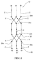




Classifications
-
- B—PERFORMING OPERATIONS; TRANSPORTING
- B21—MECHANICAL METAL-WORKING WITHOUT ESSENTIALLY REMOVING MATERIAL; PUNCHING METAL
- B21F—WORKING OR PROCESSING OF METAL WIRE
- B21F27/00—Making wire network, i.e. wire nets
- B21F27/12—Making special types or portions of network by methods or means specially adapted therefor
-
- B—PERFORMING OPERATIONS; TRANSPORTING
- B01—PHYSICAL OR CHEMICAL PROCESSES OR APPARATUS IN GENERAL
- B01J—CHEMICAL OR PHYSICAL PROCESSES, e.g. CATALYSIS OR COLLOID CHEMISTRY; THEIR RELEVANT APPARATUS
- B01J19/00—Chemical, physical or physico-chemical processes in general; Their relevant apparatus
- B01J19/32—Packing elements in the form of grids or built-up elements for forming a unit or module inside the apparatus for mass or heat transfer
-
- B—PERFORMING OPERATIONS; TRANSPORTING
- B01—PHYSICAL OR CHEMICAL PROCESSES OR APPARATUS IN GENERAL
- B01F—MIXING, e.g. DISSOLVING, EMULSIFYING OR DISPERSING
- B01F25/00—Flow mixers; Mixers for falling materials, e.g. solid particles
- B01F25/40—Static mixers
- B01F25/45—Mixers in which the materials to be mixed are pressed together through orifices or interstitial spaces, e.g. between beads
- B01F25/452—Mixers in which the materials to be mixed are pressed together through orifices or interstitial spaces, e.g. between beads characterised by elements provided with orifices or interstitial spaces
-
- B—PERFORMING OPERATIONS; TRANSPORTING
- B21—MECHANICAL METAL-WORKING WITHOUT ESSENTIALLY REMOVING MATERIAL; PUNCHING METAL
- B21F—WORKING OR PROCESSING OF METAL WIRE
- B21F27/00—Making wire network, i.e. wire nets
- B21F27/08—Making wire network, i.e. wire nets with additional connecting elements or material at crossings
- B21F27/10—Making wire network, i.e. wire nets with additional connecting elements or material at crossings with soldered or welded crossings
-
- B—PERFORMING OPERATIONS; TRANSPORTING
- B21—MECHANICAL METAL-WORKING WITHOUT ESSENTIALLY REMOVING MATERIAL; PUNCHING METAL
- B21F—WORKING OR PROCESSING OF METAL WIRE
- B21F27/00—Making wire network, i.e. wire nets
- B21F27/12—Making special types or portions of network by methods or means specially adapted therefor
- B21F27/18—Making special types or portions of network by methods or means specially adapted therefor of meshed work for filters or sieves
-
- B—PERFORMING OPERATIONS; TRANSPORTING
- B01—PHYSICAL OR CHEMICAL PROCESSES OR APPARATUS IN GENERAL
- B01J—CHEMICAL OR PHYSICAL PROCESSES, e.g. CATALYSIS OR COLLOID CHEMISTRY; THEIR RELEVANT APPARATUS
- B01J2219/00—Chemical, physical or physico-chemical processes in general; Their relevant apparatus
- B01J2219/32—Details relating to packing elements in the form of grids or built-up elements for forming a unit of module inside the apparatus for mass or heat transfer
- B01J2219/322—Basic shape of the elements
- B01J2219/32203—Sheets
- B01J2219/3221—Corrugated sheets
-
- B—PERFORMING OPERATIONS; TRANSPORTING
- B01—PHYSICAL OR CHEMICAL PROCESSES OR APPARATUS IN GENERAL
- B01J—CHEMICAL OR PHYSICAL PROCESSES, e.g. CATALYSIS OR COLLOID CHEMISTRY; THEIR RELEVANT APPARATUS
- B01J2219/00—Chemical, physical or physico-chemical processes in general; Their relevant apparatus
- B01J2219/32—Details relating to packing elements in the form of grids or built-up elements for forming a unit of module inside the apparatus for mass or heat transfer
- B01J2219/322—Basic shape of the elements
- B01J2219/32203—Sheets
- B01J2219/32213—Plurality of essentially parallel sheets
-
- B—PERFORMING OPERATIONS; TRANSPORTING
- B01—PHYSICAL OR CHEMICAL PROCESSES OR APPARATUS IN GENERAL
- B01J—CHEMICAL OR PHYSICAL PROCESSES, e.g. CATALYSIS OR COLLOID CHEMISTRY; THEIR RELEVANT APPARATUS
- B01J2219/00—Chemical, physical or physico-chemical processes in general; Their relevant apparatus
- B01J2219/32—Details relating to packing elements in the form of grids or built-up elements for forming a unit of module inside the apparatus for mass or heat transfer
- B01J2219/322—Basic shape of the elements
- B01J2219/32286—Grids or lattices
-
- B—PERFORMING OPERATIONS; TRANSPORTING
- B01—PHYSICAL OR CHEMICAL PROCESSES OR APPARATUS IN GENERAL
- B01J—CHEMICAL OR PHYSICAL PROCESSES, e.g. CATALYSIS OR COLLOID CHEMISTRY; THEIR RELEVANT APPARATUS
- B01J2219/00—Chemical, physical or physico-chemical processes in general; Their relevant apparatus
- B01J2219/32—Details relating to packing elements in the form of grids or built-up elements for forming a unit of module inside the apparatus for mass or heat transfer
- B01J2219/324—Composition or microstructure of the elements
- B01J2219/32408—Metal
-
- B—PERFORMING OPERATIONS; TRANSPORTING
- B01—PHYSICAL OR CHEMICAL PROCESSES OR APPARATUS IN GENERAL
- B01J—CHEMICAL OR PHYSICAL PROCESSES, e.g. CATALYSIS OR COLLOID CHEMISTRY; THEIR RELEVANT APPARATUS
- B01J2219/00—Chemical, physical or physico-chemical processes in general; Their relevant apparatus
- B01J2219/32—Details relating to packing elements in the form of grids or built-up elements for forming a unit of module inside the apparatus for mass or heat transfer
- B01J2219/324—Composition or microstructure of the elements
- B01J2219/32483—Plastics
-
- B—PERFORMING OPERATIONS; TRANSPORTING
- B01—PHYSICAL OR CHEMICAL PROCESSES OR APPARATUS IN GENERAL
- B01J—CHEMICAL OR PHYSICAL PROCESSES, e.g. CATALYSIS OR COLLOID CHEMISTRY; THEIR RELEVANT APPARATUS
- B01J2219/00—Chemical, physical or physico-chemical processes in general; Their relevant apparatus
- B01J2219/32—Details relating to packing elements in the form of grids or built-up elements for forming a unit of module inside the apparatus for mass or heat transfer
- B01J2219/328—Manufacturing aspects
-
- B—PERFORMING OPERATIONS; TRANSPORTING
- B01—PHYSICAL OR CHEMICAL PROCESSES OR APPARATUS IN GENERAL
- B01J—CHEMICAL OR PHYSICAL PROCESSES, e.g. CATALYSIS OR COLLOID CHEMISTRY; THEIR RELEVANT APPARATUS
- B01J2219/00—Chemical, physical or physico-chemical processes in general; Their relevant apparatus
- B01J2219/32—Details relating to packing elements in the form of grids or built-up elements for forming a unit of module inside the apparatus for mass or heat transfer
- B01J2219/33—Details relating to the packing elements in general
- B01J2219/3306—Dimensions or size aspects
Definitions
- This invention relates to a column packing filled in a device which is divided in a plurality of chambers or channels connected to one another and performs material transfer, heat exchange or mixing between gases, liquids or gas and liquid.
- the invention relates also to a method for manufacturing such column packing.
- Japanese Patent Application Laid-open Publication No. Hei 3-203976 discloses a column packing of this type.
- This column packing is made up of a plurality of permeable sheets which are disposed in parallel to one another and extend in the direction of a main stream of fluid. Projecting portions of these permeable sheets are disposed in the direction that crosses the main stream of fluid and these projections function as spacers between the adjacent permeable sheets.
- This packing (hereinafter referred to as "X-packing" because the cross section of a joint portion between two adjacnetn permeable sheets assumes the shape of the letter X) is beneficial in that fluid flowing down along the permeable sheets is repeatedly joined, mixed, horizontally dispersed and redistributed at each joint of the permeable sheets.
- fluid flow which was not uniform when it was charged in the device gradually becomes uniform resulting in an optimum material transfer or heat exchange.
- gas charged in the device passes through the liquid flowing along the inclined surfaces of the permeable sheets and necessary contact between the gas and the liquid is achieved by contacting the gas with the liquid while the gas passes through the permeable sheets, so that material transfer or heat exchange can be effected efficiently with a minimum pressure loss.
- this X-packing manufactured by the above described prior art method is used as a packing loaded in, e.g., a gas-liquid mixing device
- the packing 50 of Fig. 22 is erected in the device and liquid from a distributor is caused to flow from the top to the bottom, i.e., in the direction of arrow A.
- an object of the invention to provide an X-packing capable of accurately achieving uniform collection and redistribution of liquid at joints of the X-packing.
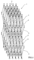
- a packing 1 as shown in the schematic perspective view of Fig. 1 can be obtained.
- This packing 1 has, as shown in the partial perspective view of Fig. 2, has a unit structure 2 which is a combination of two quadruple pyramids which as a common base and apexes which are directed in the opposite directions.
- the three-dimensional netlike structure is formed by disposing a plurality of the unit structures 2 in vertical and horizontal directions .
- four line elements 3 constitute four sides of the respective quadruple pyramids and respective apexes 2a of the two quadruple pyramids and joints 2b of the two quadruple pyramids are formed by conversion and dispersion of four line elements. Accordingly, no element corresponding to the horizontal threads in the prior art X-packing is used at all in this unit structure 2.
- the packing 1 manufactured by the method of the invention in a device such as a gas-liquid contact device, liquid from a distributor flows in the direction of arrow B in Fig. 1 and, since no element corresponding to the horizontal threads is used in the packing 1, the liquid which has fallen upon the top of the packing 1 does not produce a drift which is caused by flow of the liquid toward a laterally lower portion even if there is an error in installing the packing 1 in the device and, therefore, collection and downward redistribution of the liquid at the two vertical apexes 2a and joints 2b of the two quadruple pyramids of the unit structure 2 are performed uniformly.
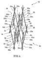
- a packing 30 as shown in the schematic perspective view of Fig. 3 can be obtained.
- This packing 30 has, as shown in the partial perspective view of Fig. 4, a unit structure 32 which is a combination of three triangular pyramids 33 each having an apex 33a and three sides 33b and three triangular pyramids 34 each having an apex 34a directed in the opposite direction to the apex 33a and three sides 34b.
- the three-dimensional net-like structure is formed by disposing a plurality of the unit structures 32 in vertical and horizontal directions.
- the respective sides 33b and 34b are formed with line elements. More specifically, three line elements constitute the three sides 33b and 34b of the triangular pyramids 33 and 34 and the apexes 33a and 34a of the respective triangular pyramids and joints 35 of the sides of the respective triangular pyramids are formed by conversion and dispersion of three line elements.
- no element corresponding to the horizontal threads is provided at all and, therefore, the same effect as the one described above with respect to the unit structure 2 can be achieved. That is, liquid flows in the direction of arrow C in Fig. 3 and collection and downward redistribution of the liquid at the apexes 33a and 34a and the joints 35 of the triangular pyramids 33 and 34 of the unit structure 32 are performed uniformly.
- the present invention can be applied not only to the column packing used in devices such as a gas-liquid mixing device but also to manufactring of other three-dimensional net-like structure such as ones used for a mist eliminator, a multi-layer filtering film and aggregate.
- a method for manufacturing a three-dimensional net-like structure including a mist eliminator and a multi-layer filtering film formed by conversion and dispersion of four line elements comprising steps of:
- a method for manufacturing a three-dimensional net-like structure including a mist eliminator and a multi-layer filtering film formed by conversion and dispersion of three line elements comprising:
- a packing made of a three-dimensional net-like structure which constitutes an internal structure of a device which performs material transfer, heat exchange or mixing between gases, liquids or gas and liquid, said internal structure being divided in a plurality of chambers or channels connected to one another and said three-dimensional net-like structure being formed by conversion and dispersion of four line elements wherein a converging portion of the four line elements is formed by mutual contact of undulating nets having parallel undulating bulging portions at necessary portions.
- a packing made of a three-dimensional net-like structure which constitutes an internal structure of a device which performs material transfer, heat exchange or mixing between gases, liquids or gas and liquid, said internal structure being divided in a plurality of chambers or channels connected to one another and said three-dimensional net-like structure being formed by conversion and dispersion of three line elements wherein a converging portion of the three line elements is formed by mutual contact of undulating nets having parallel undulating bulging portions at necessary portions.
- a three-dimensional net-like structure including a mist eliminator and a multi-layer filtering film formed by conversion and dispersion of four line elements wherein a converging portion of the four line elements is formed by mutual contact of undulating nets having parallel undulating bulging portions at necessary portions.
- a three-dimensional net-like structure including a mist eliminator and a multi-layer filtering film formed by conversion and dispersion of three line elements wherein a converging portion of the three line elements is formed by mutual contact of undulating nets having parallel undulating bulging portions at necessary portions.
- This embodiment relates to a method for manufacturing the thee-dimensional net-like structure shown in Figs. 1 and 2.
- a line element used in the manufacturing method of the invention may be made of metal or plastic. There is no particular limitation in the material used for the line element and wire, twine or monofilament may be used as the line element. Since the line element is formed to an undulating net by pressing, the material for the line element must be capable of plastic deformation and have sufficient rigidity to maintain the undulating shape after pressing.
- the line element may be made of a monofilament or a single piece of wire but a line element made of wire or twine which is made by twisting thin steel lines or plastic lines is preferable because liquid flows along the space between the lines which constitute the wire or twine due to the capillary action and thereby enhance transfer of the liquid.
- seven steel lines each having a diameter of 0.1mm are twisted together to form a single steel wire and two of this steel wire are further twisted to a single wire and this wire is used as the line element 3.
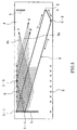
- This line element 3 is disposed on a line element placing table 4 shown in the plan view of Fig. 5.
- line element engaging pins 5 are provided at a predetermined interval in the four edge portions of the line element placing table 4.
- the line element 3 wound about a drum (not shown) is unwound from the drum and, as shown in Fig. 5 by way of example, is guided by a pin 5-1 provided in the left upper corner as viewed in Fig. 5 and thereafter is disposed over the entire surface of the line elements placing table 4, guided by pins 5-2, 5-3, 5-4, 5-5 and so on and extending in the order of arrows D, E, F, G etc.
- first line elements 2a which extend in parallel at a predetermined interval in a first direction X on a plane and second line elements 3b which extend in parallel at a predetermined interval in a second direction Y which is different from the first direction X are disposed in such a manner that the first line elements 3a cross the second line elements 3b at a desired angle ⁇ and the first and second line elements 3a and 3b are laid one upon the other as shown in Fig. 6.
- the first line elements 3a and the second line elements 3b thus disposed are spot-welded to each other at respective crossing points 6 by a known spot wedling machine as shown in Fig. 7 and a net 7 is thereby formed.
- This net 7 is removed from the line element placing table 4 and cut into a predetermined size.
- the net 7 is pressed by a mold 8 shown in Figs. 8 to 10 to form an undulating net.
- Fig. 8 is a front view of the mold 8 with a part thereof being omitted
- Fig. 9 is a partial plan view of the mold 8
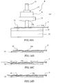
- Fig. 10A is a side view of the mold 8.
- an upper mold table 9 has slide portions 12, 12 which are slidably engaged on a pair of slide shafts 11, 11 erected upwardly from a lower mold table 10 and thereby can slide vertically along the slide shafts 11, 11.
- the upper mold table 9 has an upper mold 13 fixed thereon and the lower mold table 10 has a lower mold 14 fixed thereon.
- the lower mold 14 has a row of positioning pins 15 which are erected ahead of the upper mold 13 in the feeding direction of the net 7.
- the upper mold 13 and the lower mold 14 are formed on the lower surface of the upper mold 13 and the upper surface of the lower mold 14 with waveforms 13a and 14a which are to be imparted to the undulating net. These waveforms are such that crossing points 6 which are formed continuously in the first direction X and the second direction Y of the net 7 bulge alternately to form parallel undulating bulging portions.
- the net 7 is first positioned on the lower mold 14 with the upper mold 13 being located above the lower mold 14. The positioning is effected by inserting the positioning pins 15 in rhombic spaces of the net 7 formed by adjacent crossings 6 in the forward end portion of the net 7 in the feeding direction of the net 7.
- the upper mold 13 is lowered toward the lower mold 14 to press the net 7 between the upper mold 13 and the lower mold 14 and thereby impart the waveform as shown in Fig. 10B.
- the upper mold 13 is lifted, the net 7 is dieengaged from the positioning pins 15 and fed in the direction of arrow J so as to place a flat portion of the net 7 which has not been imparted with the waveform on the portion of the lower mold 14 having the waveform 14a.
- the net 7 is positioned again by inserting the positioning pins 15 in the rear end portion of the portion of the net 7 in which the waveform has been imparted.
- Fig. 11A is a plan view of the laying talbe 16
- Fig. 11B is a side view thereof
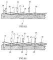
- Fig. 12 is a partial side section showing a manner of laying a second layer undulating net 17-2 on a first layer undulating net 17-1 and fixing them together
- Fig. 13 is a partial side section showing a manner of laying a third layer undulating net 17-3 on the second layer undulating net 17-2 and fixing them together
- Fig. 23 is a partial plan view showing the laying state of Fig. 13.
- the laying table 16 is formed on the upper surface thereof with a waveform 16a which is the same as the shape of the parallel undulating bulging portions of the net which are formed by alternate bulging of the crossing points 6 which are formed continuously in the first direction X and the second direction Y.
- a waveform 16a which is the same as the shape of the parallel undulating bulging portions of the net which are formed by alternate bulging of the crossing points 6 which are formed continuously in the first direction X and the second direction Y.
- positioning pins 18 for positioning the undulating net 17.
- Reference character 19 designates guide pins for holding electrode pins.
- FIGs. 12 and 13 only a part of an electrode 21 of a spot-welding machine is illustrated and illustration of the other portion of the spot-welding machine is omitted.
- the first layer undulating net 17-1 is positioned on the laying table 16 in such a manner that the positioning pins 18 are inserted in rhombic spaces formed between adjacent crossing points 6 of the undulating net 17-1 and, as shown in Fig. 12, the waveform of the first layer undulating net 17-1 conforms with the waveform of the laying table 16.
- electrode pins 20 are disposed in recessed portions of the first layer undulating net 17-1 and then the second layer undulating net 17-2 is laid on the first layer undulating net 17-1 in such a manner that the crossing points which are formed ocontinuously in the first direction X and the second direction Y of the first layer undulating net 17-1 alternately come into contact with and are separated from the crossing points which are formed continuously in the first direction X and the second direction Y of the second layer undulating net 17-2. Then, the crossing points which are in contact with each other of the first layer undulating net 17-1 and the second layer undulating net 17-2 are spot-welded by the spot welding machine 21.
- the third layer undulating net 17-3 is laid on the second layer undulating net 17-2 in such a manner that the crossing points which are formed ocontinuously in the first direction X and the second direction Y of the second layer undulating net 17-2 alternately come into contact with and are separated from the crossing points which are formed continuously in the first direction X and the second direction Y of the third layer undulating net 17-3. Then, the crossing points which are in contact with each other of the second layer undulating net 17-2 and the third layer undulating net 17-3 are spot-welded. Subsequently, fourth layer, fifth layer, .
- n-th layer (n being any integer) undulating nets are laid in said order in the same manner as described above and crossing points which are in contact with each other between immediately adjacent undulating nets are spot-welded.
- the packing 1 made of the three-dimensional net-like structure as shown in Fig. 1 is formed.
- first line elements 3a which extend in parallel at a predetermined interval in a first direction X on a plane
- second line elements 3b which extend in parallel at a predetermined interval in a second direction Y which is different from the first direction X are disposed in such a manner that the first line elements 3a cross the second line elements 3b at a desired angle ⁇ and the first and second line elements 3a and 3b are laid one upon the other as shown in Fig. 6.
- the first line elements 3a and the second line elements 3b thus disposed are spot-welded to each other at respective crossing points 6 by a known spot welding machine as shown in Fig. 7 and a net 7 is thereby formed.
- This net 7 is removed from the line element placing table 4 and cut into a predetermined size.
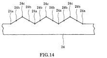
- This mold 8 is of a construction similar to the mold shown in Figs. 8 to 10 but the waveforms which are formed on the lower surface of the upper mold and the upper surface of the lower mold are different from those shown in Figs. 8 to 10. That is, as will be seen in an example of the waveform on the lower mold 24 shown in the side view of Fig. 14, the waveforms are such that crossing points formed continuously in the first direction X and the second direction Y sequentially constitute the lowest level 24a, lower side middle level 24b and upper side middle level 24c.
- the net 7 is disposed on the lower mold 24 shown in Fig. 14 and the upper mold (not shown) having a waveform which conforms with the the waveform of the lower mold 24 is lowered to press the net 7.
- the upper mold not shown
- a plurality of parallel undulating bulging portions are formed and thereby a first undulating net 25-1 is formed in such a manner that one of the crossing points continuously formed in the first direction and the second direction constitutes a crossing point 24a (shown by a black square) of the lowest level in forming of a unit three-dimensional net-like structure, a crossing point adjacent to the crossing point 24a of the lowest level constitutes a crossing point 24b (shown by a black circle) of a lower side middle level in forming of the unit three-dimensional net-like structure, a crossing point adjacent to the crossing point 24b of the lower side middle level constitutes a crossing point 24c (shown by a white circle) of an upper side middle level in forming of the unit three-dimensional net-like structure, a crossing point adjacent to the crossing point 24c of the upper side middle level constitutes a crossing point 24b of the lower side middle level in forming of the unit three-dimensional netlike structure, a crossing point adjacent to the crossing point 24b of the lower side middle middle
- Wire which is of the same structure as the line elements of the first undulating net 25-1 is used as the line element of the second undulating net and this line element is disposed over the line element placing table.
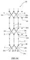
- This line element placing table is similar to the line element placing table 4 but is different from the line element placing table 4 in that, as shown in Fig. 16, pairs of guide pins 26 for guiding the line elements are provided at a predetermined interval on the table.
- the line elements are disposed in the following manner.
- first line elements 27 extend in parallel at a predetermined interval in the first direction X on the line element placing table, bend at a position 24b corresponding to the crossing point 24b of the lower side middle level of the first undulating net 25-1 at a predetermined angle, passing between a pair of guide pins 26 and being guided by them, and extend in a third direction Z.
- the first line elements 27 then bend at a position 24b corresponding to the next crossing point 24b of the lower side middle point of the first undulating net 25-1 at the predetermined angle, guided by the pair of guide pins 26, and extend in the second direction Y.
- the first line elements then bend at a position 24b corresponding to the crossing point 24b of the next lower side middle level of the first undulating net 25-1 at the predetermined angle, guided by the pair of guide pins 26, and extend in the third direction Z again.
- the first line elements then bend at a position 24b corresponding to the crossing point 24b of the next lower side middle level of the first undulating net 25-1 at the predetermined angle and repeat the cycle of extending in the first direction X, the third direction Z, the second direction Y and the third direction Z.
- Second line elements 28 extend in parallel at a predetermined interval in the second direction Y on the line element placing table, bend at a position 24b corresponding to the crossing point 24b of the lower side middle level of the first undulating net 25-1 at a predetermined angle, guided by the pair of guide pins 26, and extend in the third direction Z.
- the second line elements then bend at a position 24b corresponding to the crossing point 24b of the next lower side middle point of the first undulating net 25-1 at the predetermined angle, guided by the pair of guide pins 26, and extend in the first direction X.
- the second line elements then bend at a position 24b corresponding to the crossing point 24b of the next lower side middle level of the first undulating net 25-1 at the predetermined angle, guided by the pair of guide pins 26, and extend in the third direction Z again.
- the second line elements then bend at a position 24b corresponding to the crossing point 25b of the next lower side middle level of the first undulating net 25-1 at the predetermined angle, guided by the pair of guide pins 25, and repeat the cycle of extending in the second direction Y, the third direction Z, the first direction X and the third direction Z.
- the first line elements 27 and the second line elements 28 are disposed in such a manner that the first line elements 27 and the second line elements 28 cross each other at the desired angle in their portions extending in the first direction X or the second direction Y at positions 24c corresponding to the crossing points 24c of the upper side middle level of the first undulating net 25-1 and extend jointly one being laid upon the other in their portions extending in the third direction Z.
- the first line elements 27 are fixed to the second line elements 28 by spot welding at the respective crossing points thereof and also at joining points and separating points of their portions extending in the third direction Z and thereby a net 29 is formed.
- This net 29 is removed from the line element placing table and cut to a predetermined size.
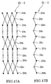
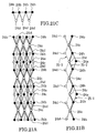
- Fig. 17A is a partial front view of this second undulating net 25-2 and Fig. 17B is a side view thereof.
- the white circle in Figs. 17A and 17B designates the upper side middle level 24c and the black circle the lower side middle level 24b.
- Fig. 16 one of the two joining line elements extending in the direction Z is illustrated on the upper side and the other on the lower side whereas in Fig. 17, the two line elements extending in the direction Z are shown in the state in which the two line elements are disposed in parallel to each other for convenience of illustration.
- Wire which is of the same structure as the line elements of the first and second undulating nets 25-1 and 25-2 is used as the line element of the third undulating net and this line element is disposed on the line element placing table used for forming of the net 29 of the second undulating net 25-2.
- first line elements 40 extend in parallel at a predetermined interval in the third direction Z on the line element placing table, bend at a position 24b corresponding to the crossing point 24b of the lower side middle level of the first undulating net 25-1 at a predetermined angle, guided by the pair of guide pins 26, and extend in the second direction Y.
- the first line element then bend at a position 24b corresponding to the crossing point 24b of the next lower side middle point of the first undulating net 25-1 at the predetermined angle, guided by the pair of guide pins 26, and extend in the third direction Z again.
- the first line elements bend at a position 24b corresponding to the crossing point 24b of the next lower side middle level of the first undulating net 25-1 at the predetermined angle, guided by the pair of guide pins 26, and extend in the first direction X.
- the first line element then bend at a position 24b corresponding to the crossing point 24b of the next lower side middle level of the first undulating net 25-1 at the predetermined angle and repeat the cycle of extending in the third direction Z, the second direction Y, the third direction Z and the first direction X.
- Second line elements 41 extend in parallel at a predetermined interval in the third direction Z on the line element placing table, bend at a position 24b corresponding to the crossing point 24b of the lower side middle level of the first undulating net 25-1 at a predetermined angle and extend in the first direction X.
- the second line elements then bend at a position 24b corresponding to the crossing point 24b of the next lower side middle point of the first undulating net 25-1 at the predetermined angle and extend in the third direction again Z.
- the second line elements then bend at a position 24b corresponding to the crossing point 24b of the next lower side middle level of the first undulating net 25-1 at the predetermined angle and extend in the second direction Y.
- the second line elements then bend at a position 24b corresponding to the crossing point 24b of the next lower side middle level of the first undulating net 25-1 at the predetermined angle and repeat the cycle of extending in the third direction Z, first direction X, the third direction Z and the second direction Y.
- the first line elements 40 and the second line elements 41 are disposed in such a manner that the first line elements 40 and the second line elements 41 cross each other at the desired angle in their portions extending in the first direction X or second direction Y at positions corresponding to middle positions of the portions extending in the third direction Z of the second undulating net 25-2 and extend jointly one being laid upon the other in their portions extending in the third direction Z.
- the first line elements 40 are fixed to the second line elements 41 by spot welding at the crossing points thereof and also at joining points and separating points of their portions extending in the third direction Z and a net 42 thereby is formed.
- the net 42 is removed from the line element placing table and cut to a predetermined size.
- Fig. 19A is a partial front view of the third undulating net 25-3 and Fig. 19B is a side view thereof.
- the white circle designates the upper side middle point 24c and the white square the highest level 24d of the unit three-dimensional net-like structure in the forming process.
- Fig. 18 one of the two joining line elements extending in the direction Z is illustrated on the upper side and the other on the lower side whereas in Fig.19, the two line elements extending in the direction Z are shown in the state in which the two line elements are disposed in parallel to each other for convenience of illustration.
- the first undulating net 25-1 is placed in such a manner that its crossing point 24a of the lowest level, crossing points 24b of the lower side middle level and crossing points 24c of the upper side middle level conform with the lowest level, lower side middle level and upper side middle level of the corresponding waveform in the laying table.
- the manner of laying the second undulating net 25-2 on the first undulating net 25-1 is shown in the partial front view of Fig. 20A and the side view of Fig. 20B.
- the undulating net 25-1 is shown by a solid line and the undulating net 25-2 is shown in a broken line.
- the second undulating net 25-2 is laid upon the first undulating net 25-1 in such a manner that the crossing points of the second undulating net 25-1 come into contact with the crossing points 24c of the upper side middle level of the first undulating net, 25-1, the joining points and the separating points of the portions extending in the third direction Z of the second undulating net 25-2 come into contact with the crossing points 24b of the lower side middle level of the first undulating net 25-1, and the undulating bulging portions at the middle positions of the portions extending in the third direction Z of the second undulating net 25-2 are separated from the crossing points 24a of the lowest level of the first undulating net 25-1 and form the upper side middle level 24c of the unit three-dimensional net-like structure;
- Fig. 21 shows a manner of laying the third undulating net 25-3 upon the second undulating net 25-2.
- Fig. 21A is a front view thereof
- Fig. 21B is a side view thereof
- Fig. 21C is a top plan view thereof.
- the first undulating net 25-1 and the second undulating net 25-2 are shown by solid lines and the third undulating net 25-3 is shown by a broken line.
- the third undulating net 25-3 is laid upon the second undulating net 25-2 in such a manner that the crossing points of the third undulating net 25-3 come into contact with the undulating bulging portions at the middle positions of the portions extending in the third direction Z of the second undulating net 25-2, the portions extending in the third direction Z of the third undulating net 25-3 come into contact, at their middle positions, with the crossing points of the second undulating net 25-2, and the undulating bulging portions at the joining points and the separating points of the portions extending in the third direction Z of the third undulating net 25-3 are separated from the second undulating net 25-2 and form the highest level 24d of the unit three-dimensional net-like structure.
- the first undulating net 25-1, the second undulating net 25-2 and the third undulating net 25-3 are fixed together at necessary points among points of contact thereof.
- the crossing points 24b of the first undulating net 25-1 and the joining and separating points 24b of the portion extending in the third direction Z of the second undulating net 25-2 are fixed together by spot welding
- the crossing points 24c of the second undulating net 25-2 and the middle point 24c of the portion extending in the third direction Z of the third undulating net 25-3 are fixed together by spot welding
- the middle point 24c of the portion extending in the third direction Z of the second undulating net 25-2 and the crossing point 24c of the third undulating net 25-3 are fixed together by spot welding.
- the structure consisting of the first to third undulating nets are laid in plural layers and welded together to form the three-dimensional net-like structure 30 shown in Fig. 3.
- a three-dimensional net-like structure having a unit structure consisting of a polygonal pyramids each having an apex consisting of six line elements can be formed.
- fixing of the respective line elements and the undulating nets together is performed by spot welding.
- the invention is not limited to the spot welding but the line elements and undulating nets may be fixed together by other methods such as soldering or, in case the line elements are made of plastic, by heat melting.
Landscapes
- Chemical & Material Sciences (AREA)
- Mechanical Engineering (AREA)
- Engineering & Computer Science (AREA)
- Chemical Kinetics & Catalysis (AREA)
- Physics & Mathematics (AREA)
- Thermal Sciences (AREA)
- Organic Chemistry (AREA)
- Dispersion Chemistry (AREA)
- Physical Or Chemical Processes And Apparatus (AREA)
- Wire Processing (AREA)
- Filtering Materials (AREA)
- Separation By Low-Temperature Treatments (AREA)
- Buffer Packaging (AREA)
- Revetment (AREA)
- Gasket Seals (AREA)
- Extraction Or Liquid Replacement (AREA)
Abstract
Description
first line elements extending in parallel at a predetermined interval in the first direction on a plane, bending at a position corresponding to one of the crossing points of the lower side middle level of the first undulating net at a predetermined angle and extending in a third direction, bending at a position corresponding to the next lower side middle point of the first undulating net at the predetermined angle and extending in the second direction, bending at a position corresponding to the next lower side middle level of the first undulating net at the predetermined angle and extending in the third direction again, and bending at a position corresponding to the next lower side middle level of the first undulating net at the predetermined angle and repeating the cycle of extending in the first direction, the third direction, the second direction and the third direction, and
second line elements extending in parallel at a predetermined interval in the second direction on the plane, bending at a position corresponding to one of the crossing points of the lower side middle level of the first undulating net at a predetermined angle and extending in the third direction, bending at a position corresponding to the next lower side middle point of the first undulating net at the predetermined angle and extending in the first direction, bending at a position corresponding to the next lower side middle level of the first undulating net at the predetermined angle and extending in the third direction again, and bending at a position corresponding to the next lower side middle level of the first undulating net at the predetermined angle and repeating the cycle of extending in the second direction, the third direction, the first direction and the third direction
in such a manner that the first line elements and the second line elements cross each other at the desired angle in their portions extending in the first or second direction at positions corresponding to the crossing points of the upper side middle level of the first undulating net and extend jointly one being laid upon the other in their portions extending in the third direction;
first line elements extending in parallel at a predetermined interval in the third direction on a plane, bending at a position corresponding to one of the crossing points of the lower side middle level of the first undulating net at a predetermined angle and extending in the second direction, bending at a position corresponding to the next lower side middle point of the first undulating net at the predetermined angle and extending in the third direction again, bending at a position corresponding to the next lower side middle level of the first undulating net at the predetermined angle and extending in the first direction, and bending at a position corresponding to the next lower side middle level of the first undulating net at the predetermined angle and repeating the cycle of extending in the third direction, the second direction, the third direction and the first direction, and
second line elements extending in parallel at a predetermined interval in the third direction on the plane, bending at a position corresponding to one of the crossing points of the lower side middle level of the first undulating net at a predetermined angle and extending in the first direction, bending at a position corresponding to the next lower side middle point of the first undulating net at the predetermined angle and extending in the third direction again, bending at a position corresponding to the next lower side middle level of the first undulating net at the predetermined angle and extending in the second direction, and bending at a position corresponding to the next lower side middle level of the first undulating net at the predetermined angle and repeating the cycle of extending in the third direction, first direction, the third direction and the second direction
in such a manner that the first line elements and the second line elements cross each other at the desired angle in their portions extending in the first or second direction at positions corresponding to middle positions of the portions extending in the third direction of the second undulating net and extend jointly one being laid upon the other in their portions extending in the third direction;
first line elements extending in parallel at a predetermined interval in the first direction on a plane, bending at a position corresponding to one of the crossing points of the lower side middle level of the first undulating net at a predetermined angle and extending in a third direction, bending at a position corresponding to the next lower side middle point of the first undulating net at the predetermined angle and extending in the second direction, bending at a position corresponding to the next lower side middle level of the first undulating net at the predetermined angle and extending in the third direction again, and bending at a position corresponding to the next lower side middle level of the first undulating net at the predetermined angle and repeating the cycle of extending in the first direction, the third direction, the second direction and the third direction, and
second line elements extending in parallel at a predetermined interval in the second direction on the plane, bending at a position corresponding to one of the crossing points of the lower side middle level of the first undulating net at a predetermined angle and extending in the third direction, bending at a position corresponding to the next lower side middle point of the first undulating net at the predetermined angle and extending in the first direction, bending at a position corresponding to the next lower side middle level of the first undulating net at the predetermined angle and extending in the third direction again, and bending at a position corresponding to the next lower side middle level of the first undulating net at the predetermined angle and repeating the cycle of extending in the second direction, the third direction, the first direction and the third direction
in such a manner that the first line elements and the second line elements cross each other at the desired angle in their portions extending in the first or second direction at positions corresponding to the crossing points of the upper side middle level of the first undulating net and extend jointly one being laid upon the other in their portions extending in the third direction;
first line elements extending in parallel at a predetermined interval in the third direction on a plane, bending at a position corresponding to one of the crossing points of the lower side middle level of the first undulating net at a predetermined angle and extending in the second direction, bending at a position corresponding to the next lower side middle point of the first undulating net at the predetermined angle and extending in the third direction again, bending at a position corresponding to the next lower side middle level of the first undulating net at the predetermined angle and extending in the first direction, and bending at a position corresponding to the next lower side middle level of the first undulating net at the predetermined angle and repeating the cycle of extending in the third direction, the second direction, the third direction and the first direction, and
second line elements extending in parallel at a predetermined interval in the third direction on the plane, bending at a position corresponding to one of the crossing points of the lower side middle level of the first undulating net at a predetermined angle and extending in the first direction, bending at a position corresponding to the next lower side middle point of the first undulating net at the predetermined angle and extending in the third direction again, bending at a position corresponding to the next lower side middle level of the first undulating net at the predetermined angle and extending in the second direction, and bending at a position corresponding to the next lower side middle level of the first undulating net at the predetermined angle and repeating the cycle of extending in the third direction, first direction, the third direction and the second direction
in such a manner that the first line elements and the second line elements cross each other at the desired angle in their portions extending in the first or second direction at positions corresponding to middle positions of the portions extending in the third direction of the second undulating net and extend jointly one being laid upon the other in their portions extending in the third direction;
Claims (8)
- A method for manufacturing a packing made of a three-dimensional net-like structure which constitutes an internal structure of a device which performs material transfer, heat exchange or mixing between gases, liquids or gas and liquid, said internal structure being divided in a plurality of chambers or channels connected to one another and said three-dimensional net-like structure being formed by conversion and dispersion of four line elements, said method comprising steps of:(A) disposing first line elements extending in parallel at a predetermined interval in a first direction on a plane and second line elements extending in parallel at a predetermined interval in a second direction which is different from the first direction on the same plane in such a manner that the first line elements cross the second line elements at a desired angle and the first and second line elements are laid one upon the other;(B) fixing the first line elements to the second line elements at crossing points thereof and thereby forming a net;(C) pressing the net to form a plurality of parallel undulating bulging portions which bulge at alternate ones of the crossing points continuously formed in the first direction and the second direction and thereby forming an undulating net;(D) laying a second layer of the undulating net upon a first layer of the undulating net in such a manner that the crossing points continuously formed in the first direction and the second direction of the first layer of the undulating net alternately come into contact with and separate from the crossing points continuously formed in the first direction and the second direction of the second layer of the undulating net and thereafter fixing together the crossing points of the first layer of the undulating net and the second layer of the undulating net which are in contact with each other; and(E) laying a third layer of the undulating net upon the second layer of the undulating net in such a manner that the crossing points continuously formed in the first direction and the second direction of the second layer of the undulating net alternately come into contact with and separate from the crossing points continuously formed in the first direction and the second direction of the third layer of the undulating net and thereafter fixing together the crossing points of the second layer of the undulating net and the third layer of the undulating net which are in contact with each other; and thereafter superposing a fourth, a fifth ..... and n-th (n being any integer) layer of the undulating nets in the same manner and fixing together the crossing points of the respective layers of the undulating nets and the immediately lower layers of the undulating nets which are in contact with each other.
- A method for manufacturing a packing made of a three-dimensional net-like structure which constitutes an internal structure of a device which performs material transfer, heat exchange or mixing between gases, liquids or gas and liquid, said internal structure being divided in a plurality of chambers or channels connected to one another and said three-dimensional net-like structure being formed by conversion and dispersion of three line elements, said method comprising:(A) a step of forming a first undulating net comprising the following steps (a), (b) and (c):(a) disposing first line elements extending in parallel at a predetermined interval in a first direction on a plane and second line elements extending in parallel at a predetermined interval in a second direction which is different from the first direction on the same plane in such a manner that the first line elements cross the second line elements at a desired angle and are superposed one upon the other;(b) fixing the first line elements to the second line elements at crossing points thereof and thereby forming a net; and(c) pressing the net to form a plurality of parallel undulating bulging portions and thereby forming a first undulating net in such a manner that one of the crossing points continuously formed in the first direction and the second direction constitutes a crossing point of the lowest level in forming of a unit three-dimensional net-like structure, a crossing point adjacent to the crossing point of the lowest level constitutes a crossing point of a lower side middle level in forming of the unit three-dimensional net-like structure, a crossing point adjacent to the crossing point of the lower side middle level constitutes a crossing point of an upper side middle level in forming of the unit three-dimensional net-like structure, a crossing point adjacent to the crossing point of the upper side middle level constitutes a crossing point of the lower side middle level in forming of the unit three-dimensional net-like structure, a crossing point adjacent to the crossing point of the lower side middle level constitutes a crossing point of the lowest level in forming of the unit three-dimensional net-like strucuture, and subsequent crossing points constitute crossing points of the respective levels in the above cycle in forming of the unit three-dimensional net-like structure;(B) a step of forming a second undulating net comprising the following steps (a), (b) and (c):(a) disposing
first line elements extending in parallel at a predetermined interval in the first direction on a plane, bending at a position corresponding to one of the crossing points of the lower side middle level of the first undulating net at a predetermined angle and extending in a third direction, bending at a position corresponding to the next lower side middle point of the first undulating net at the predetermined angle and extending in the second direction, bending at a position corresponding to the next lower side middle level of the first undulating net at the predetermined angle and extending in the third direction again, and bending at a position corresponding to the next lower side middle level of the first undulating net at the predetermined angle and repeating the cycle of extending in the first direction, the third direction, the second direction and the third direction, and
second line elements extending in parallel at a predetermined interval in the second direction on the plane, bending at a position corresponding to one of the crossing points of the lower side middle level of the first undulating net at a predetermined angle and extending in the third direction, bending at a position corresponding to the next lower side middle point of the first undulating net at the predetermined angle and extending in the first direction, bending at a position corresponding to the next lower side middle level of the first undulating net at the predetermined angle and extending in the third direction again, and bending at a position corresponding to the next lower side middle level of the first undulating net at the predetermined angle and repeating the cycle of extending in the second direction, the third direction, the first direction and the third direction
in such a manner that the first line elements and the second line elements cross each other at the desired angle in their portions extending in the first or second direction at positions corresponding to the crossing points of the upper side middle level of the first undulating net and extend jointly one being laid upon the other in their portions extending in the third direction;(b) fixing the first line elements to the second line elements at the respective crossing points thereof and also at joining points and separating points of their portions extending in the third direction and thereby forming a net; and(c) pressing the net to form a plurality of parallel undulating bulging portions which bulge at the respective crossing points and also at middle positions of the portions extending in the third direction and thereby constitute the upper side middle level in forming of the unit three-dimensional netlike structure, and thereby forming a second undulating net;(C) a step of forming a third undulating net comprising the following steps (a), (b) and (c):(a) disposing
first line elements extending in parallel at a predetermined interval in the third direction on a plane, bending at a position corresponding to one of the crossing points of the lower side middle level of the first undulating net at a predetermined angle and extending in the second direction, bending at a position corresponding to the next lower side middle point of the first undulating net at the predetermined angle and extending in the third direction again, bending at a position corresponding to the next lower side middle level of the first undulating net at the predetermined angle and extending in the first direction, and bending at a position corresponding to the next lower side middle level of the first undulating net at the predetermined angle and repeating the cycle of extending in the third direction, the second direction, the third direction and the first direction, and
second line elements extending in parallel at a predetermined interval in the third direction on the plane, bending at a position corresponding to one of the crossing points of the lower side middle level of the first undulating net at a predetermined angle and extending in the first direction, bending at a position corresponding to the next lower side middle point of the first undulating net at the predetermined angle and extending in the third direction again, bending at a position corresponding to the next lower side middle level of the first undulating net at the predetermined angle and extending in the second direction, and bending at a position corresponding to the next lower side middle level of the first undulating net at the predetermined angle and repeating the cycle of extending in the third direction, first direction, the third direction and the second direction
in such a manner that the first line elements and the second line elements cross each other at the desired angle in their portions extending in the first or second direction at positions corresponding to middle positions of the portions extending in the third direction of the second undulating net and extend jointly one being laid upon the other in their portions extending in the third direction;(b) fixing the first line elements to the second line elements at the crossing points thereof and also at joining points and separating points of their portions extending in the third direction and thereby forming a net; and(c) pressing the net to form a plurality of parallel undulating bulging portions which bulge at the respective joining and separating points of the portions extending in the third direction and thereby constitute the highest level in forming of the unit three-dimensional net-like structure, and thereby forming a third undulating net;(D) a step of laying the second undulating net upon the first undulating net in such a manner that the crossing points of the second undulating net come into contact with the crossing points of the upper middle level of the first undulating net, the joining points and the separating points of the portions extending in the third direction of the second undulating net come into contact with the crossing points of the lower middle level of the first undulating net, and the undulating bulging portions at the middle positions of the portions extending in the third direction of the second undulating net are separated from the crossing points of the lowest level of the first undulating net and form the upper middle level of the unit three-dimensional net-like structure;(E) a step of laying the third undulating net upon the second undulating net in such a manner that the crossing points of the third undulating net come into contact with the undulating bulging portions at the middle positions of the portions extending in the third direction of the second undulating net, the portions extending in the third direction of the third undulating net come into contact, at their middle positions, with the crossing points of the second undulating net, and the undulating bulging portions at the joining points and the separating points of the portions extending in the third direction of the third undulating net are separated from the second undulating net and form the highest level of the unit three-dimensional net-like structure; and(F) a step of fixing the first undulating net, the second undulating net and the third undulating net together at necessary points among points of contact thereof. - A method for manufacturing a three-dimensional net-like structure including a mist eliminator and a multi-layer filtering film formed by conversion and dispersion of four line elements, said method comprising steps of:(A) disposing first line elements extending in parallel at a predetermined interval in a first direction on a plane and second line elements extending in parallel at a predetermined interval in a second direction which is different from the first direction on the same plane in such a manner that the first line elements cross the second line elements at a desired angle and the first and second line elements are laid one upon the other;(B) fixing the first line elements to the second line elements at crossing points thereof and thereby forming a net;(C) pressing the net to form a plurality of parallel undulating bulging portions which bulge at alternate ones of the crossing points continuously formed in the first direction and the second direction and thereby forming an undulating net;(D) laying a second layer of the undulating net upon a first layer of the undulating net in such a manner that the crossing points continuously formed in the first direction and the second direction of the first layer of the undulating net alternately come into contact with and separate from the crossing points continuously formed in the first direction and the second direction of the second layer of the undulating net and thereafter fixing together the crossing points of the first layer of the undulating net and the second layer of the undulating net which are in contact with each other; and(E) laying a third layer of the undulating net upon the second layer of the undulating net in such a manner that the crossing points continuously formed in the first direction and the second direction of the second layer of the undulating net alternately come into contact with and separate from the crossing points continuously formed in the first direction and the second direction of the third layer of the undulating net and thereafter fixing together the crossing points of the second layer of the undulating net and the third layer of the undulating net which are in contact with each other; and thereafter superposing a fourth, a fifth ..... and n-th (n being any integer) layer of the undulating nets in the same manner and fixing together the crossing points of the respective layers of the undulating nets and the immediately lower layers of the undulating nets which are in contact with each other.
- A method for manufacturing a three-dimensional net-like structure including a mist eliminator and a multi-layer filtering film formed by conversion and dispersion of three line elements, said method comprising:(A) a step of forming a first undulating net comprising the following steps (a), (b) and (c):(a) disposing first line elements extending in parallel at a predetermined interval in a first direction on a plane and second line elements extending in parallel at a predetermined interval in a second direction which is different from the first direction on the same plane in such a manner that the first line elements cross the second line elements at a desired angle and are superposed one upon the other;(b) fixing the first line elements to the second line elements at crossing points thereof and thereby forming a net; and(c) pressing the net to form a plurality of parallel undulating bulging portions and thereby forming a first undulating net in such a manner that one of the crossing points continuously formed in the first direction and the second direction constitutes a crossing point of the lowest level in forming of a unit three-dimensional net-like structure, a crossing point adjacent to the crossing point of the lowest level constitutes a crossing point of a lower side middle level in forming of the unit thee-dimensional net-like structure, a crossing point adjacent to the crossing point of the lower side middle level constitutes a crossing point of an upper side middle level in forming of the unit thee-dimensional net-like structure, a crossing point adjacent to the crossing point of the upper side middle level constitutes a crossing point of the lower side middle level in forming of the unit thee-dimensional net-like structure, a crossing point adjacent to the crossing point of the lower side middle level constitutes a crossing point of the lowest level in forming of the unit three-dimensional net-like strucuture, and subsequent crossing points constitute crossing points of the respective levels in the above cycle in forming of the unit three-dimensional net-like structure;(B) a step of forming a second undulating net comprising the following steps (a), (b) and (c):(a) disposing
first line elements extending in parallel at a predetermined interval in the first direction on a plane, bending at a position corresponding to one of the crossing points of the lower side middle level of the first undulating net at a predetermined angle and extending in a third direction, bending at a position corresponding to the next lower side middle point of the first undulating net at the predetermined angle and extending in the second direction, bending at a position corresponding to the next lower side middle level of the first undulating net at the predetermined angle and extending in the third direction again, and bending at a position corresponding to the next lower side middle level of the first undulating net at the predetermined angle and repeating the cycle of extending in the first direction, the third direction, the second direction and the third direction, and
second line elements extending in parallel at a predetermined interval in the second direction on the plane, bending at a position corresponding to one of the crossing points of the lower side middle level of the first undulating net at a predetermined angle and extending in the third direction, bending at a position corresponding to the next lower side middle point of the first undulating net at the predetermined angle and extending in the first direction, bending at a position corresponding to the next lower side middle level of the first undulating net at the predetermined angle and extending in the third direction again, and bending at a position corresponding to the next lower side middle level of the first undulating net at the predetermined angle and repeating the cycle of extending in the second direction, the third direction, the first direction and the third direction
in such a manner that the first line elements and the second line elements cross each other at the desired angle in their portions extending in the first or second direction at positions corresponding to the crossing points of the upper side middle level of the first undulating net and extend jointly one being laid upon the other in their portions extending in the third direction;(b) fixing the first line elements to the second line elements at the respective crossing points thereof and also at joining points and separating points of their portions extending in the third direction and thereby forming a net; and(c) pressing the net to form a plurality of parallel undulating bulging portions which bulge at the respective crossing points and also at middle positions of the portions extending in the third direction and thereby constitute the upper side middle level in forming of the unit three-dimensional netlike structure, and thereby forming a second undulating net;(C) a step of forming a third undulating net comprising the following steps (a), (b) and (c):(a) disposing
first line elements extending in parallel at a predetermined interval in the third direction on a plane, bending at a position corresponding to one of the crossing points of the lower side middle level of the first undulating net at a predetermined angle and extending in the second direction, bending at a position corresponding to the next lower side middle point of the first undulating net at the predetermined angle and extending in the third direction again, bending at a position corresponding to the next lower side middle level of the first undulating net at the predetermined angle and extending in the first direction, and bending at a position corresponding to the next lower side middle level of the first undulating net at the predetermined angle and repeating the cycle of extending in the third direction, the second direction, the third direction and the first direction, and
second line elements extending in parallel at a predetermined interval in the third direction on the plane, bending at a position corresponding to one of the crossing points of the lower side middle level of the first undulating net at a predetermined angle and extending in the first direction, bending at a position corresponding to the next lower side middle point of the first undulating net at the predetermined angle and extending in the third direction again, bending at a position corresponding to the next lower side middle level of the first undulating net at the predetermined angle and extending in the second direction, and bending at a position corresponding to the next lower side middle level of the first undulating net at the predetermined angle and repeating the cycle of extending in the third direction, first direction, the third direction and the second direction
in such a manner that the first line elements and the second line elements cross each other at the desired angle in their portions extending in the first or second direction at positions corresponding to middle positions of the portions extending in the third direction of the second undulating net and extend jointly one being laid upon the other in their portions extending in the third direction;(b) fixing the first line elements to the second line elements at the crossing points thereof and also at joining points and separating points of their portions extending in the third direction and thereby forming a net; and(c) pressing the net to form a plurality of parallel undulating bulging portions which bulge at the respective joining and separating points of the portions extending in the third direction and thereby constitute the highest level in forming of the unit three-dimensional net-like structure, and thereby forming a third undulating net;(D) a step of laying the second undulating net upon the first undulating net in such a manner that the crossing points of the second undulating net come into contact with the crossing points of the upper middle level of the first undulating net, the joining points and the separating points of the portions extending in the third direction of the second undulating net come into contact with the crossing points of the lower middle level of the first undulating net, and the undulating bulging portions at the middle positions of the portions extending in the third direction of the second undulating net are separated from the crossing points of the lowest level of the first undulating net and form the upper middle level of the unit three-dimensional net-like structure;(E) a step of laying the third undulating net upon the second undulating net in such a manner that the crossing points of the third undulating net come into contact with the undulating bulging portions at the middle positions of the portions extending in the third direction of the second undulating net, the portions extending in the third direction of the third undulating net come into contact, at their middle positions, with the crossing points of the second undulating net, and the undulating bulging portions at the joining points and the separating points of the portions extending in the third direction of the third undulating net are separated from the second undulating net and form the highest level of the unit three-dimensional net-like structure; and(F) a step of fixing the first undulating net, the second undulating net and the third undulating net together at necessary points among points of contact thereof. - A packing made of a three-dimensional net-like structure which constitutes an internal structure of a device which performs material transfer, heat exchange or mixing between gases, liquids or gas and liquid, said internal structure being divided in a plurality of chambers or channels connected to one another and said three-dimensional net-like structure being formed by conversion and dispersion of four line elements wherein a converging portion of the four line elements is formed by mutual contact of undulating nets having parallel undulating bulging portions at necessary portions.
- A packing made of a three-dimensional net-like structure which constitutes an internal structure of a device which performs material transfer, heat exchange or mixing between gases, liquids or gas and liquid, said internal structure being divided in a plurality of chambers or channels connected to one another and said three-dimensional net-like structure being formed by conversion and dispersion of three line elements wherein a converging portion of the three line elements is formed by mutual contact of undulating nets having parallel undulating bulging portions at necessary portions.
- A three-dimensional net-like structure including a mist eliminator and a multi-layer filtering film formed by conversion and dispersion of four line elements wherein a converging portion of the four line elements is formed by mutual contact of undulating nets having parallel undulating bulging portions at necessary portions.
- A three-dimensional net-like structure including a mist eliminator and a multi-layer filtering film formed by conversion and dispersion of thee line elements wherein a converging portion of the thee line elements is formed by mutual contact of undulating nets having parallel undulating bulging portions at necessary portions.
Applications Claiming Priority (2)
| Application Number | Priority Date | Filing Date | Title |
|---|---|---|---|
| JP5236399 | 1999-03-01 | ||
| JP5236399 | 1999-03-01 |
Publications (2)
| Publication Number | Publication Date |
|---|---|
| EP1033168A2 true EP1033168A2 (en) | 2000-09-06 |
| EP1033168A3 EP1033168A3 (en) | 2003-09-17 |
Family
ID=12912733
Family Applications (1)
| Application Number | Title | Priority Date | Filing Date |
|---|---|---|---|
| EP00104040A Withdrawn EP1033168A3 (en) | 1999-03-01 | 2000-02-26 | Column packing and method for manufacturing the same |
Country Status (9)
| Country | Link |
|---|---|
| US (3) | US6538225B1 (en) |
| EP (1) | EP1033168A3 (en) |
| KR (1) | KR100329005B1 (en) |
| CN (2) | CN1121262C (en) |
| AU (1) | AU743223B2 (en) |
| BR (1) | BR0000981A (en) |
| CA (1) | CA2299777C (en) |
| RU (1) | RU2174438C1 (en) |
| SG (1) | SG82684A1 (en) |
Cited By (3)
| Publication number | Priority date | Publication date | Assignee | Title |
|---|---|---|---|---|
| EP1155739A3 (en) * | 2000-05-19 | 2003-05-14 | Tadayoshi Nagaoka | Column packing and method for manufacturing the same |
| RU2224590C1 (en) * | 2003-01-29 | 2004-02-27 | Зиберт Генрих Карлович | A multilayer nozzle |
| EP1834693A1 (en) * | 2006-03-15 | 2007-09-19 | T & R engineering GmbH | Structured packing of woven tissue |
Families Citing this family (14)
| Publication number | Priority date | Publication date | Assignee | Title |
|---|---|---|---|---|
| JP2001009269A (en) * | 1999-04-27 | 2001-01-16 | Tadayoshi Nagaoka | Three-dimensional meshlike structure such as packing material in device for performing mass transfer or the like and its manufacture |
| US20040231306A1 (en) * | 2001-06-18 | 2004-11-25 | Peter Neumann | Exhaust gas particulate filter made of sintered metal |
| US8313439B2 (en) * | 2009-03-20 | 2012-11-20 | Massachusetts Institute Of Technology | Calibration of pulse transit time measurements to arterial blood pressure using external arterial pressure applied along the pulse transit path |
| CN102389655A (en) * | 2011-11-15 | 2012-03-28 | 南通诚信氨基酸有限公司 | Activated carbon filtering device used in production of amino acids |
| CN103691387A (en) * | 2013-12-13 | 2014-04-02 | 中建安装工程有限公司 | Circularly-arranged catalytic distillation packing |
| US10744426B2 (en) * | 2015-12-31 | 2020-08-18 | Crystaphase Products, Inc. | Structured elements and methods of use |
| US10054140B2 (en) | 2016-02-12 | 2018-08-21 | Crystaphase Products, Inc. | Use of treating elements to facilitate flow in vessels |
| EP4076719A1 (en) | 2019-12-20 | 2022-10-26 | Crystaphase Products Inc. | Resaturation of gas into a liquid feedstream |
| JP2023541252A (en) | 2020-09-09 | 2023-09-29 | クリスタフェーズ・プロダクツ・インコーポレーテッド | Process vessel entry zone |
| CN112209138B (en) * | 2020-10-20 | 2025-05-30 | 礼德滤材科技(苏州)有限责任公司 | Spiral Network Fully Automatic Networking Platform |
| CN114541027B (en) * | 2022-01-21 | 2022-12-06 | 东华大学 | Infrared stealth fabric based on orderly woven total reflection structure knitted body and manufacturing method thereof |
| KR102721386B1 (en) * | 2022-12-27 | 2024-10-24 | (주)동호테크 | A prefabricated booth for blocking electromagnetic waves |
| TWI852403B (en) * | 2023-03-14 | 2024-08-11 | 李育松 | Heat dissipation net for a heat dissipation water tower |
| FR3151081B1 (en) * | 2023-07-11 | 2025-10-31 | Freyssinet Aero Group | WIRE FILLING FOR A GAS-LIQUID EXCHANGE DEVICE WITH RADIAL HEAT TRANSFER CAPACITY |
Family Cites Families (18)
| Publication number | Priority date | Publication date | Assignee | Title |
|---|---|---|---|---|
| US1842121A (en) * | 1929-01-17 | 1932-01-19 | Francis B Riley | Apparatus for the formation of diagonal strand metallic patterns |
| US1922271A (en) * | 1933-01-03 | 1933-08-15 | Welded Fabrics Corp | Apparatus for formation and welding of crossed wire products |
| GB607288A (en) * | 1944-04-03 | 1948-08-27 | Francis Leopold Melville | Improvements in gas or vapour and liquid contacting methods and apparatus |
| US4208284A (en) * | 1965-05-11 | 1980-06-17 | Hahn Hans H | Apparatus for distribution separation processes |
| US3396761A (en) * | 1966-03-18 | 1968-08-13 | Sheller Globe Corp | Method and apparatus for producing a reticulated wire structure |
| CH477902A (en) * | 1967-08-16 | 1969-09-15 | Sulzer Ag | Process for the production of packing elements intended for mass transfer columns |
| AT312643B (en) * | 1970-05-29 | 1974-01-10 | Faigle Heinz | Trench installation for cooling towers |
| AT345642B (en) * | 1976-03-23 | 1978-09-25 | Evg Entwicklung Verwert Ges | MULTI-POINT WELDING MACHINE FOR MANUFACTURING A MESH OF CUTTING WIRE SHEETS THAT CROSS EACH OTHER DIRECTION |
| CA1232431A (en) * | 1982-06-18 | 1988-02-09 | Rolf P.C. Manteufel | Process and apparatus for the exchange of material and/or heat between and/or for mixing of gaseous and/or liquid substances |
| DE3907573A1 (en) * | 1989-03-09 | 1990-09-20 | Sulzer Ag | MULTIPLE-PULL WHEEL PACK |
| CN2065507U (en) * | 1989-12-17 | 1990-11-14 | 叶善园 | Grid semisoft filler |
| US5673726A (en) * | 1991-01-10 | 1997-10-07 | Nagaoka International Corporation | Method for weaving a multi-ply fabric packing with hexagonal cells |
| JPH07121357B2 (en) * | 1991-08-20 | 1995-12-25 | 日本ポリエステル株式会社 | Gas-liquid contact unit and gas-liquid contact device |
| US5527590A (en) * | 1993-03-18 | 1996-06-18 | Priluck; Jonathan | Lattice block material |
| JP3426675B2 (en) * | 1993-12-24 | 2003-07-14 | 関西電力株式会社 | Rectifier |
| RU2056933C1 (en) * | 1994-02-10 | 1996-03-27 | Товарищество с ограниченной ответственностью - Научно-производственная компания "Кедр-89" | Fitting on for heat-mass-exchanging apparatuses |
| WO1997002890A1 (en) * | 1995-07-08 | 1997-01-30 | Basf Aktiengesellschaft | Cloth or cloth-like packing which is subject to low pressure losses and has an ordered structure for use in material-exchange columns and rectification method using such packing |
| JPH09103671A (en) * | 1995-10-09 | 1997-04-22 | Mitsubishi Corp | Material and / or packing for heat exchange tower |
-
2000
- 2000-02-24 US US09/512,410 patent/US6538225B1/en not_active Expired - Fee Related
- 2000-02-25 SG SG200001042A patent/SG82684A1/en unknown
- 2000-02-26 EP EP00104040A patent/EP1033168A3/en not_active Withdrawn
- 2000-02-28 AU AU19483/00A patent/AU743223B2/en not_active Ceased
- 2000-02-28 CA CA002299777A patent/CA2299777C/en not_active Expired - Fee Related
- 2000-02-29 RU RU2000105099/12A patent/RU2174438C1/en not_active IP Right Cessation
- 2000-02-29 KR KR1020000010206A patent/KR100329005B1/en not_active Expired - Fee Related
- 2000-02-29 BR BR0000981-4A patent/BR0000981A/en not_active IP Right Cessation
- 2000-03-01 CN CN00103709A patent/CN1121262C/en not_active Expired - Fee Related
- 2000-03-01 CN CNA021506442A patent/CN1491741A/en active Pending
-
2002
- 2002-02-15 US US10/076,806 patent/US20020073669A1/en not_active Abandoned
- 2002-02-15 US US10/077,295 patent/US20020059786A1/en not_active Abandoned
Cited By (4)
| Publication number | Priority date | Publication date | Assignee | Title |
|---|---|---|---|---|
| EP1155739A3 (en) * | 2000-05-19 | 2003-05-14 | Tadayoshi Nagaoka | Column packing and method for manufacturing the same |
| RU2224590C1 (en) * | 2003-01-29 | 2004-02-27 | Зиберт Генрих Карлович | A multilayer nozzle |
| EP1834693A1 (en) * | 2006-03-15 | 2007-09-19 | T & R engineering GmbH | Structured packing of woven tissue |
| US7931255B2 (en) | 2006-03-15 | 2011-04-26 | T & R Engineering Gmbh | Fabric packing |
Also Published As
| Publication number | Publication date |
|---|---|
| US6538225B1 (en) | 2003-03-25 |
| KR100329005B1 (en) | 2002-03-20 |
| AU1948300A (en) | 2000-10-05 |
| US20020059786A1 (en) | 2002-05-23 |
| CA2299777C (en) | 2003-06-24 |
| SG82684A1 (en) | 2001-08-21 |
| RU2174438C1 (en) | 2001-10-10 |
| CA2299777A1 (en) | 2000-09-01 |
| US20020073669A1 (en) | 2002-06-20 |
| AU743223B2 (en) | 2002-01-24 |
| CN1491741A (en) | 2004-04-28 |
| CN1121262C (en) | 2003-09-17 |
| EP1033168A3 (en) | 2003-09-17 |
| BR0000981A (en) | 2000-10-10 |
| KR20000062694A (en) | 2000-10-25 |
| CN1265938A (en) | 2000-09-13 |
Similar Documents
| Publication | Publication Date | Title |
|---|---|---|
| CA2299777C (en) | Column packing and method for manufacturing the same | |
| CA2279152C (en) | Multiple uneven plate, multiple uneven plate bending mold, multiple uneven plate manufacturing method and separator using multiple uneven plate | |
| US5063000A (en) | Packing elements | |
| AU2009200229B2 (en) | Arrangement for splicing panels together to form a cylindrical screen | |
| DE1946066A1 (en) | Device for bringing gases into contact with liquids | |
| CA2346625C (en) | Column packing and method for manufacturing the same | |
| WO2010027011A1 (en) | Gas-liquid contacting mechanism in apparatus for performing mass transfer or the like | |
| CN1192173A (en) | Grid block material | |
| US3164891A (en) | Method of forming pin fin assemblies | |
| MXPA00002144A (en) | Column packing and method for manufacturing the same | |
| JP3687922B2 (en) | Random filler | |
| JP2000312823A (en) | Solid network structure such as filling body or the like in apparatus for effecting mass transfer or the like and manufacture thereof | |
| US7931255B2 (en) | Fabric packing | |
| JPH09206954A (en) | Method for manufacturing corrugated reinforcing mat | |
| JPH0889794A (en) | Filling | |
| JPS63144878A (en) | Manufacture of stainless grating | |
| JP4129410B2 (en) | Manufacturing method of grating | |
| JPH09915A (en) | Material and / or packing for heat exchange tower | |
| JP2002239665A (en) | Mesh and welding equipment for mesh formation | |
| JPH11319413A (en) | Inclined sedimentation flow passage mechanism | |
| JPH0824632A (en) | Liquid and / or heat exchange tower liquid collector | |
| JPH04217793A (en) | Manufacture of heat exchanger fin |
Legal Events
| Date | Code | Title | Description |
|---|---|---|---|
| PUAI | Public reference made under article 153(3) epc to a published international application that has entered the european phase |
Free format text: ORIGINAL CODE: 0009012 |
|
| AK | Designated contracting states |
Kind code of ref document: A2 Designated state(s): AT BE CH CY DE DK ES FI FR GB GR IE IT LI LU MC NL PT SE |
|
| AX | Request for extension of the european patent |
Free format text: AL;LT;LV;MK;RO;SI |
|
| PUAL | Search report despatched |
Free format text: ORIGINAL CODE: 0009013 |
|
| AK | Designated contracting states |
Kind code of ref document: A3 Designated state(s): AT BE CH CY DE DK ES FI FR GB GR IE IT LI LU MC NL PT SE |
|
| AX | Request for extension of the european patent |
Extension state: AL LT LV MK RO SI |
|
| RIC1 | Information provided on ipc code assigned before grant |
Ipc: 7B 29C 70/24 B Ipc: 7B 21F 27/18 B Ipc: 7B 01J 19/32 A |
|
| AKX | Designation fees paid | ||
| REG | Reference to a national code |
Ref country code: DE Ref legal event code: 8566 |
|
| STAA | Information on the status of an ep patent application or granted ep patent |
Free format text: STATUS: THE APPLICATION IS DEEMED TO BE WITHDRAWN |
|
| 18D | Application deemed to be withdrawn |
Effective date: 20040317 |