EP1032621B1 - Process for recovering high quality oil from refinery waste emulsions - Google Patents
Process for recovering high quality oil from refinery waste emulsions Download PDFInfo
- Publication number
- EP1032621B1 EP1032621B1 EP98958050A EP98958050A EP1032621B1 EP 1032621 B1 EP1032621 B1 EP 1032621B1 EP 98958050 A EP98958050 A EP 98958050A EP 98958050 A EP98958050 A EP 98958050A EP 1032621 B1 EP1032621 B1 EP 1032621B1
- Authority
- EP
- European Patent Office
- Prior art keywords
- oil
- emulsion
- stream
- water
- solids
- Prior art date
- Legal status (The legal status is an assumption and is not a legal conclusion. Google has not performed a legal analysis and makes no representation as to the accuracy of the status listed.)
- Expired - Lifetime
Links
- 239000000839 emulsion Substances 0.000 title claims description 157
- 238000000034 method Methods 0.000 title claims description 54
- 230000008569 process Effects 0.000 title claims description 50
- 239000002699 waste material Substances 0.000 title claims description 46
- 239000003921 oil Substances 0.000 claims description 148
- 239000003085 diluting agent Substances 0.000 claims description 96
- XLYOFNOQVPJJNP-UHFFFAOYSA-N water Substances O XLYOFNOQVPJJNP-UHFFFAOYSA-N 0.000 claims description 92
- 239000007787 solid Substances 0.000 claims description 82
- 229930195733 hydrocarbon Natural products 0.000 claims description 51
- 150000002430 hydrocarbons Chemical class 0.000 claims description 48
- 239000012071 phase Substances 0.000 claims description 40
- 239000000203 mixture Substances 0.000 claims description 37
- 239000004215 Carbon black (E152) Substances 0.000 claims description 35
- 230000005484 gravity Effects 0.000 claims description 32
- 239000010779 crude oil Substances 0.000 claims description 29
- 239000007788 liquid Substances 0.000 claims description 28
- 238000000926 separation method Methods 0.000 claims description 18
- 239000002002 slurry Substances 0.000 claims description 16
- 238000011084 recovery Methods 0.000 claims description 15
- 239000003208 petroleum Substances 0.000 claims description 12
- 238000002156 mixing Methods 0.000 claims description 11
- 239000012267 brine Substances 0.000 claims description 9
- HPALAKNZSZLMCH-UHFFFAOYSA-M sodium;chloride;hydrate Chemical compound O.[Na+].[Cl-] HPALAKNZSZLMCH-UHFFFAOYSA-M 0.000 claims description 9
- 238000007670 refining Methods 0.000 claims description 6
- 239000008186 active pharmaceutical agent Substances 0.000 claims description 5
- 230000009467 reduction Effects 0.000 claims description 5
- 239000000295 fuel oil Substances 0.000 claims description 4
- 239000002569 water oil cream Substances 0.000 claims description 4
- 238000011033 desalting Methods 0.000 claims description 3
- 239000012808 vapor phase Substances 0.000 claims description 3
- 239000003995 emulsifying agent Substances 0.000 claims description 2
- 238000010438 heat treatment Methods 0.000 claims description 2
- 235000019198 oils Nutrition 0.000 claims 67
- 239000003209 petroleum derivative Substances 0.000 claims 4
- 235000019476 oil-water mixture Nutrition 0.000 claims 3
- 239000012223 aqueous fraction Substances 0.000 claims 1
- 239000012141 concentrate Substances 0.000 claims 1
- 239000008394 flocculating agent Substances 0.000 claims 1
- 229910001385 heavy metal Inorganic materials 0.000 claims 1
- 238000002347 injection Methods 0.000 claims 1
- 239000007924 injection Substances 0.000 claims 1
- 238000009834 vaporization Methods 0.000 claims 1
- 230000008016 vaporization Effects 0.000 claims 1
- 238000004065 wastewater treatment Methods 0.000 claims 1
- UHOVQNZJYSORNB-UHFFFAOYSA-N Benzene Chemical compound C1=CC=CC=C1 UHOVQNZJYSORNB-UHFFFAOYSA-N 0.000 description 27
- YXFVVABEGXRONW-UHFFFAOYSA-N Toluene Chemical compound CC1=CC=CC=C1 YXFVVABEGXRONW-UHFFFAOYSA-N 0.000 description 9
- 239000000126 substance Substances 0.000 description 8
- 239000000654 additive Substances 0.000 description 7
- 239000002904 solvent Substances 0.000 description 7
- -1 for example Chemical class 0.000 description 6
- 238000009835 boiling Methods 0.000 description 5
- 150000003839 salts Chemical class 0.000 description 5
- 239000003381 stabilizer Substances 0.000 description 5
- 230000008901 benefit Effects 0.000 description 4
- 125000003118 aryl group Chemical group 0.000 description 3
- 239000000356 contaminant Substances 0.000 description 3
- 238000004821 distillation Methods 0.000 description 3
- 230000006872 improvement Effects 0.000 description 3
- 239000000463 material Substances 0.000 description 3
- 238000010992 reflux Methods 0.000 description 3
- 239000010802 sludge Substances 0.000 description 3
- 239000002351 wastewater Substances 0.000 description 3
- TWRXJAOTZQYOKJ-UHFFFAOYSA-L Magnesium chloride Chemical compound [Mg+2].[Cl-].[Cl-] TWRXJAOTZQYOKJ-UHFFFAOYSA-L 0.000 description 2
- VYPSYNLAJGMNEJ-UHFFFAOYSA-N Silicium dioxide Chemical compound O=[Si]=O VYPSYNLAJGMNEJ-UHFFFAOYSA-N 0.000 description 2
- FAPWRFPIFSIZLT-UHFFFAOYSA-M Sodium chloride Chemical compound [Na+].[Cl-] FAPWRFPIFSIZLT-UHFFFAOYSA-M 0.000 description 2
- 230000000996 additive effect Effects 0.000 description 2
- 239000004927 clay Substances 0.000 description 2
- 238000005260 corrosion Methods 0.000 description 2
- 230000007797 corrosion Effects 0.000 description 2
- 239000003599 detergent Substances 0.000 description 2
- 230000000694 effects Effects 0.000 description 2
- 230000007613 environmental effect Effects 0.000 description 2
- 239000002245 particle Substances 0.000 description 2
- 238000005191 phase separation Methods 0.000 description 2
- 230000000750 progressive effect Effects 0.000 description 2
- 239000004094 surface-active agent Substances 0.000 description 2
- UXVMQQNJUSDDNG-UHFFFAOYSA-L Calcium chloride Chemical compound [Cl-].[Cl-].[Ca+2] UXVMQQNJUSDDNG-UHFFFAOYSA-L 0.000 description 1
- RWSOTUBLDIXVET-UHFFFAOYSA-N Dihydrogen sulfide Chemical compound S RWSOTUBLDIXVET-UHFFFAOYSA-N 0.000 description 1
- 235000019738 Limestone Nutrition 0.000 description 1
- QAOWNCQODCNURD-UHFFFAOYSA-L Sulfate Chemical compound [O-]S([O-])(=O)=O QAOWNCQODCNURD-UHFFFAOYSA-L 0.000 description 1
- 230000009471 action Effects 0.000 description 1
- 238000013019 agitation Methods 0.000 description 1
- 125000000129 anionic group Chemical group 0.000 description 1
- 239000008346 aqueous phase Substances 0.000 description 1
- 239000001110 calcium chloride Substances 0.000 description 1
- 229910001628 calcium chloride Inorganic materials 0.000 description 1
- 125000002091 cationic group Chemical group 0.000 description 1
- 239000004568 cement Substances 0.000 description 1
- 238000005119 centrifugation Methods 0.000 description 1
- 239000003795 chemical substances by application Substances 0.000 description 1
- 238000005345 coagulation Methods 0.000 description 1
- 230000015271 coagulation Effects 0.000 description 1
- 230000003750 conditioning effect Effects 0.000 description 1
- 238000011109 contamination Methods 0.000 description 1
- 238000005336 cracking Methods 0.000 description 1
- 230000002950 deficient Effects 0.000 description 1
- 230000002939 deleterious effect Effects 0.000 description 1
- 238000010586 diagram Methods 0.000 description 1
- 238000004945 emulsification Methods 0.000 description 1
- 230000002708 enhancing effect Effects 0.000 description 1
- 238000007667 floating Methods 0.000 description 1
- 239000013056 hazardous product Substances 0.000 description 1
- 229910000037 hydrogen sulfide Inorganic materials 0.000 description 1
- 239000003350 kerosene Substances 0.000 description 1
- 239000006028 limestone Substances 0.000 description 1
- 229910001629 magnesium chloride Inorganic materials 0.000 description 1
- 229910052943 magnesium sulfate Inorganic materials 0.000 description 1
- CSNNHWWHGAXBCP-UHFFFAOYSA-L magnesium sulphate Substances [Mg+2].[O-][S+2]([O-])([O-])[O-] CSNNHWWHGAXBCP-UHFFFAOYSA-L 0.000 description 1
- 235000019341 magnesium sulphate Nutrition 0.000 description 1
- 238000004519 manufacturing process Methods 0.000 description 1
- 239000007764 o/w emulsion Substances 0.000 description 1
- 229920000642 polymer Polymers 0.000 description 1
- 238000002360 preparation method Methods 0.000 description 1
- 238000004064 recycling Methods 0.000 description 1
- 239000012056 semi-solid material Substances 0.000 description 1
- 239000000377 silicon dioxide Substances 0.000 description 1
- 239000011780 sodium chloride Substances 0.000 description 1
- XZPVPNZTYPUODG-UHFFFAOYSA-M sodium;chloride;dihydrate Chemical compound O.O.[Na+].[Cl-] XZPVPNZTYPUODG-UHFFFAOYSA-M 0.000 description 1
- 239000011343 solid material Substances 0.000 description 1
- 239000007790 solid phase Substances 0.000 description 1
- 239000004449 solid propellant Substances 0.000 description 1
- 239000000725 suspension Substances 0.000 description 1
- 238000010998 test method Methods 0.000 description 1
- 239000010409 thin film Substances 0.000 description 1
- 239000007762 w/o emulsion Substances 0.000 description 1
- 238000005406 washing Methods 0.000 description 1
Images
Classifications
-
- C—CHEMISTRY; METALLURGY
- C10—PETROLEUM, GAS OR COKE INDUSTRIES; TECHNICAL GASES CONTAINING CARBON MONOXIDE; FUELS; LUBRICANTS; PEAT
- C10G—CRACKING HYDROCARBON OILS; PRODUCTION OF LIQUID HYDROCARBON MIXTURES, e.g. BY DESTRUCTIVE HYDROGENATION, OLIGOMERISATION, POLYMERISATION; RECOVERY OF HYDROCARBON OILS FROM OIL-SHALE, OIL-SAND, OR GASES; REFINING MIXTURES MAINLY CONSISTING OF HYDROCARBONS; REFORMING OF NAPHTHA; MINERAL WAXES
- C10G33/00—Dewatering or demulsification of hydrocarbon oils
- C10G33/04—Dewatering or demulsification of hydrocarbon oils with chemical means
Definitions
- This invention describes an improvement in refinery operations whereby processable crude oil is recovered from refinery waste emulsions such as API slop oils and desalter rag layers.
- an envelope of solid or semi-solid material in a thin-film layer around the surface of each individual water droplet.
- This material may be inorganic, for example as clay platelets, or silica or limestone particles, or it may be organic such as wax-like or bitumen-like particles.
- These inorganic and organic solids act as emulsion stabilizers.
- the oil has a specific gravity approaching that of water and has a high viscosity, the difficulty of separating these types of oil emulsions is further compounded. The high viscosity greatly hampers the effectiveness of separation equipment.
- U.S. Patent No. 4,938,876 describes a process whereby emulsions can generally be broken by causing a portion of the normally water dispersed phase to flash into vapor by suddenly reducing pressure on the emulsion (flashing) as described in the patent.
- flashing The flashing action is extremely powerful even when only a small fraction, 10 percent by volume or less, of the dispersed phase is vaporized.
- the envelope around each droplet is thus shattered so the dispersed phase can be coalesced and separated by gravity, or enhanced gravity forces, when there is a sufficient divergence of specific gravity and a low viscosity.
- Suitable anti-emulsion chemicals are often added to prevent re-emulsification.
- U.S. Patent No. 4,812,225 describes a process for recovering oil from waste material in the form of sludge.
- the sludge is formed when oil refining waste is collected into a pit or pond and the waste solids, including some water and oil emulsion, settle to the bottom.
- the sludge is carefully analyzed for example for emulsion type and solids content, and then mixed with water, hydrocarbon diluent or conditioning agents, depending on the results of the analysis, and submitted to centrifugation.
- the resulting solid (waste) and liquid centrifugate phases are then separated, and the liquid centrifugate further separated into its aqueous and oil components.
- a process for recovering high-density petroleum oil from a refinery waste emulsion comprising the steps of: adding to and mixing with the refinery waste emulsion a light hydrocarbon diluent to reduce the viscosity and reduce the specific gravity of the oil in the refinery waste emulsion and to form an emulsion-diluent mixture; flashing said emulsion-diluent mixture into a vapor phase and a liquid stream having a water phase and an oil phase; and separating the oil phase from the water phase to recover the petroleum oil.
- a process is provided as defined in appended claim 12 for the recovery of refinable crude oil from refinery waste emulsion streams.
- a process is provided as defined in appended claim 23 for recovering clean refinable crude oil from a refinery desalter effluent brine.
- the virgin crude oils are subjected to mixing with about 5-6 percent wash water in one or two stages, usually in horizontal contacting desalter vessels.
- the crude is generally heated under pressure to lower its viscosity and its specific gravity, thus making it easier to wash the salt out and to separate the oil from the wash water.
- the crude oil may be heated to 93°C (200°F) or above, at pressures of 689 kPa (100psig) or more.
- This layer is normally decanted from the vessel and stored for mixing with other emulsion streams and processing to recover the oil.
- the bottoms liquids and solids are removed to be subjected to enhanced-gravity separation of the oil/water/solid phases using a hydroclone (hydrocyclone) or similar device. Normally, however, the viscosity and specific gravity of heavy oil makes any separation difficult.
- the bottoms effluent from the first stage flash chamber contains the heavy oil residue, solids and other trapped oil values as well as water. It is viscous and has a high specific gravity approaching that of water, making physical separation equipment practically useless.
- a light hydrocarbon diluent stream in an amount sufficient to reduce the viscosity of the heavy oil to less than about 0.03 Pa.s (30 centipoise), preferably below about 0.01 Pa.s (10 centipoise), and most preferably to about 0.001 Pa.s (1 centipoise).
- the amount of diluent which is added may be from about 10 percent to about 50 percent by volume based upon the amount of oil in the bottoms effluent stream. If no initial flash step is used, the amount of diluent is based upon the percentage of oil in the emulsion treated.
- the diluent is selected to act as a solvent for the oil phase to be separated from the water and solids. As such, it will also act to reduce the specific gravity of the oil phase to less than about 0.92 and the viscosity to less than 0.01 Pa.s (10 centipoise), thereby making it possible to easily separate the components using gravity or enhanced gravity procedures.
- the objective is separation and oil recovery, not any particular specific gravity.
- the light hydrocarbon diluent would normally boil at a temperature of from about -7°C (20° F) to about 77°C (170° F).
- the low boiling diluent, or solvent could be selected from light hydrocarbons such as, for example, C 3 through C 6 alkyl hydrocarbons, naphtha, aromatic distillate, aromatics such as toluene or mixtures of any of the foregoing. It is the solvency, availability and recovery that is important, not so much the individual, specific hydrocarbon diluents chosen. The determination of suitable light hydrocarbon can be easily made by routine experimentation well-known to those skilled in the art.
- This emulsion stream recovered from the dewatering hydroclone is blended with the emulsion directly decanted from the first-stage flash step and with the concentrated solids slurry from the desanding step which still may include some emulsified oil.
- other refinery emulsions such as API slop oils
- the desalter emulsions can be mixed with the desalter emulsions for a common recovery of oil in the second emulsion breaking flash step.
- the other refinery emulsions (such as API slop oil) can be brought to an adequate temperature and pressure so that upon pressure reduction these may flash into the first stage flash vessel along with the desalter effluent.
- the vapor stream from the second stage flash will contain additional light end hydrocarbons plus a considerable portion of the diluent along with the flashed water.
- the condensate from this stream is suitable for recycle and remix with the remaining liquids in the second-stage flash chamber, thereby keeping all of the diluent as a part of the separate oil phase along with the separate water phase.
- liquids from this flash chamber are no longer emulsified and there is now a low viscosity oil and an adequate gravity differential between the oil and water, they can be separated by conventional enhanced-gravity means such as a bank of desander hydroclones followed by a bank of dewatering hydroclones or by the use of centrifuges or combination of the two.
- the solids slurry from desander hydroclones can be dewatered by known steps such as the use of a centrifuge.
- the remaining oil phase is now dry crude oil plus the added diluent.
- the oil is suitable for processing in normal refinery crude oil distillation units.
- the diluent can be recovered as part of a normal refinery distillation process and recycled as needed or, alternatively, recovered in a separate diluent stripping system.
- the separated water is solids-free, low in benzene and suitable for conventional treatment.
- the final solids cake can be made relatively dry or, left alternatively, relatively wet for various economic disposal methods. In both cases, the solids cake will have a low benzene content.
- This process is useful for recovery of useful crude oil from the various refinery waste streams having emulsified oil such as desalter effluent streams, API separator oils, waste oils and the like. Characteristically, these slop streams have high viscosity, high specific gravity oil and often high solids and water. This is a flexible process which may be used by those skilled in the art to recover processable oil from many different refinery wastes.
- the process of the invention may include steps for the complete processing to recover crude oil, but not necessarily all of the steps described below.
- Refinery streams vary widely in characteristics, composition and properties. Many variations in treatment will be evident from the following description of methods for recovering the oil. Those skilled in the art will see many useful variations of the practice of this invention.
- the refinery streams to be treated by the practice of this invention are brought to a sufficiently high pressure and temperature to feed the oil through a flash system as described in U.S. Patent No. 4,938,876.
- the pressure may be in the range of 345 to 1724 kPa (50 to 250 psig) or in some cases even higher, and a pre-flash elevated temperature of from about 121°C (250° F) to about 177°C (350° F) is provided. Again, it depends upon the waste emulsion stream being processed.
- An emulsion stream taken directly from the desalter may already be above 121°C (250° F) and at about 1034 kPa (150 psig).
- This stream can be flashed by sudden pressure reduction at this point to take a vapor stream overhead and an intermediate oil-water emulsion stream and a solids stream containing recoverable oil as a bottoms.
- the emulsion will preferably be decanted out of the flash vessel and held for later processing.
- the bottoms stream will be removed from the vessel and diluted with a light hydrocarbon to reduce the viscosity of the waste emulsion stream to less than 0.03 Pa.s (30 centipoise), preferably from about 0.001 to about 0.005 Pa.s (1 to about 5 centipoise).
- the hydrocarbon added would normally be selected from C 3 to C 6 alkyl hydrocarbons, toluene, kerosene, aromatic distillates, or other light refinery streams or mixtures thereof, preferably with a boiling point of from about -7°C (20° F) to about -77°C (170° F).
- the selected hydrocarbon diluent from about 10 to 50 percent by volume, based upon the oil content of the desalter bottoms effluent, would be added, preferably, from about 15 to about 35 percent by volume.
- the diluent serves to reduce the specific gravity of the oil phase again making it easier to separate from the water phase.
- hydroclone separation be used to separate the solids, emulsions and free water.
- the water eliminated from the system at this point is suitable for further processing at a refinery treater.
- the streams are brought up to pressure and temperature in preparation for a second stage flash.
- Suitable de-emulsifying chemicals are added as needed to the pressurized diluted oil/water/solids emulsion stream in amounts in the range of 100 to 2000 ppm by volume. Neutralizers may also be added when required.
- the emulsions encountered in this process are broken by the flash step, but due to agitation in the following steps there may be a tendency to reestablish emulsions.
- the emulsions encountered are of the oil-in-water type, it is desirable to add a surfactant favoring water-in-oil emulsion.
- a surfactant favoring oil-in-water emulsion should be used. Only small quantities of these counter-emulsifiers should be necessary. In fact, over-dosing can be counter productive.
- the emulsion with additives mixed in is heated to an appropriate temperature in the range of from about 121°C to about 177°C (250° to about 350° F) and passed through an expansion valve into a second stage flash tank.
- This diluted, hot, pressurized waste emulsion stream and its additives is passed through the flash controller such that the flashing of the stream vaporizes about 2 to 15 percent of the emulsion/water/solvent blend.
- This flashing step causes water-oil emulsions to be broken into their separate components as described in U.S. Patent No. 4,938,876, with light ends passing out overhead to a condenser and run-down tank.
- the condensed vapors will yield a water layer and a hydrocarbon layer above it. Both of these layers may normally be recycled to mix with the second stage flash chamber bottoms.
- the hydrocyclone system may be preferably arranged in two stages, solids being removed in the first stage and water in the second.
- the solids from the first stage will contain some oil and other contaminants which may be removed by washing the solids in a continuous centrifuge using a detergent-containing water wash. The clean solids may then be safely disposed, as an additive for cement manufacture, as a solid fuel, or for land fill.
- the water separated in the second stage hydrocyclone will contain any soluble salts obtained from the crude oil, and may be discarded as a brine to conventional brine treating facilities.
- the overhead from the final hydrocyclone separator will contain the product oil and the diluent. Following standard engineering principles, this can easily be separated to recover the diluent for further use and free the product oil for further refining into saleable products. An alternate step would be to leave diluents in the recovered oil for final recovery and recycle as part of the refinery crude oil processing when this is more advantageous.
- An economic enhancement is derived from the practice of this invention.
- the separation of the diluent from the oil can be handled in a stripping column where a heated feed is introduced with the diluent coming off the top of the column and the oil from the bottom using a reboiler to supply additional heat and a reflux condenser at the column. Such strippers are popular refinery apparatus well-known to the skilled engineer.
- the foregoing invention will be illustrated by the discussion of the following example with the accompanying drawing to better illustrate a preferred embodiment of this invention.
- This invention is an improvement over that described in U.S. Patent No. 4,938,876, and is particularly advantageous in connection with the treatment of the viscous slop emulsified waste streams created during refinery processing.
- the process of this invention lends itself well to modularization and thus can be practiced using only the embodiments which are applicable for particular waste streams involved and the result desired.
- the improvement involves adding a diluent/solvent to the waste oil emulsion to reduce its viscosity and specific gravity.
- the diluent assists in a cleaner separation of the oil phase from the aqueous and solids phases in the broken emulsion.
- the process also provides for the removal of excess water in a first stage flash step thereby greatly enhancing the economy of the emulsion breaking system.
- This stream is released through a flash controller valve 12 into a first-stage flash chamber 14 where the pressure is about 69 kPa (10 psi gauge).
- Low boiling hydrocarbons (including benzene), water vapors and some contaminant low boiling materials such as hydrogen sulfide are released in the vapor phase and pass through line 16 on to a condenser 18 serving to condense most of the water and hydrocarbons, which are collected in stabilizer 19.
- the condenser 18 is operated at a temperature in the range of from 4 to 32°C (40° to 90° F).
- Flash chamber 14 may be operated at either subatmospheric conditions or superatmospheric conditions depending upon the most convenient operating parameters extant at the refinery, taking into consideration the emulsion characteristics of the streams being treated.
- the liquids and solids in flash chamber 14 settle to give a bottom layer containing mostly water and suspended or entrained solids, and an upper layer containing oil emulsified with some water.
- This emulsion layer is usually intractable, and is removed through line 20 through cooler 42 into emulsion surge tank 22.
- the aqueous bottom lower layer is encouraged to drain out of chamber 14 with a small amount of wash water entering at line 24, through line 26, to pump 28 to a bank of desanding hydrocyclones 30 for a separation of solids from the oil stream.
- a stream of light hydrocarbon diluent Prior to entering the hydrocyclone 30, a stream of light hydrocarbon diluent is added, through line 32, to this bottoms stream and blended in in-line mixer 34.
- This diluent stream may be from about 10 percent to about 50 percent by volume based upon the oil content of the desalter D effluent stream, preferably from about 15 to about 35 volume percent of the stream and is intended to lower the viscosity and specific gravity of the oil phase so that the mixture can be easily separated in hydrocyclones 30 and later in the process.
- the diluent is added to achieve preferred viscosity of from about 0.001 to about 0.005 Pa.s (1 to about 5 centipoise) and a specific gravity of less than about 0.90.
- the light hydrocarbon diluent would normally boil at a temperature of from about -7°C (20° F) to about 77°C (170° F).
- the low boiling diluent, or solvent could be selected from light hydrocarbons such as, for example, C 3 through C 6 alkyl hydrocarbons, naphtha, aromatic distillate, aromatics such as toluene or mixtures of any of the foregoing. It is the solvency, availability and recovery that is important, not so much the individual, specific hydrocarbon diluents chosen.
- the determination of suitable light hydrocarbon can be easily made by routine experimentation well-known to those skilled in the art from diluent already available in the refinery.
- the diluent may be advantageously added at one or more points in the process, but the overall amounts and criteria for addition herein are maintained.
- Mixer 34 preferably an in-line "KENICS" mixer, is provided to ensure thorough blending of the diluent and the other liquids in the stream.
- the blend is now fed into the desanding bank of hydrocyclones 30, from which a slurry of solids in water of perhaps 5 to 15 weight percent solids is taken out in line 36.
- a small amount of wash water is provided through line 40 to hydrocyclone 30 to ensure removal of solids.
- the solids slurry passes through line 36 to join the emulsions in line 20 and passes through cooler 42 into surge tank 22.
- the water-solids slurry from line 36 is only a small portion of the mixture in surge tank 22, about one percent or less, but includes some recoverable oil content.
- the overhead, essentially solids-free stream of water and the emulsions leave hydrocyclone 30 through line 38 and pass into the second bank of hydrocyclones 44, which serve to dewater the oil emulsions and diluent stream blend which exits as an overhead stream through line 46 and is fed to surge tank 22 through lines 36 and 20.
- the bottoms effluent from hydrocyclone 44 in line 48 is water containing small amounts of dissolved hydrocarbon, which passes through cooler 50 and is released through line 52 to join other refinery process wastewater for final treatment.
- the oil-rich emulsion from surge tank 22, diluted with the hydrocarbon, is taken via line 54 into a progressive cavity pump 56 to provide a pressure of from about 689 to about 1379 kPa (100 to about 200 psi gauge).
- Emulsion-breaking additive chemicals as described in U. S. Patent No. 4,938,876, in small dosages are injected at 58, followed by an in-line mixer 60. This stream passes through trim heater 62 to raise the temperature to about 149°C (300° F).
- the mixture is then released through flash control valve 64 into the second-stage flash chamber vessel 66 which is operated at approximately 69 kPa (10 psi gauge).
- the flash chamber vessel 66 may be operated at either subatmospheric conditions or superatmospheric conditions depending upon the most convenient operating parameters extant at the particular refinery, taking into consideration the emulsion characteristics.
- oil-water emulsion is broken with flashed vapors containing some light hydrocarbon diluent and water exiting vessel 66 via line 68 to condenser 70 and receiver 72 from which the water and hydrocarbon condensate are returned to vessel 66 through line 74.
- Non-condensible gasses are vented from receiver 72 through pressure control valve 76.
- the oil-water-solids slurry from vessel 66 passes out through line 78 into progressive cavity pump 80, through line 82 into a bank of desanding hydrocyclones 84, from which a substantially oil-free slurry of solids in water is discharged at line 86.
- the slurry may be washed with a water stream, optionally containing a small amount of detergent, entering through line 87.
- This slurry may advantageously be cooled to below 82°C (180° F) in cooler 88 and fed to centrifuge 90.
- the centrifuge 90 is designed to discharge "clean" water (essentially free of benzene) through line 92 to join wastewater stream 52 for final treatment.
- a concentrated solids stream is discharged from the centrifuge 90 through line 94 for processing as an essentially non-hazardous material, for disposition to a coker, other recycling options, or other final environmentally benign disposal alternatives.
- the stripper 106 is designed to take overhead substantially all the diluent (for recycle) and leave as bottoms dry, clean, desalted crude oil for charging to the refinery units for further processing. If desired, some diluent could be left in this crude stream.
- the stripper 106 has a pump-around reboiler, line 108, pump 110, reboiler 112, which supplies heat to strip the diluent, and final oil product discharge line 114.
- the overhead vapors in stripper 106 are partially condensed by reflux cooler 116 to provide some reflux, with the main stream of recovered diluent vapors passing through line 118 into condenser 120 and accumulator 122, from which recovered diluent exits through line 124.
- Non-condensible vapors leave the accumulator 122 and are released by line 126 through a pressure control valve.
- the non-condensibles from line 126 join other non-condensibles released from stabilizer 19, exiting at line 128.
- the stabilizer vessel 19 acts also as a decanter, allowing condensed water to be drained off via line 130 recycle as desalter make-up water, for benzene stripping or further treating.
- Condensed hydrocarbon light ends are decanted through line 132 to be remixed into the crude oil product through line. 134 to line 114. Alternatively, these light hydrocarbons can be sent via line 136 to a separate collecting point depending upon the refining needs.
Landscapes
- Chemical & Material Sciences (AREA)
- Oil, Petroleum & Natural Gas (AREA)
- Engineering & Computer Science (AREA)
- Chemical Kinetics & Catalysis (AREA)
- General Chemical & Material Sciences (AREA)
- Organic Chemistry (AREA)
- Production Of Liquid Hydrocarbon Mixture For Refining Petroleum (AREA)
Description
- This invention describes an improvement in refinery operations whereby processable crude oil is recovered from refinery waste emulsions such as API slop oils and desalter rag layers.
- In processing crude oil in refinery operations, the presence of intractable emulsions of high specific gravity crude oils often present serious problems leading to oil losses, contamination problems, corrosion, fouling or plugging problems, and expensive environmental treatment / disposal costs. These emulsions can arise during early processing steps at the refinery, such as desalting, and can also result from the collection of stop oil emulsions from all parts of the refinery. Many produced crude oils contain soluble inorganic salts, such as sodium chloride, calcium chloride, magnesium chloride or sulfate. The presence of such salts in a crude oil is very deleterious to the processing of the oil in a refinery, causing severe corrosion, poor cracking yields, plugging and, ultimately, equipment failure. It is, therefore, customary to desalt incoming crude at a refinery by mixing the crude with wash water and allowing the water phase to dissolve the salt and be separated in a desalter vessel.
- The intractable emulsions of oil, water and solids make adequate separation and oil recovery difficult. Often, the only answer is that such emulsions arising from the desalter are periodically discarded as are other intractable emulsions and slop streams throughout the refinery. This results in expensive treating or handling procedures or pollution problems, as well as the fact that processable crude oil is also lost with these intractable emulsions and slop streams..
- In most cases, complete separation of water from the oil is inhibited by the presence of an envelope of solid or semi-solid material in a thin-film layer around the surface of each individual water droplet. This material may be inorganic, for example as clay platelets, or silica or limestone particles, or it may be organic such as wax-like or bitumen-like particles. These inorganic and organic solids act as emulsion stabilizers. Furthermore, if the oil has a specific gravity approaching that of water and has a high viscosity, the difficulty of separating these types of oil emulsions is further compounded. The high viscosity greatly hampers the effectiveness of separation equipment.
- U.S. Patent No. 4,938,876 describes a process whereby emulsions can generally be broken by causing a portion of the normally water dispersed phase to flash into vapor by suddenly reducing pressure on the emulsion (flashing) as described in the patent. The flashing action is extremely powerful even when only a small fraction, 10 percent by volume or less, of the dispersed phase is vaporized. The envelope around each droplet is thus shattered so the dispersed phase can be coalesced and separated by gravity, or enhanced gravity forces, when there is a sufficient divergence of specific gravity and a low viscosity. Suitable anti-emulsion chemicals are often added to prevent re-emulsification. The process of the above mentioned patent is successfully operated on a wide variety of intractable emulsion/suspensions, but has been found deficient when the components of the emulsion are not amenable to gravity separation as mentioned above. The patent does not tell one skilled in the art how to deal with the problem of emulsified high specific gravity oil, and only combats high viscosity by heating.
- U.S. Patent No. 4,812,225 describes a process for recovering oil from waste material in the form of sludge. The sludge is formed when oil refining waste is collected into a pit or pond and the waste solids, including some water and oil emulsion, settle to the bottom. The sludge is carefully analyzed for example for emulsion type and solids content, and then mixed with water, hydrocarbon diluent or conditioning agents, depending on the results of the analysis, and submitted to centrifugation. The resulting solid (waste) and liquid centrifugate phases are then separated, and the liquid centrifugate further separated into its aqueous and oil components.
- Accordingly, it is an object of this invention to provide a process whereby the components of slop oil emulsions can be readily separated from each other after the emulsion is broken.
- It is a further object of this invention to provide a process whereby crude oil may be recovered from intractable refinery emulsions for refining as a product. It is a further object of this invention to provide not only for the maximum recovery of oil from refinery waste emulsions, but to allow for environmentally-benign disposal of solids and aqueous components of such waste.
- The foregoing objects and other objects will become obvious to those of ordinary skill in the art after considering this description and the drawing of how this advantage is accomplished by the following-described invention.
- In accordance with one aspect of the present invention, a process is provided for recovering high-density petroleum oil from a refinery waste emulsion comprising the steps of: adding to and mixing with the refinery waste emulsion a light hydrocarbon diluent to reduce the viscosity and reduce the specific gravity of the oil in the refinery waste emulsion and to form an emulsion-diluent mixture; flashing said emulsion-diluent mixture into a vapor phase and a liquid stream having a water phase and an oil phase; and separating the oil phase from the water phase to recover the petroleum oil.
- Certain preferred embodiments of the aforesaid process where the refinery waste emulsion is an aqueous waste refinery emulsion stream or an intractable refinery emulsion are defined in appended claims 2 and 4, respectively.
- In accordance with another aspect of the present invention, a process is provided as defined in appended
claim 12 for the recovery of refinable crude oil from refinery waste emulsion streams. - In accordance with yet a further aspect of the present invention, a process is provided as defined in appended claim 23 for recovering clean refinable crude oil from a refinery desalter effluent brine.
- In the desalting of heavy (high specific gravity, high viscosity) crude oils, or lighter crude oils containing emulsion stabilizers in the form of clay, asphaltenes, paraffins and other solids, the virgin crude oils are subjected to mixing with about 5-6 percent wash water in one or two stages, usually in horizontal contacting desalter vessels. The crude is generally heated under pressure to lower its viscosity and its specific gravity, thus making it easier to wash the salt out and to separate the oil from the wash water. Commonly, the crude oil may be heated to 93°C (200°F) or above, at pressures of 689 kPa (100psig) or more. The crude leaving the desalter through an upper outlet has a low salt-in-crude and sediment-in-crude content, and the salt-laden wash water, or "brine", exits the vessel through a lower-level outlet. For maximum utilization of the desalter's capacity, the water brine withdrawn will include an appreciable amount of oil under-carry in the form of the so-called oil-rich "rag layer" emulsion. Also, the layer at the very bottom will also include an appreciable amount of solids or the so-called "mud wash" which is normally withdrawn intermittently.
- In the practice of this invention where the recovery of every processable drop of oil is sought, it is particularly advantageous to combine these three bottom fractions into a single, water-continuous desalter effluent stream containing the brine, the oil-emulsion under-carry including the oil-wetted solids that remain in the oil phase, and the intermittent mud wash solids. This entire desalter effluent stream often contains more than 10 ppm benzene in the water phase. This mixed stream is already at desalter operating conditions of about 608 to 1115 kPa (5 to 10 atm gauge) and about 121°C (250° F) and, therefore, upon pressure reduction it may flash into a first stage flash vessel for separating a vapor stream (which will contain most of the dissolved benzene from the aqueous phase), an emulsion stream and an oil- containing solids stream. Most of the dissolved benzene will flash off with the overhead vapors thus leaving less than 10 ppm benzene in the unflashed water phase. A portion of the unflashed liquids may remain as a light emulsion floating above the rest of the liquid in the first stage flash chamber. This layer is normally decanted from the vessel and stored for mixing with other emulsion streams and processing to recover the oil. The bottoms liquids and solids are removed to be subjected to enhanced-gravity separation of the oil/water/solid phases using a hydroclone (hydrocyclone) or similar device. Normally, however, the viscosity and specific gravity of heavy oil makes any separation difficult.
- In the practice of this invention, the bottoms effluent from the first stage flash chamber contains the heavy oil residue, solids and other trapped oil values as well as water. It is viscous and has a high specific gravity approaching that of water, making physical separation equipment practically useless. In order to recover the oil from this stream in a condition for further processing in a refinery, it is mixed with a light hydrocarbon diluent stream in an amount sufficient to reduce the viscosity of the heavy oil to less than about 0.03 Pa.s (30 centipoise), preferably below about 0.01 Pa.s (10 centipoise), and most preferably to about 0.001 Pa.s (1 centipoise). The amount of diluent which is added may be from about 10 percent to about 50 percent by volume based upon the amount of oil in the bottoms effluent stream. If no initial flash step is used, the amount of diluent is based upon the percentage of oil in the emulsion treated. The diluent is selected to act as a solvent for the oil phase to be separated from the water and solids. As such, it will also act to reduce the specific gravity of the oil phase to less than about 0.92 and the viscosity to less than 0.01 Pa.s (10 centipoise), thereby making it possible to easily separate the components using gravity or enhanced gravity procedures. The objective is separation and oil recovery, not any particular specific gravity. The light hydrocarbon diluent would normally boil at a temperature of from about -7°C (20° F) to about 77°C (170° F). The low boiling diluent, or solvent, could be selected from light hydrocarbons such as, for example, C3 through C6 alkyl hydrocarbons, naphtha, aromatic distillate, aromatics such as toluene or mixtures of any of the foregoing. It is the solvency, availability and recovery that is important, not so much the individual, specific hydrocarbon diluents chosen. The determination of suitable light hydrocarbon can be easily made by routine experimentation well-known to those skilled in the art.
- The light hydrocarbon diluent selected is added in the sufficient amount to create the properties in the bottoms stream as discussed above, mixed and then fed to a hydrocyclone system for separation of solids as bottoms from other emulsions and water taken out overhead. The first hydrocyclone bank separates a concentrated slurry of solids (a de-sanding step) and then passes the de-sanded liquid mixture through a second dewatering hydrocyclone bank to remove as much non-emulsified water as practical. The remaining oily stream will be an oil-continuous, concentrated emulsion containing the intractable emulsion referred to above. This emulsion stream recovered from the dewatering hydroclone is blended with the emulsion directly decanted from the first-stage flash step and with the concentrated solids slurry from the desanding step which still may include some emulsified oil. If desired, other refinery emulsions (such as API slop oils) can be mixed with the desalter emulsions for a common recovery of oil in the second emulsion breaking flash step. Alternatively, the other refinery emulsions (such as API slop oil) can be brought to an adequate temperature and pressure so that upon pressure reduction these may flash into the first stage flash vessel along with the desalter effluent. This flashing activity may be through the same or through a different nozzle on the flash vessel as that used by the desalter flash activity. This mixture, which includes the diluent/solvent, is then subjected to a second emulsion-breaking flash step conducted as described in U.S. Patent No. 4,938,876. The second-stage flash chamber will generally operate at a pressure of 34 to 69 kPa (5 to 10 psig). This flash step completes breaking the emulsion, thereby leaving the discrete phases of oil, water and solids in a condition for successful gravity separation and oil recovery. The advantage of two separate flash steps is the greatly reduced volume of free water required to be heated prior to flashing and the presence of the diluent in finally breaking all the emulsions.
- The vapor stream from the second stage flash will contain additional light end hydrocarbons plus a considerable portion of the diluent along with the flashed water. The condensate from this stream is suitable for recycle and remix with the remaining liquids in the second-stage flash chamber, thereby keeping all of the diluent as a part of the separate oil phase along with the separate water phase.
- Since the liquids from this flash chamber are no longer emulsified and there is now a low viscosity oil and an adequate gravity differential between the oil and water, they can be separated by conventional enhanced-gravity means such as a bank of desander hydroclones followed by a bank of dewatering hydroclones or by the use of centrifuges or combination of the two. The solids slurry from desander hydroclones can be dewatered by known steps such as the use of a centrifuge. The remaining oil phase is now dry crude oil plus the added diluent. The oil is suitable for processing in normal refinery crude oil distillation units. The diluent can be recovered as part of a normal refinery distillation process and recycled as needed or, alternatively, recovered in a separate diluent stripping system. The separated water is solids-free, low in benzene and suitable for conventional treatment. The final solids cake can be made relatively dry or, left alternatively, relatively wet for various economic disposal methods. In both cases, the solids cake will have a low benzene content.
-
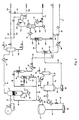
- Fig. 1 is a flow diagram of the preferred embodiment of the process of this invention for the recovery of processable crude oil from waste oil emulsions discharged in refinery operations.
- This process is useful for recovery of useful crude oil from the various refinery waste streams having emulsified oil such as desalter effluent streams, API separator oils, waste oils and the like. Characteristically, these slop streams have high viscosity, high specific gravity oil and often high solids and water. This is a flexible process which may be used by those skilled in the art to recover processable oil from many different refinery wastes.
- The process of the invention may include steps for the complete processing to recover crude oil, but not necessarily all of the steps described below. Refinery streams vary widely in characteristics, composition and properties. Many variations in treatment will be evident from the following description of methods for recovering the oil. Those skilled in the art will see many useful variations of the practice of this invention.
- The refinery streams to be treated by the practice of this invention are brought to a sufficiently high pressure and temperature to feed the oil through a flash system as described in U.S. Patent No. 4,938,876. The pressure may be in the range of 345 to 1724 kPa (50 to 250 psig) or in some cases even higher, and a pre-flash elevated temperature of from about 121°C (250° F) to about 177°C (350° F) is provided. Again, it depends upon the waste emulsion stream being processed. An emulsion stream taken directly from the desalter may already be above 121°C (250° F) and at about 1034 kPa (150 psig).
- This stream, particularly if a desalter effluent stream having high temperature and pressure exiting the desalter is used, can be flashed by sudden pressure reduction at this point to take a vapor stream overhead and an intermediate oil-water emulsion stream and a solids stream containing recoverable oil as a bottoms. The emulsion will preferably be decanted out of the flash vessel and held for later processing. The bottoms stream will be removed from the vessel and diluted with a light hydrocarbon to reduce the viscosity of the waste emulsion stream to less than 0.03 Pa.s (30 centipoise), preferably from about 0.001 to about 0.005 Pa.s (1 to about 5 centipoise). It is advantageous to operate at as low a viscosity as reasonably possible in order to enhance the gravity separation in the equipment, preferably hydrocyclones or "hydroclones," later in the process. Since phase separation is involved it is an advantage to have as clear a separation as possible. Thus, the specific gravity of the diluent and its affinity, or solubility, for the oil in the emulsion is also important. It is, therefore, part of the practice of this invention to reduce the specific gravity of the oil in the refinery emulsions to below about 0.92, preferably below about 0.90, in addition to the viscosity reduction. Thus, when the emulsions are broken in the practice of this invention, the phase separations between the water and oil phase will be essentially complete.
- The hydrocarbon added would normally be selected from C3 to C6 alkyl hydrocarbons, toluene, kerosene, aromatic distillates, or other light refinery streams or mixtures thereof, preferably with a boiling point of from about -7°C (20° F) to about -77°C (170° F). The selected hydrocarbon diluent, from about 10 to 50 percent by volume, based upon the oil content of the desalter bottoms effluent, would be added, preferably, from about 15 to about 35 percent by volume. This is added to reduce the viscosity to less than 0.03 Pa.s (30 cp), preferably to 0.01 Pa.s (10 cp) and most preferably from about 0.001 to about 0.005 Pa.s (1 to about 5 cp), such that the separation steps after flashing are more easily accomplished. In addition, the diluent serves to reduce the specific gravity of the oil phase again making it easier to separate from the water phase.
- After blending the diluent with the bottom streams of the initial flash chamber, it is preferable that hydroclone separation be used to separate the solids, emulsions and free water. The water eliminated from the system at this point is suitable for further processing at a refinery treater. Having collected the desalter emulsion streams (as well as other emulsion streams if desired), the streams are brought up to pressure and temperature in preparation for a second stage flash. Suitable de-emulsifying chemicals are added as needed to the pressurized diluted oil/water/solids emulsion stream in amounts in the range of 100 to 2000 ppm by volume. Neutralizers may also be added when required. Suitable chemicals are well-knovnn and are readily obtained from Petrolite, BetzDearborn, Nalco or other suppliers. The additives may include anionic, cationic, nonionic and polymeric compounds. Polymeric additives are used in relatively small dosages to encourage coagulation of extremely fine solids contaminants.
- The above-mentioned U.S. Patent No. 4,938,876, describes in detail many combinations of treating chemicals which may be added to such a stream at this point and which advantageously assist in the later oil recovery. The chemicals are added in appropriate amounts to the emulsion and diluent stream. The chemicals added, as well as the amount can easily be determined by the skilled process engineer.
- The emulsions encountered in this process are broken by the flash step, but due to agitation in the following steps there may be a tendency to reestablish emulsions. When the emulsions encountered are of the oil-in-water type, it is desirable to add a surfactant favoring water-in-oil emulsion. Conversely, if the emulsions expected are of the water-in-oil type, a surfactant favoring oil-in-water emulsion should be used. Only small quantities of these counter-emulsifiers should be necessary. In fact, over-dosing can be counter productive.
- The emulsion with additives mixed in is heated to an appropriate temperature in the range of from about 121°C to about 177°C (250° to about 350° F) and passed through an expansion valve into a second stage flash tank. This diluted, hot, pressurized waste emulsion stream and its additives is passed through the flash controller such that the flashing of the stream vaporizes about 2 to 15 percent of the emulsion/water/solvent blend. This flashing step causes water-oil emulsions to be broken into their separate components as described in U.S. Patent No. 4,938,876, with light ends passing out overhead to a condenser and run-down tank. The condensed vapors will yield a water layer and a hydrocarbon layer above it. Both of these layers may normally be recycled to mix with the second stage flash chamber bottoms.
- Most of the oil stream and the diluent, or solvent, remains unvaporized and since the emulsions are now broken, the components can be separated by mechanical means such as by passing through one or more hydrocyclone separators in series, arranged according to known engineering principles. The hydrocyclone system may be preferably arranged in two stages, solids being removed in the first stage and water in the second. The solids from the first stage will contain some oil and other contaminants which may be removed by washing the solids in a continuous centrifuge using a detergent-containing water wash. The clean solids may then be safely disposed, as an additive for cement manufacture, as a solid fuel, or for land fill.
- The water separated in the second stage hydrocyclone will contain any soluble salts obtained from the crude oil, and may be discarded as a brine to conventional brine treating facilities.
- The overhead from the final hydrocyclone separator will contain the product oil and the diluent. Following standard engineering principles, this can easily be separated to recover the diluent for further use and free the product oil for further refining into saleable products. An alternate step would be to leave diluents in the recovered oil for final recovery and recycle as part of the refinery crude oil processing when this is more advantageous. As is clear from the foregoing, an economic enhancement is derived from the practice of this invention. The separation of the diluent from the oil can be handled in a stripping column where a heated feed is introduced with the diluent coming off the top of the column and the oil from the bottom using a reboiler to supply additional heat and a reflux condenser at the column. Such strippers are popular refinery apparatus well-known to the skilled engineer.
- The foregoing invention will be illustrated by the discussion of the following example with the accompanying drawing to better illustrate a preferred embodiment of this invention. This invention is an improvement over that described in U.S. Patent No. 4,938,876, and is particularly advantageous in connection with the treatment of the viscous slop emulsified waste streams created during refinery processing. The process of this invention lends itself well to modularization and thus can be practiced using only the embodiments which are applicable for particular waste streams involved and the result desired. As discussed above, the improvement involves adding a diluent/solvent to the waste oil emulsion to reduce its viscosity and specific gravity. The diluent assists in a cleaner separation of the oil phase from the aqueous and solids phases in the broken emulsion. In accordance with one aspect of this invention, the process also provides for the removal of excess water in a first stage flash step thereby greatly enhancing the economy of the emulsion breaking system.
- The foregoing general description of this invention will be further illustrated by the following illustrative embodiment. It is to be understood that the embodiment is given for the purpose of illustration only and that the invention is not to be regarded as limited to any specific materials or conditions or parameters set forth in the specific embodiment. Because of the broad scope of waste refinery emulsions which may be treated in the practice of this invention, many variations and combinations are possible. Rather than reproduce all criteria in this specification, reference should be had to the prior art U.S. Patent No. 4,938,876, which issued July 3, 1990. This referenced patent describes, as having set forth above, the addition of chemical additives which may enhance the applicability of the present invention.
- The process of this invention can be more readily understood by following the embodiments described in this example, while referring to Fig. 1. This describes the treatment of crude oil emulsions discharged from desalters. Other refining waste emulsions may be treated in substantially the same way, or can be mixed with the desalter effluent at an advantageous step in the process. Oil-water-solids emulsions, as well as free water and suspended solids, are continuously and/or periodically released from the lower portion of a desalter D, typically at a temperature of about 121°C (250° F) and a pressure of about 1034 kPa (150 psi gauge), shown as
stream 10. This stream is released through aflash controller valve 12 into a first-stage flash chamber 14 where the pressure is about 69 kPa (10 psi gauge). Low boiling hydrocarbons (including benzene), water vapors and some contaminant low boiling materials such as hydrogen sulfide are released in the vapor phase and pass throughline 16 on to acondenser 18 serving to condense most of the water and hydrocarbons, which are collected instabilizer 19. Thecondenser 18 is operated at a temperature in the range of from 4 to 32°C (40° to 90° F).Flash chamber 14 may be operated at either subatmospheric conditions or superatmospheric conditions depending upon the most convenient operating parameters extant at the refinery, taking into consideration the emulsion characteristics of the streams being treated. - The liquids and solids in
flash chamber 14 settle to give a bottom layer containing mostly water and suspended or entrained solids, and an upper layer containing oil emulsified with some water. This emulsion layer is usually intractable, and is removed throughline 20 through cooler 42 intoemulsion surge tank 22. The aqueous bottom lower layer is encouraged to drain out ofchamber 14 with a small amount of wash water entering atline 24, throughline 26, to pump 28 to a bank of desanding hydrocyclones 30 for a separation of solids from the oil stream. Prior to entering thehydrocyclone 30, a stream of light hydrocarbon diluent is added, throughline 32, to this bottoms stream and blended in in-line mixer 34. This diluent stream may be from about 10 percent to about 50 percent by volume based upon the oil content of the desalter D effluent stream, preferably from about 15 to about 35 volume percent of the stream and is intended to lower the viscosity and specific gravity of the oil phase so that the mixture can be easily separated inhydrocyclones 30 and later in the process. The diluent is added to achieve preferred viscosity of from about 0.001 to about 0.005 Pa.s (1 to about 5 centipoise) and a specific gravity of less than about 0.90. - The light hydrocarbon diluent would normally boil at a temperature of from about -7°C (20° F) to about 77°C (170° F). The low boiling diluent, or solvent, could be selected from light hydrocarbons such as, for example, C3 through C6 alkyl hydrocarbons, naphtha, aromatic distillate, aromatics such as toluene or mixtures of any of the foregoing. It is the solvency, availability and recovery that is important, not so much the individual, specific hydrocarbon diluents chosen. The determination of suitable light hydrocarbon can be easily made by routine experimentation well-known to those skilled in the art from diluent already available in the refinery. The diluent may be advantageously added at one or more points in the process, but the overall amounts and criteria for addition herein are maintained.
-
Mixer 34, preferably an in-line "KENICS" mixer, is provided to ensure thorough blending of the diluent and the other liquids in the stream. The blend is now fed into the desanding bank ofhydrocyclones 30, from which a slurry of solids in water of perhaps 5 to 15 weight percent solids is taken out inline 36. A small amount of wash water is provided throughline 40 to hydrocyclone 30 to ensure removal of solids. The solids slurry passes throughline 36 to join the emulsions inline 20 and passes through cooler 42 intosurge tank 22. The water-solids slurry fromline 36 is only a small portion of the mixture insurge tank 22, about one percent or less, but includes some recoverable oil content. The overhead, essentially solids-free stream of water and the emulsions leavehydrocyclone 30 throughline 38 and pass into the second bank ofhydrocyclones 44, which serve to dewater the oil emulsions and diluent stream blend which exits as an overhead stream throughline 46 and is fed tosurge tank 22 throughlines hydrocyclone 44 inline 48 is water containing small amounts of dissolved hydrocarbon, which passes through cooler 50 and is released throughline 52 to join other refinery process wastewater for final treatment. - The oil-rich emulsion from
surge tank 22, diluted with the hydrocarbon, is taken vialine 54 into aprogressive cavity pump 56 to provide a pressure of from about 689 to about 1379 kPa (100 to about 200 psi gauge). Emulsion-breaking additive chemicals, as described in U. S. Patent No. 4,938,876, in small dosages are injected at 58, followed by an in-line mixer 60. This stream passes throughtrim heater 62 to raise the temperature to about 149°C (300° F). The mixture is then released through flash control valve 64 into the second-stageflash chamber vessel 66 which is operated at approximately 69 kPa (10 psi gauge). Theflash chamber vessel 66 may be operated at either subatmospheric conditions or superatmospheric conditions depending upon the most convenient operating parameters extant at the particular refinery, taking into consideration the emulsion characteristics. - At this point the oil-water emulsion is broken with flashed vapors containing some light hydrocarbon diluent and
water exiting vessel 66 vialine 68 tocondenser 70 andreceiver 72 from which the water and hydrocarbon condensate are returned tovessel 66 through line 74. Non-condensible gasses are vented fromreceiver 72 throughpressure control valve 76. The oil-water-solids slurry fromvessel 66 passes out throughline 78 intoprogressive cavity pump 80, throughline 82 into a bank of desanding hydrocyclones 84, from which a substantially oil-free slurry of solids in water is discharged atline 86. The slurry may be washed with a water stream, optionally containing a small amount of detergent, entering throughline 87. This slurry may advantageously be cooled to below 82°C (180° F) in cooler 88 and fed tocentrifuge 90. Thecentrifuge 90 is designed to discharge "clean" water (essentially free of benzene) throughline 92 to joinwastewater stream 52 for final treatment. A concentrated solids stream is discharged from thecentrifuge 90 throughline 94 for processing as an essentially non-hazardous material, for disposition to a coker, other recycling options, or other final environmentally benign disposal alternatives. - The lower density overhead stream exiting the desander hydrocyclones 84 through
line 96 is a mixture of oil (with diluent) and water, which could settle and separate in a tank, but js preferably fed fromline 96 to a final bank of dewateringhydrocyclones 98. Here, the reject stream of water is taken out inline 100 for release tofinal wastewater stream 52, while the overhead stream of oil plus diluent exits throughline 102 throughheater 104 intodiluent stripper 106. Alternatively, all the diluent could be left with the separated crude for recovery during refinery crude distillation processing. This option would eliminate the need for a separate diluent stripping step. Thestripper 106 is designed to take overhead substantially all the diluent (for recycle) and leave as bottoms dry, clean, desalted crude oil for charging to the refinery units for further processing. If desired, some diluent could be left in this crude stream. Thestripper 106 has a pump-around reboiler,line 108, pump 110,reboiler 112, which supplies heat to strip the diluent, and final oilproduct discharge line 114. The overhead vapors instripper 106 are partially condensed by reflux cooler 116 to provide some reflux, with the main stream of recovered diluent vapors passing throughline 118 intocondenser 120 andaccumulator 122, from which recovered diluent exits throughline 124. Non-condensible vapors leave theaccumulator 122 and are released byline 126 through a pressure control valve. The non-condensibles fromline 126 join other non-condensibles released fromstabilizer 19, exiting atline 128. Thestabilizer vessel 19 acts also as a decanter, allowing condensed water to be drained off vialine 130 recycle as desalter make-up water, for benzene stripping or further treating. Condensed hydrocarbon light ends are decanted throughline 132 to be remixed into the crude oil product through line. 134 toline 114. Alternatively, these light hydrocarbons can be sent vialine 136 to a separate collecting point depending upon the refining needs. - As can be seen by the foregoing general description and specific embodiment of the process of this invention, crude oil otherwise tied up as useless and creating an environmental problem from refinery waste stream emulsions is recovered and returned so that useful products can be made from it at the refinery. Also, what had been troublesome, contaminating solids and water are cleaned to the point of being disposable in an environmentally benign manner. As the refinery waste emulsions for virtually every refinery and crude oil source are different, the simple test methods well-known to those skilled in the art can be used to determine the specific practices to be followed in obtaining the advantages of this invention. Those variations of parameters are intended to be within the scope of the invention as set forth in the following claims.
Claims (23)
- A process for recovering high-density petroleum oil from a refinery waste emulsion comprising the steps of:adding to and mixing with the refinery waste emulsion a light hydrocarbon diluent to reduce the viscosity and reduce the specific gravity of the oil in the refinery waste emulsion and to form an emulsion-diluent mixture;flashing said emulsion-diluent mixture into a vapor phase and a liquid stream having a water phase and an oil phase; andseparating the oil phase from the water phase to recover the petroleum oil.
- A process according to claim 1, wherein said refinery waste emulsion is an aqueous waste refinery emulsion stream and said hydrocarbon diluent is added to and mixed with said emulsion stream in an amount from about 10 to about 50 percent by volume based upon the oil is said emulsion stream.
- The process of claim 2, wherein the vapor stream comprises water vapors, and hydrocarbon diluent vapors.
- A process according to claim 1, wherein said refinery waste emulsion is an intractable refinery emulsion and wherein, prior to the flashing step, said emulsion-diluent mixture is heated under pressure to create conditions for flashing said emulsion-diluent mixture; wherein said flashing of said emulsion-diluent mixture is at a sufficient pressure to cause at least about 5 percent of liquids contained in said emulsion-diluent mixture to vaporize, breaking the emulsion in the emulsion-diluent mixture to form an emulsion free mixture containing heavy petroleum oil, hydrocarbon diluent, water and solids; and wherein the petroleum oil is recovered by separating the components of said emulsion free mixture.
- The process of claim 4, wherein the flashing of said emulsion-diluent mixture occurs at a superatmospheric pressure.
- The process of claim 4, wherein the flashing of said emulsion-diluent mixture occurs at a subatmospheric pressure.
- The process of claim 4, which further includes the step of injecting into said emulsion-diluent mixture, prior to the flashing of said emulsion-diluent mixture, effective amounts of de-emulsifiers and flocculants, as well as chelants for heavy metal removal.
- The process of claim 4, which includes the step of recovering the hydrocarbon diluent from the oil.
- The process of claim 8, wherein the recovered diluent is recycled for injection into the refinery emulsion.
- The process of claim 4, wherein said separating step comprises:feeding said emulsion free mixture to a hydrocyclone;separating a slurry of solids stream issuing from the bottom of said hydrocyclone and an essentially solids free liquid stream issuing from the top of said hydrocyclone, wherein said essentially solids free liquid stream contains water, heavy petroleum oil and hydrocarbon diluent; andfeeding said essentially solids free liquid stream to a continuous centrifuge;separating a water stream at one end of said centrifuge and an oil phase stream containing the heavy petroleum oil and hydrocarbon diluent at the other end of said centrifuge;feeding said oil phase stream into a stripper; andseparating a hydrocarbon diluent stream at one end of said stripper and a heavy petroleum oil at the other end of said stripper.
- The process of claim 4, wherein said separating step comprises:feeding said emulsion free mixture to a settler;allowing the mixture to settle in said settler for a sufficient time to form two layers, a first bottoms layer comprising water and solids and a second top layer comprising essentially heavy petroleum oil and hydrocarbon diluent; anddecanting said upper layer to recover said heavy petroleum oil and hydrocarbon diluent.
- A process for the recovery of refinable crude oil from refinery waste emulsion streams which comprises the steps of:separating the refinery waste emulsion streams to form a bottoms stream, a first emulsion stream and a vapor stream;adding and mixing a sufficient amount of a light hydrocarbon diluent to said bottoms stream to result in a specific gravity of the oil in the bottoms stream of less than about 0.92 and a viscosity of less than about 0.03 Pa.s (30 cp);separating a second oil emulsion stream from the diluted bottoms stream wherein said second oil emulsion contains the hydrocarbon diluent;combining the first and second oil emulsion streams to form a combined oil emulsion stream containing the hydrocarbon diluent;flashing the combined oil emulsion stream under emulsion-breaking conditions into a vapor stream and a liquid stream containing solids, water, oil and hydrocarbon diluent; andrecovering oil product capable of further refining from the liquid stream.
- The process of claim 12, wherein the hydrocarbon diluent added is sufficient quantity so that the oil phase has a viscosity below about 0.01 Pa.s (10 centipoise) at 93°C (200°F).
- The process of claim 12 further comprising the step of adding additional hydrocarbon diluent to said first oil emulsion in an amount sufficient to reduce the specific gravity of the oil contained in said first oil emulsion to less than 0.92 and the viscosity of the oil contained in said first oil emulsion to less than 0.03 Pa.s (30 cp).
- The process of claim 12, wherein said separating step of the refinery waste emulsion stream comprises flashing said refinery waste emulsion and wherein said separating step of said second oil emulsion stream comprises feeding said bottoms stream through a series of hydrocyclones to remove a solid slurry and free water, and separate said second oil emulsion stream.
- The process of claim 12, wherein the refinery waste emulsion stream is a hot, heavy oil emulsion desalter bottom;
wherein said separating the refinery waste emulsion streams step comprises flashing the desalter bottom from a pressure above about 517 kPa (75 psig) and a temperature above about 121° (250°F) into a flash chamber having a pressure of less than about 138 kPa (20 psig) to form the vapor stream, the first emulsion stream and the bottoms stream, wherein the bottoms stream contains free water, solids and oil emulsions;
wherein said separating a second oil emulsion stream step further comprises separating the free water and solids from the mixture of bottoms stream and light hydrocarbon diluent by enhanced-gravity separation means to form the second oil emulsion stream; and
wherein said liquid stream of said flashing the combined oil emulsion stream step is free of oil emulsion containing solids, water, oil and diluent. - The process of claim 12, wherein said refinery waste emulsion streams include one or more of desalting effluent streams, API emulsion bottoms or other refinery slop streams having high viscosity and containing oil having an average specific gravity approaching that of water;
wherein said separating the refinery waste emulsion streams step comprises flashing the waste streams from a temperature of at least about 121°C (250°F) and pressure from about 506 to about 1013 kPa (about 5 to about 10 atm) to a temperature of less than about 102°C (215°F) to cause vaporization of water, resulting in the bottoms stream, the first emulsion stream, and the vapor stream; and
wherein said adding and mixing step further comprises the reduction of the viscosity to from about 0.001 to about 0.005 Pa.s (about 1 to about 5 centipoise) and wherein the specific gravity is less than about 0.90;
wherein said liquid stream of said flashing the combined oil emulsion stream step is a three-phase, oil-water-solids slurry having an oil phase, a water phase and a solids phase wherein said oil phase contains oil and diluent; and
wherein said recovering step further comprises placing the water and solids in condition for environmentally satisfactory treatment. - The process of claim 17, wherein said recovering step comprises the steps of removing the solids and the water from said oil-water-solids slurry to recover the oil phase containing oil and diluent where said oil phase is substantially free of water and solids, separating the oil from the diluent, and recovering the oil.
- The process of claim 18, wherein said removing of the solids and water from the oil-water-solids slurry further comprises the steps of:feeding said oil-water-solids slurry to a first hydrocyclone or centrifuge;removing the solids from said oil-water-solids sluny to recover a solids free, oil-water mixture;feeding said recovered oil-water mixture to a second hydrocyclone or centrifuge;separating the water phase from the oil phase of said oil-water mixture.
- The process of claim 18 further comprising the steps of recovering the diluent from the oil for reuse in the process.
- The process of claim 12, wherein said refinable crude oil is a high specific gravity, high viscosity oil, wherein said refinery waste emulsion streams is a stable emulsion of oil, water and solids;
wherein said separating the refinery waste emulsion streams step further comprises flashing the stable emulsion into a first flash vessel to form the vapor stream comprising water and light hydrocarbons, and a liquid having two layers, an upper oil-water emulsion layer and a bottoms layer containing water, oil and solids; and separating said oil-water emulsion layer from said bottoms layer to form the first emulsion stream and the bottoms stream;
wherein said amount of light hydrocarbon diluent in said adding and mixing step is an amount of from about 10 to about 50 percent by volume based upon the amount of oil in the stable emulsion;
wherein in said separating a second oil emulsion stream step, water and solids are separated from the diluted bottoms stream to form the second oil emulsion stream;
wherein the process comprises a further step after said combining step and before said flashing the combined oil emulsion stream step, wherein said further step comprises heating the combined oil emulsion stream to a temperature of from about 102°C (215°F) to about 121°C (250°F) under a pressure of from about 345 kPa to about 1724 kPa (about 50 to about 250 psig);
wherein said flashing the combined oil emulsion step further comprises flashing the heated combined oil emulsion stream into a second flash vessel to a sufficient low temperature and pressure to break the oil emulsion and form the vapor stream, containing water, diluent and other light hydrocarbons, and the liquid stream, containing oil, diluent, solids and water; and
wherein said recovering step further comprises separating said solids and water from said liquid stream to form an oil stream containing diluent, and separating the oil from said oil stream containing diluent. - The process of claim 21, wherein said stable emulsion is a desalter effluent emulsion stream having a pressure of from about 503 to about 1014 kPa (about 73 to about 147 psig), and a temperature of from about 93°C to about 149°C (about 200°F to about 300°F).
- A process for recovering clean refinable crude oil from a refinery desalter effluent brine containing an oily emulsion comprising:flashing said refinery desalter effluent brine from a pressure above about 241 kPa (35 psig) to a sufficiently lower pressure to cause at least about 5 percent of said refinery desalter effluent brine to vaporize;separating the effluent brine into a vapor stream, a first oil emulsion stream and an aqueous stream containing oil and solids;separating said aqueous stream into a solid-rich stream, a water stream containing small amounts of hydrocarbons and a second oil emulsion stream;segregating the water stream for conventional waste treatment;mixing said first and second oil emulsions and the solid-rich stream concentrate to form an oil emulsion mixture for a second emulsion-breaking treatment;adding a light hydrocarbon diluent to the oil emulsion mixture in sufficient amounts to reduce the viscosity of the oil emulsion mixture to from about 0.001 to about 0.005 Pa.s (1 to about 5 cp);flashing the oil emulsion mixture under emulsion breaking conditions to break the oil emulsion and form a vapor stream containing water vapors, and diluent vapors and a solids containing liquid stream wherein said solids containing liquid stream is free of oil emulsions;recovering a crude oil product from the solids containing liquid stream for normal petroleum oil refinery operations;removing an aqueous fraction from the solids containing liquid stream for normal waste water treatment;separating and disposing of a solid-rich fraction from the solids containing liquid stream in an environmentally benign fashion; andcondensing the water and diluent vapors of said vapor stream formed from the flashing of the oil emulsion mixture to form a condensate; andusing the condensate as diluent.
Applications Claiming Priority (3)
| Application Number | Priority Date | Filing Date | Title |
|---|---|---|---|
| US971873 | 1992-11-05 | ||
| US08/971,873 US5882506A (en) | 1997-11-19 | 1997-11-19 | Process for recovering high quality oil from refinery waste emulsions |
| PCT/US1998/024542 WO1999025795A1 (en) | 1997-11-19 | 1998-11-17 | Process for recovering high quality oil from refinery waste emulsions |
Publications (3)
| Publication Number | Publication Date |
|---|---|
| EP1032621A1 EP1032621A1 (en) | 2000-09-06 |
| EP1032621A4 EP1032621A4 (en) | 2003-01-08 |
| EP1032621B1 true EP1032621B1 (en) | 2006-08-02 |
Family
ID=25518891
Family Applications (1)
| Application Number | Title | Priority Date | Filing Date |
|---|---|---|---|
| EP98958050A Expired - Lifetime EP1032621B1 (en) | 1997-11-19 | 1998-11-17 | Process for recovering high quality oil from refinery waste emulsions |
Country Status (8)
| Country | Link |
|---|---|
| US (1) | US5882506A (en) |
| EP (1) | EP1032621B1 (en) |
| AU (1) | AU743404B2 (en) |
| CA (1) | CA2310694C (en) |
| DE (1) | DE69835445T2 (en) |
| EA (1) | EA001513B1 (en) |
| ES (1) | ES2270536T3 (en) |
| WO (1) | WO1999025795A1 (en) |
Families Citing this family (54)
| Publication number | Priority date | Publication date | Assignee | Title |
|---|---|---|---|---|
| AU6829200A (en) | 1999-07-26 | 2001-02-13 | Shell Internationale Research Maatschappij B.V. | Breaking of oil/water emulsion |
| US6133205A (en) * | 1999-09-08 | 2000-10-17 | Nalco/Exxon Energy Chemical L.P. | Method of reducing the concentration of metal soaps of partially esterified phosphates from hydrocarbon flowback fluids |
| NO311103B1 (en) * | 2000-02-08 | 2001-10-08 | Jon Grepstad | Process for facilitating the separation of a crude oil stream and aqueous phase |
| AU6820001A (en) * | 2000-06-05 | 2001-12-17 | Procter & Gamble | Process for treating a lipophilic fluid |
| US6930079B2 (en) | 2000-06-05 | 2005-08-16 | Procter & Gamble Company | Process for treating a lipophilic fluid |
| US6914040B2 (en) * | 2001-05-04 | 2005-07-05 | Procter & Gamble Company | Process for treating a lipophilic fluid in the form of a siloxane emulsion |
| AR036777A1 (en) * | 2001-09-10 | 2004-10-06 | Procter & Gamble | FILTER TO REMOVE WATER AND / OR SURFACTANTS FROM A LIPOFILO FLUID |
| US7084099B2 (en) * | 2001-09-10 | 2006-08-01 | Procter & Gamble Company | Method for processing a contaminant-containing lipophilic fluid |
| US20030226214A1 (en) * | 2002-05-02 | 2003-12-11 | The Procter & Gamble Company | Cleaning system containing a solvent filtration device and method for using the same |
| US7276162B2 (en) * | 2001-09-10 | 2007-10-02 | The Procter & Gamble Co. | Removal of contaminants from a lipophilic fluid |
| WO2003022401A2 (en) * | 2001-09-10 | 2003-03-20 | The Procter & Gamble Company | Multifunctional filter |
| US20050011543A1 (en) * | 2003-06-27 | 2005-01-20 | Haught John Christian | Process for recovering a dry cleaning solvent from a mixture by modifying the mixture |
| US7297277B2 (en) * | 2003-06-27 | 2007-11-20 | The Procter & Gamble Company | Method for purifying a dry cleaning solvent |
| US7300594B2 (en) * | 2003-06-27 | 2007-11-27 | The Procter & Gamble Company | Process for purifying a lipophilic fluid by modifying the contaminants |
| US7300593B2 (en) | 2003-06-27 | 2007-11-27 | The Procter & Gamble Company | Process for purifying a lipophilic fluid |
| US8518243B2 (en) * | 2004-10-01 | 2013-08-27 | Saudi Arabian Oil Company | Method for utilizing hydrocarbon waste materials as fuel and feedstock |
| FR2887893B1 (en) * | 2005-06-30 | 2011-08-05 | Exochems Sas | PROCESS FOR TREATING RESIDUES OF HEAVY PETROLEUM PRODUCTS, ESPECIALLY STORAGE TANK FUND AND ASSOCIATED INSTALLATION |
| US20090139906A1 (en) * | 2007-11-30 | 2009-06-04 | Jan Kruyer | Isoelectric separation of oil sands |
| US20090242384A1 (en) * | 2008-03-27 | 2009-10-01 | Curcio Robert A | Low Pressure Mixing System for Desalting Hydrocarbons |
| RU2412232C2 (en) * | 2009-01-11 | 2011-02-20 | Государственное образовательное учреждение высшего профессионального образования "Тюменский государственный университет" | Procedure for decomposition of water-oil emulsions by means of emulsion breakers |
| US9023213B2 (en) * | 2009-05-01 | 2015-05-05 | Cameron Solutions, Inc. | Treatment of interface rag produced during heavy crude oil processing |
| EP2598606A2 (en) * | 2010-07-27 | 2013-06-05 | Phillips 66 Company | Refinery desalter improvement |
| US9382489B2 (en) | 2010-10-29 | 2016-07-05 | Inaeris Technologies, Llc | Renewable heating fuel oil |
| US9447350B2 (en) | 2010-10-29 | 2016-09-20 | Inaeris Technologies, Llc | Production of renewable bio-distillate |
| US9315739B2 (en) | 2011-08-18 | 2016-04-19 | Kior, Llc | Process for upgrading biomass derived products |
| US10427069B2 (en) | 2011-08-18 | 2019-10-01 | Inaeris Technologies, Llc | Process for upgrading biomass derived products using liquid-liquid extraction |
| US9387415B2 (en) | 2011-08-18 | 2016-07-12 | Inaeris Technologies, Llc | Process for upgrading biomass derived products using liquid-liquid extraction |
| CN103045342B (en) * | 2011-10-17 | 2014-06-04 | 中国石油天然气股份有限公司 | Waste lubricating oil pretreatment method |
| US8999148B1 (en) * | 2012-02-16 | 2015-04-07 | Enviromental Management Alternatives, Inc. | Systems and methods for waste oil recovery |
| CN102627381B (en) * | 2012-04-26 | 2013-10-09 | 陕西科技大学 | Oily sludge two-step resource treatment process |
| US9181499B2 (en) | 2013-01-18 | 2015-11-10 | Ecolab Usa Inc. | Systems and methods for monitoring and controlling desalting in a crude distillation unit |
| CN104004581A (en) * | 2013-02-22 | 2014-08-27 | 宝山钢铁股份有限公司 | Rolled oil sludge purifying method |
| US9746434B2 (en) | 2013-03-28 | 2017-08-29 | Exxonmobil Research And Engineering Company | Method and system for determining flow distribution through a component |
| US9880035B2 (en) | 2013-03-28 | 2018-01-30 | Exxonmobil Research And Engineering Company | Method and system for detecting coking growth and maldistribution in refinery equipment |
| US9778115B2 (en) | 2013-03-28 | 2017-10-03 | Exxonmobil Research And Engineering Company | Method and system for detecting deposits in a vessel |
| US9500554B2 (en) | 2013-03-28 | 2016-11-22 | Exxonmobil Research And Engineering Company | Method and system for detecting a leak in a pipeline |
| US8981174B2 (en) | 2013-04-30 | 2015-03-17 | Pall Corporation | Methods and systems for processing crude oil using cross-flow filtration |
| US20140325896A1 (en) * | 2013-05-02 | 2014-11-06 | Shell Oil Company | Process for converting a biomass material |
| US10119080B2 (en) | 2013-09-25 | 2018-11-06 | Exxonmobil Research And Engineering Company | Desalter emulsion separation by direct contact vaporization |
| CN104556595B (en) * | 2013-10-22 | 2016-03-30 | 中国石油化工股份有限公司 | A kind for the treatment of process of oily sludge |
| US20150152340A1 (en) | 2013-12-03 | 2015-06-04 | Exxonmobil Research And Engineering Company | Desalter emulsion separation by emulsion recycle |
| US10634536B2 (en) | 2013-12-23 | 2020-04-28 | Exxonmobil Research And Engineering Company | Method and system for multi-phase flow measurement |
| RU2557002C1 (en) * | 2014-06-19 | 2015-07-20 | Общество с ограниченной ответственностью "Инженерный центр "Нефть и газ" | Method of oil preparation |
| DK3185978T3 (en) * | 2014-08-25 | 2019-07-01 | Exxonmobil Upstream Res Co | Emulsion extraction from an oil / water separator and processing of water dilution from the same separator |
| CN104291541B (en) * | 2014-09-10 | 2016-01-06 | 浙江大学 | A kind of method reclaiming crude oil from accumulating greasy filth |
| CN104230132A (en) * | 2014-09-17 | 2014-12-24 | 克拉玛依市华隆润洁生态环境科技有限公司 | Oilfield oil sludge treatment method |
| CA2911610C (en) | 2014-11-13 | 2017-12-12 | Weatherford Technology Holdings, Llc | Oil/bitumen emulsion separation |
| WO2020022871A1 (en) * | 2018-07-25 | 2020-01-30 | Тоо "Reef Центробежные Технологии" | Method for processing oil-containing waste |
| US12180427B2 (en) * | 2019-08-15 | 2024-12-31 | Bl Technologies, Inc. | Composition and method for improved desalter brine quality |
| US11149213B2 (en) | 2019-12-27 | 2021-10-19 | Saudi Arabian Oil Company | Method to produce light olefins from crude oil |
| EP4281519A1 (en) * | 2021-01-19 | 2023-11-29 | Nayara Energy Limited | The novel process for reclamation of oil in water emulsion collected from crude oil de-salter brine water |
| EP4326837A1 (en) | 2021-04-21 | 2024-02-28 | Ecolab Usa Inc. | Asphaltene and paraffin dispersant compositions and uses thereof |
| KR20230170928A (en) | 2021-04-21 | 2023-12-19 | 에코랍 유에스에이 인코퍼레이티드 | Crude oil demulsifier composition and uses thereof |
| GB202118030D0 (en) * | 2021-12-13 | 2022-01-26 | Sulnox Group Llc | Fuel oil reclamation |
Family Cites Families (11)
| Publication number | Priority date | Publication date | Assignee | Title |
|---|---|---|---|---|
| US3696021A (en) * | 1970-06-12 | 1972-10-03 | Texaco Inc | Continuous process for separating oily sludges |
| US3684699A (en) * | 1971-02-10 | 1972-08-15 | Univ California | Process for recovering oil from tar-oil froths and other heavy oil-water emulsions |
| US4432865A (en) * | 1982-01-25 | 1984-02-21 | Norman George R | Process for treating used motor oil and synthetic crude oil |
| GB8318313D0 (en) * | 1983-07-06 | 1983-08-10 | British Petroleum Co Plc | Transporting and treating viscous crude oils |
| US4722781A (en) * | 1986-08-06 | 1988-02-02 | Conoco Inc. | Desalting process |
| US4812225A (en) * | 1987-02-10 | 1989-03-14 | Gulf Canada Resources Limited | Method and apparatus for treatment of oil contaminated sludge |
| US4938876A (en) * | 1989-03-02 | 1990-07-03 | Ohsol Ernest O | Method for separating oil and water emulsions |
| US5507958A (en) * | 1993-08-02 | 1996-04-16 | Atlantic Richfield Company | Dehydration of heavy crude using hydrocyclones |
| US5458765A (en) * | 1994-08-05 | 1995-10-17 | Nalco Chemical Company | Process of drying and removing solids from waste oil |
| US5738762A (en) * | 1995-03-08 | 1998-04-14 | Ohsol; Ernest O. | Separating oil and water from emulsions containing toxic light ends |
| US5948242A (en) * | 1997-10-15 | 1999-09-07 | Unipure Corporation | Process for upgrading heavy crude oil production |
-
1997
- 1997-11-19 US US08/971,873 patent/US5882506A/en not_active Expired - Lifetime
-
1998
- 1998-11-17 DE DE69835445T patent/DE69835445T2/en not_active Expired - Lifetime
- 1998-11-17 AU AU14168/99A patent/AU743404B2/en not_active Ceased
- 1998-11-17 EA EA200000421A patent/EA001513B1/en not_active IP Right Cessation
- 1998-11-17 WO PCT/US1998/024542 patent/WO1999025795A1/en not_active Ceased
- 1998-11-17 CA CA002310694A patent/CA2310694C/en not_active Expired - Fee Related
- 1998-11-17 ES ES98958050T patent/ES2270536T3/en not_active Expired - Lifetime
- 1998-11-17 EP EP98958050A patent/EP1032621B1/en not_active Expired - Lifetime
Also Published As
| Publication number | Publication date |
|---|---|
| US5882506A (en) | 1999-03-16 |
| DE69835445T2 (en) | 2007-07-19 |
| WO1999025795A1 (en) | 1999-05-27 |
| CA2310694C (en) | 2007-09-11 |
| EP1032621A1 (en) | 2000-09-06 |
| ES2270536T3 (en) | 2007-04-01 |
| EA200000421A1 (en) | 2000-10-30 |
| AU743404B2 (en) | 2002-01-24 |
| DE69835445D1 (en) | 2006-09-14 |
| AU1416899A (en) | 1999-06-07 |
| EP1032621A4 (en) | 2003-01-08 |
| EA001513B1 (en) | 2001-04-23 |
| CA2310694A1 (en) | 1999-05-27 |
Similar Documents
| Publication | Publication Date | Title |
|---|---|---|
| US5882506A (en) | Process for recovering high quality oil from refinery waste emulsions | |
| CA2306133C (en) | Process for upgrading heavy crude oil production | |
| CA1191469A (en) | Azeotropic dehydration process for treating bituminous froth | |
| US4722781A (en) | Desalting process | |
| CN1903983B (en) | Decontamination of asphaltic heavy oil and bitumen | |
| CN104903244B (en) | Crude Oil, Sludge, and Emulsion Treatment Methods | |
| WO1999033936A1 (en) | Extraction of bitumen from bitumen froth generated from tar sands | |
| US7097761B2 (en) | Method of removing water and contaminants from crude oil containing same | |
| CA1313836C (en) | Method and apparatus for treatment of oil contaminated sludge | |
| WO1999043766A1 (en) | Process to upgrade crude oils by destruction of naphthenic acids, removal of sulfur and removal of salts | |
| KR100832559B1 (en) | Cooling water pretreatment method | |
| US5271841A (en) | Method for removing benzene from effluent wash water in a two stage crude oil desalting process | |
| US10336951B2 (en) | Desalter emulsion separation by hydrocarbon heating medium direct vaporization | |
| US3468789A (en) | Processing of viscous oil emulsions | |
| US3711400A (en) | Continuous process for recovering waxes from oily sludges | |
| MXPA00004867A (en) | Process for recovering high quality oil from refinery waste emulsions | |
| CA2435344C (en) | Method of removing water and contaminants from crude oil containing same | |
| CA3022131C (en) | Method and apparatus to produce sales oil in a surface facility for a solvent based eor process | |
| MXPA00003692A (en) | Process for upgrading heavy crude oil production | |
| CA2031857A1 (en) | Process for deoiling wastes |
Legal Events
| Date | Code | Title | Description |
|---|---|---|---|
| PUAI | Public reference made under article 153(3) epc to a published international application that has entered the european phase |
Free format text: ORIGINAL CODE: 0009012 |
|
| 17P | Request for examination filed |
Effective date: 20000515 |
|
| AK | Designated contracting states |
Kind code of ref document: A1 Designated state(s): BE DE ES FR GB GR IT NL SE |
|
| A4 | Supplementary search report drawn up and despatched |
Effective date: 20021125 |
|
| AK | Designated contracting states |
Kind code of ref document: A4 Designated state(s): BE DE ES FR GB GR IT NL SE |
|
| RIC1 | Information provided on ipc code assigned before grant |
Free format text: 7C 10M 175/00 A, 7B 01D 17/04 B, 7C 10G 33/00 B, 7C 10G 33/04 B |
|
| 17Q | First examination report despatched |
Effective date: 20030415 |
|
| GRAP | Despatch of communication of intention to grant a patent |
Free format text: ORIGINAL CODE: EPIDOSNIGR1 |
|
| GRAS | Grant fee paid |
Free format text: ORIGINAL CODE: EPIDOSNIGR3 |
|
| GRAA | (expected) grant |
Free format text: ORIGINAL CODE: 0009210 |
|
| AK | Designated contracting states |
Kind code of ref document: B1 Designated state(s): BE DE ES FR GB GR IT NL SE |
|
| PG25 | Lapsed in a contracting state [announced via postgrant information from national office to epo] |
Ref country code: IT Free format text: LAPSE BECAUSE OF FAILURE TO SUBMIT A TRANSLATION OF THE DESCRIPTION OR TO PAY THE FEE WITHIN THE PRESCRIBED TIME-LIMIT;WARNING: LAPSES OF ITALIAN PATENTS WITH EFFECTIVE DATE BEFORE 2007 MAY HAVE OCCURRED AT ANY TIME BEFORE 2007. THE CORRECT EFFECTIVE DATE MAY BE DIFFERENT FROM THE ONE RECORDED. Effective date: 20060802 |
|
| REG | Reference to a national code |
Ref country code: GB Ref legal event code: FG4D |
|
| REF | Corresponds to: |
Ref document number: 69835445 Country of ref document: DE Date of ref document: 20060914 Kind code of ref document: P |
|
| RAP2 | Party data changed (patent owner data changed or rights of a patent transferred) |
Owner name: QUADRANT MANAGEMENT, INC. |
|
| REG | Reference to a national code |
Ref country code: SE Ref legal event code: TRGR |
|
| REG | Reference to a national code |
Ref country code: GR Ref legal event code: EP Ref document number: 20060403851 Country of ref document: GR |
|
| NLT2 | Nl: modifications (of names), taken from the european patent patent bulletin |
Owner name: QUADRANT MANAGEMENT, INC. Effective date: 20061102 |
|
| NLS | Nl: assignments of ep-patents |
Owner name: QUADRANT MANAGEMENT, INC. Effective date: 20061116 |
|
| ET | Fr: translation filed | ||
| REG | Reference to a national code |
Ref country code: ES Ref legal event code: FG2A Ref document number: 2270536 Country of ref document: ES Kind code of ref document: T3 |
|
| PLBE | No opposition filed within time limit |
Free format text: ORIGINAL CODE: 0009261 |
|
| STAA | Information on the status of an ep patent application or granted ep patent |
Free format text: STATUS: NO OPPOSITION FILED WITHIN TIME LIMIT |
|
| 26N | No opposition filed |
Effective date: 20070503 |
|
| BECA | Be: change of holder's address |
Owner name: *QUADRANT MANAGEMENT INC.FIFTH AVENUE, 9TH FLOOR, Effective date: 20060802 |
|
| BECH | Be: change of holder |
Owner name: *QUADRANT MANAGEMENT INC. Effective date: 20060802 |
|
| PGFP | Annual fee paid to national office [announced via postgrant information from national office to epo] |
Ref country code: SE Payment date: 20091104 Year of fee payment: 12 Ref country code: DE Payment date: 20091030 Year of fee payment: 12 |
|
| PGFP | Annual fee paid to national office [announced via postgrant information from national office to epo] |
Ref country code: NL Payment date: 20091030 Year of fee payment: 12 |
|
| PGFP | Annual fee paid to national office [announced via postgrant information from national office to epo] |
Ref country code: GR Payment date: 20091030 Year of fee payment: 12 Ref country code: BE Payment date: 20091207 Year of fee payment: 12 |
|
| BERE | Be: lapsed |
Owner name: *QUADRANT MANAGEMENT INC. Effective date: 20101130 |
|
| REG | Reference to a national code |
Ref country code: NL Ref legal event code: V1 Effective date: 20110601 |
|
| REG | Reference to a national code |
Ref country code: SE Ref legal event code: EUG |
|
| PG25 | Lapsed in a contracting state [announced via postgrant information from national office to epo] |
Ref country code: GR Free format text: LAPSE BECAUSE OF NON-PAYMENT OF DUE FEES Effective date: 20110602 |
|
| PG25 | Lapsed in a contracting state [announced via postgrant information from national office to epo] |
Ref country code: NL Free format text: LAPSE BECAUSE OF NON-PAYMENT OF DUE FEES Effective date: 20110601 Ref country code: BE Free format text: LAPSE BECAUSE OF NON-PAYMENT OF DUE FEES Effective date: 20101130 |
|
| REG | Reference to a national code |
Ref country code: DE Ref legal event code: R119 Ref document number: 69835445 Country of ref document: DE Effective date: 20110601 Ref country code: DE Ref legal event code: R119 Ref document number: 69835445 Country of ref document: DE Effective date: 20110531 |
|
| PG25 | Lapsed in a contracting state [announced via postgrant information from national office to epo] |
Ref country code: DE Free format text: LAPSE BECAUSE OF NON-PAYMENT OF DUE FEES Effective date: 20110531 Ref country code: SE Free format text: LAPSE BECAUSE OF NON-PAYMENT OF DUE FEES Effective date: 20101118 |
|
| REG | Reference to a national code |
Ref country code: ES Ref legal event code: PC2A Owner name: BRITEWATER INTERNATIONAL, LLC Effective date: 20120601 |
|
| REG | Reference to a national code |
Ref country code: FR Ref legal event code: TP Owner name: BRITE WATER INTERNATIONAL, US Effective date: 20130425 |
|
| REG | Reference to a national code |
Ref country code: GB Ref legal event code: 732E Free format text: REGISTERED BETWEEN 20130516 AND 20130522 |
|
| REG | Reference to a national code |
Ref country code: FR Ref legal event code: PLFP Year of fee payment: 18 |
|
| PGFP | Annual fee paid to national office [announced via postgrant information from national office to epo] |
Ref country code: GB Payment date: 20151118 Year of fee payment: 18 Ref country code: IT Payment date: 20151125 Year of fee payment: 18 |
|
| PGFP | Annual fee paid to national office [announced via postgrant information from national office to epo] |
Ref country code: FR Payment date: 20151119 Year of fee payment: 18 Ref country code: ES Payment date: 20151126 Year of fee payment: 18 |
|
| GBPC | Gb: european patent ceased through non-payment of renewal fee |
Effective date: 20161117 |
|
| REG | Reference to a national code |
Ref country code: FR Ref legal event code: ST Effective date: 20170731 |
|
| PG25 | Lapsed in a contracting state [announced via postgrant information from national office to epo] |
Ref country code: FR Free format text: LAPSE BECAUSE OF NON-PAYMENT OF DUE FEES Effective date: 20161130 Ref country code: IT Free format text: LAPSE BECAUSE OF NON-PAYMENT OF DUE FEES Effective date: 20161117 |
|
| PG25 | Lapsed in a contracting state [announced via postgrant information from national office to epo] |
Ref country code: GB Free format text: LAPSE BECAUSE OF NON-PAYMENT OF DUE FEES Effective date: 20161117 |
|
| REG | Reference to a national code |
Ref country code: ES Ref legal event code: FD2A Effective date: 20180507 |
|
| PG25 | Lapsed in a contracting state [announced via postgrant information from national office to epo] |
Ref country code: ES Free format text: LAPSE BECAUSE OF FAILURE TO SUBMIT A TRANSLATION OF THE DESCRIPTION OR TO PAY THE FEE WITHIN THE PRESCRIBED TIME-LIMIT Effective date: 20060802 |
|
| PG25 | Lapsed in a contracting state [announced via postgrant information from national office to epo] |
Ref country code: ES Free format text: LAPSE BECAUSE OF FAILURE TO SUBMIT A TRANSLATION OF THE DESCRIPTION OR TO PAY THE FEE WITHIN THE PRESCRIBED TIME-LIMIT Effective date: 20161118 |