EP1032181A2 - Radiotelephone buzzer - Google Patents
Radiotelephone buzzer Download PDFInfo
- Publication number
- EP1032181A2 EP1032181A2 EP00301073A EP00301073A EP1032181A2 EP 1032181 A2 EP1032181 A2 EP 1032181A2 EP 00301073 A EP00301073 A EP 00301073A EP 00301073 A EP00301073 A EP 00301073A EP 1032181 A2 EP1032181 A2 EP 1032181A2
- Authority
- EP
- European Patent Office
- Prior art keywords
- buzzer
- housing
- cover member
- outlet orifice
- communication device
- Prior art date
- Legal status (The legal status is an assumption and is not a legal conclusion. Google has not performed a legal analysis and makes no representation as to the accuracy of the status listed.)
- Withdrawn
Links
- 238000004891 communication Methods 0.000 claims abstract description 11
- 230000004913 activation Effects 0.000 claims abstract description 4
- 238000007789 sealing Methods 0.000 description 6
- 230000015572 biosynthetic process Effects 0.000 description 3
- 238000005755 formation reaction Methods 0.000 description 3
- ZMHWQAHZKUPENF-UHFFFAOYSA-N 1,2-dichloro-3-(4-chlorophenyl)benzene Chemical compound C1=CC(Cl)=CC=C1C1=CC=CC(Cl)=C1Cl ZMHWQAHZKUPENF-UHFFFAOYSA-N 0.000 description 2
- 239000000463 material Substances 0.000 description 1
- 238000000034 method Methods 0.000 description 1
- 238000010295 mobile communication Methods 0.000 description 1
- 229920003023 plastic Polymers 0.000 description 1
- 239000004033 plastic Substances 0.000 description 1
Images

Classifications
-
- H—ELECTRICITY
- H04—ELECTRIC COMMUNICATION TECHNIQUE
- H04M—TELEPHONIC COMMUNICATION
- H04M1/00—Substation equipment, e.g. for use by subscribers
- H04M1/02—Constructional features of telephone sets
- H04M1/03—Constructional features of telephone transmitters or receivers, e.g. telephone hand-sets
-
- H—ELECTRICITY
- H04—ELECTRIC COMMUNICATION TECHNIQUE
- H04M—TELEPHONIC COMMUNICATION
- H04M19/00—Current supply arrangements for telephone systems
- H04M19/02—Current supply arrangements for telephone systems providing ringing current or supervisory tones, e.g. dialling tone or busy tone
- H04M19/04—Current supply arrangements for telephone systems providing ringing current or supervisory tones, e.g. dialling tone or busy tone the ringing-current being generated at the substations
Definitions
- the present invention relates to portable radio communication devices, and more particularly to mounting arrangements for ringer buzzers for such devices.
- Ringer buzzers are the audio transducers in a mobile communication device such as a portable radiotelephone which ring on activation to alert the user of an incoming call or other event.
- a buzzer is mounted directly onto one of the printed circuit boards (PCB's) and once the PCB is assembled in relation to the phone housing the buzzer is located next to an orifice in the housing through which the ringer sound is emitted when the buzzer is activated.
- the PCB's are mounted in the phone by fixing them into the rear cover member of the housing, for example by screwing them down in the vertical direction.
- the body or orifice support for the buzzer is provided in the rear face of the cover member and therefore sealing the buzzer against the rear cover in the vertical direction is straight forward because it is brought into alignment with the seal and the orifice in the vertical direction. This is because the sound outlet is at the rear of the phone.
- the present invention seeks to overcome the difficulties with the prior art buzzers outlined above. Accordingly, the present invention provides a portable radio communication device comprising a housing and a buzzer that rings on activation to alert a user of an event, the buzzer being disposed adjacent the inner surface of the housing and next to an audio outlet orifice for the buzzer provided in the body cover member, wherein the housing has a channelled recess provided in its outer surface in the area of the audio outlet orifice.
- the communication apparatus even if the communication apparatus is laid flat on for example a table their will be a duct for allowing the sound produced by the buzzer to be outletted to the surrounding environment.
- the duct is defined by the channel recess and the surface of the table.
- the audio outlet orifice is provided in the rear surface of the cover member, sealing of the buzzer can be effected in a vertical direction, i.e. in a plane parallel to PCB mounting.
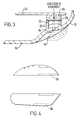
- FIG. 2 there is shown a back cover member 10 of a radiotelephone.
- the back cover member 10 is conveniently moulded from plastics material. It is designed with a great number of formations to house for example a PCB and receive the battery.
- an outlet orifice port 12 for a buzzer ringer.
- the rear surface thereof has a scooped out recess 14.
- the sectional view of Figure 3 illustrates the profile of the scooped out recess 14 in greater detail.
- the audio outlet orifice 12 is located substantially centrally in relation to the scooped out recess 14.
- the wall of the back cover member 10 is indented and follows a smooth inwardly curved 'S' profile.
- the recess 14 has a generally concave configuration that extends lengthwise to define a channelled recess which extends from below the orifice 12 to the edge 16 of the top side surface of the radiotelephone. Accordingly, when the radiotelephone is placed flat on a surface such as a desk or table or in a briefcase the scooped out recess 14 together with the flat surface forms an audio passageway which acts to guide the sound from the orifice 12 out into the surrounding environment.
- the sectional view shows a formation that straddles the audio outlet orifice 12 which extends inwarding from the internal surface of the cover member, formations which from the Figure appear to be a pair of legs 18.
- the annular wall 18 is so constructed that the rim 20 that it presents is a flat ring with a plane substantially parallel to the plane of the radiotelephone. Because the location of the annular wall 18 is in the area of the recessed surface contour, the depth of the annular wall that forms it is graded, being deeper on one side than the other, so as to provide the flat rim surface.
- the PCB 22 from which the buzzer 24 depends is lowered in a vertical axis into the back cover member 10, in such a manner that the buzzer 24 is aligned with the annular wall 18.
- the PCB 22 is fixed in relation to the back cover member 10 by any convenient means such as screws. In this way, the buzzer 24 is fixed in relation to the annular wall 18.
- the buzzer 24 In operation, when the buzzer 24 is activated the buzzer sound will be emitted and emerge from the outlet orifice 12, be transmitted into the scooped recess 14 and outwards away from the radiotelephone.
- the recessed nature of the back cover member ensures that the outlet orifice is not closed when the radiotelephone is on or pressed against a flat surface.
Landscapes
- Engineering & Computer Science (AREA)
- Signal Processing (AREA)
- Telephone Set Structure (AREA)
- Mobile Radio Communication Systems (AREA)
Abstract
A portable radio communication device comprising a housing and a buzzer
that rings on activation to alert a user of an event, the buzzer being disposed
adjacent the inner surface of the housing and next to an audio outlet orifice for
the buzzer provided in the body cover member, wherein the housing has a
channelled recess provided in its outer surface in the area of the audio outlet
orifice.
Description
- The present invention relates to portable radio communication devices, and more particularly to mounting arrangements for ringer buzzers for such devices.
- Ringer buzzers, sometimes simply called buzzers, are the audio transducers in a mobile communication device such as a portable radiotelephone which ring on activation to alert the user of an incoming call or other event. Typically, in the mobile phone a buzzer is mounted directly onto one of the printed circuit boards (PCB's) and once the PCB is assembled in relation to the phone housing the buzzer is located next to an orifice in the housing through which the ringer sound is emitted when the buzzer is activated. The PCB's are mounted in the phone by fixing them into the rear cover member of the housing, for example by screwing them down in the vertical direction. The body or orifice support for the buzzer is provided in the rear face of the cover member and therefore sealing the buzzer against the rear cover in the vertical direction is straight forward because it is brought into alignment with the seal and the orifice in the vertical direction. This is because the sound outlet is at the rear of the phone.
- The drawback of such an arrangement between the buzzer and cover member is that because the sound outlet is on the back face of the phone, if the phone is placed on a table or pushed against the users body, for example in a pocket, then the sound outlet port becomes blocked (either by the surface of the table or the body) and this can seriously effect the buzzer audio output from the phone. This obviously in turn makes it harder for the user to hear the buzzer when it is ringing, which could lead to missed calls.
- One solution that has been used to overcome this problem is to provide the buzzer orifice at the side of the phone. In this way, when a phone is laid flat on a table surface, the buzzer is directed sideways from the phone and is therefore not obstructed. This type of buzzer again is initially mounted on a PCB and the PCB is assembled by lowering it in a vertical direction into the cover member of the phone, with the buzzer being received in a sealing boot of the phone. This arrangement is shown in figure 1 of the accompanying drawings. As is apparent, the buzzer needs to be sealed in a horizontal direction against the side of the phone, while only compressing the parts concerned in a vertical direction. The result is either poor sealing or a clash of the parts as they are slid past one another making assembly difficult.
- Against this background, the present invention seeks to overcome the difficulties with the prior art buzzers outlined above. Accordingly, the present invention provides a portable radio communication device comprising a housing and a buzzer that rings on activation to alert a user of an event, the buzzer being disposed adjacent the inner surface of the housing and next to an audio outlet orifice for the buzzer provided in the body cover member, wherein the housing has a channelled recess provided in its outer surface in the area of the audio outlet orifice.
- By means of the invention, even if the communication apparatus is laid flat on for example a table their will be a duct for allowing the sound produced by the buzzer to be outletted to the surrounding environment. In effect, the duct is defined by the channel recess and the surface of the table. As a result, such communication apparatus would benefit in that the sound of the buzzer would not be obstructed or muffled in such circumstances.
- Furthermore, because the audio outlet orifice is provided in the rear surface of the cover member, sealing of the buzzer can be effected in a vertical direction, i.e. in a plane parallel to PCB mounting.
- The present invention will now be described by way of example with reference to the accompanying drawings in which
- Figure 1 illustrates a prior art arrangement for mounting a buzzer in a radio telephone;
- Figure 2 is a perspective view of a housing cover member incorporating a channelled recess in accordance with the present invention;
- Figure 3 is a side-on sectional view of the buzzer mounting arrangement of the present invention.
-
- Referring initially to Figure 2 there is shown a
back cover member 10 of a radiotelephone. - The
back cover member 10 is conveniently moulded from plastics material. It is designed with a great number of formations to house for example a PCB and receive the battery. Towards the upper end of the rear surface of theback cover member 10 near the corner formed where the top side meets the rear surface but spaced downwards from the topside, there is provided anoutlet orifice port 12 for a buzzer ringer. As is apparent from Figure 2, in the area of theback cover member 10 surrounding theaudio outlet orifice 12, the rear surface thereof has a scooped outrecess 14. The sectional view of Figure 3 illustrates the profile of the scooped outrecess 14 in greater detail. Theaudio outlet orifice 12 is located substantially centrally in relation to the scooped outrecess 14. The wall of theback cover member 10 is indented and follows a smooth inwardly curved 'S' profile. Therecess 14 has a generally concave configuration that extends lengthwise to define a channelled recess which extends from below theorifice 12 to theedge 16 of the top side surface of the radiotelephone. Accordingly, when the radiotelephone is placed flat on a surface such as a desk or table or in a briefcase the scooped out recess 14 together with the flat surface forms an audio passageway which acts to guide the sound from theorifice 12 out into the surrounding environment. - Referring still to Figure 3, the sectional view shows a formation that straddles the
audio outlet orifice 12 which extends inwarding from the internal surface of the cover member, formations which from the Figure appear to be a pair oflegs 18. These however in the preferred embodiment constitute a continuous annular wall. Theannular wall 18 is so constructed that therim 20 that it presents is a flat ring with a plane substantially parallel to the plane of the radiotelephone. Because the location of theannular wall 18 is in the area of the recessed surface contour, the depth of the annular wall that forms it is graded, being deeper on one side than the other, so as to provide the flat rim surface. - During the assembly process the
PCB 22 from which thebuzzer 24 depends, is lowered in a vertical axis into theback cover member 10, in such a manner that thebuzzer 24 is aligned with theannular wall 18. Once thebuzzer 24 is located against therim 20 ofannular wall 18, thePCB 22 is fixed in relation to theback cover member 10 by any convenient means such as screws. In this way, thebuzzer 24 is fixed in relation to theannular wall 18. Sandwiched between the abutting surface of thebuzzer 24 and therim 20 of theannular wall 18 there is provided anannular sealing ring 26, which acoustically seals the buzzer in an outward direction thereby preventing buzzer sound leaking back into the inside of the radiotelephone. Sealing is thereby effected in the direction in which the PCB board and buzzer are assembled into the radiotelephone. - In operation, when the
buzzer 24 is activated the buzzer sound will be emitted and emerge from theoutlet orifice 12, be transmitted into thescooped recess 14 and outwards away from the radiotelephone. The recessed nature of the back cover member ensures that the outlet orifice is not closed when the radiotelephone is on or pressed against a flat surface. - The present invention may be embodied in other specific forms without departing from its essential attributes. Accordingly reference should be made to the appended claims and other general statement's herein rather than to the foregoing specific description as indicating the scope of invention.
- Furthermore, each feature disclosed in this specification (which term includes the claims) and/or shown in the drawings may be incorporated in the invention independently of other disclosed and/or illustrated features. In this regard, the invention includes any novel features or combination of features disclosed herein either explicitly or any generalisation thereof irrespective of whether or not it relates to the claimed invention or mitigates any or all of the problems addressed.
- The appended abstract as filed herewith is included in the specification by reference.
Claims (6)
- A portable radio communication device comprising a housing having an audio outlet orifice for a buzzer and a buzzer disposed on one side of the housing adjacent to the audio outlet orifice and operable to ring on activation so as to alert a user of an event, wherein the other side of the housing in the region of the audio outlet orifice is recessed in relation to the surrounding area of the housing.
- A portable radio communication device according to claim 1, wherein said channelled recess extends to a side of the device.
- A portable radio communication device according to claim 1, wherein said outlet orifice communicates with a channelled recess provided in the outer surface of the housing.
- A portable radio communication device according to any preceding claim, wherein the buzzer is sealed in relation to the housing in the direction in which it is assembled with respect to the housing.
- A portable radio communication device according to claim 4, wherein the buzzer is sealed with respect to an annular wall upstanding from the inner surface of the housing.
- A portable radio communication device according to any preceding claim, wherein the housing comprises an upper cover member and a lower cover member and the buzzer arrangement is configured with respect to the lower cover member, the outlet orifice being provided in the rearward face of the lower cover member.
Applications Claiming Priority (2)
| Application Number | Priority Date | Filing Date | Title |
|---|---|---|---|
| GB9904001A GB2347298B (en) | 1999-02-22 | 1999-02-22 | Radio telephone buzzer |
| GB9904001 | 1999-02-22 |
Publications (1)
| Publication Number | Publication Date |
|---|---|
| EP1032181A2 true EP1032181A2 (en) | 2000-08-30 |
Family
ID=10848241
Family Applications (1)
| Application Number | Title | Priority Date | Filing Date |
|---|---|---|---|
| EP00301073A Withdrawn EP1032181A2 (en) | 1999-02-22 | 2000-02-11 | Radiotelephone buzzer |
Country Status (3)
| Country | Link |
|---|---|
| US (1) | US6697636B1 (en) |
| EP (1) | EP1032181A2 (en) |
| GB (1) | GB2347298B (en) |
Families Citing this family (3)
| Publication number | Priority date | Publication date | Assignee | Title |
|---|---|---|---|---|
| US8971974B2 (en) | 2011-04-28 | 2015-03-03 | Nflukz, Llc | Cover for hand-held electronic device |
| JP2022545039A (en) | 2019-08-24 | 2022-10-24 | スカイベル テクノロジーズ アイピー、エルエルシー | Doorbell communication system and method |
| WO2023129803A1 (en) * | 2021-12-29 | 2023-07-06 | Skybell Technologies Ip, Llc | Doorbell housing |
Family Cites Families (4)
| Publication number | Priority date | Publication date | Assignee | Title |
|---|---|---|---|---|
| JP2616462B2 (en) * | 1994-09-22 | 1997-06-04 | 日本電気株式会社 | Portable radio telephone equipment |
| US5909490A (en) * | 1997-07-07 | 1999-06-01 | Hughes Electronics Corporation | Omnidirectional audio in a communications device |
| AU2550299A (en) * | 1998-02-16 | 1999-08-30 | Soo Hyung Lee | Communication buzzer |
| US6374120B1 (en) * | 1999-02-16 | 2002-04-16 | Denso Corporation | Acoustic guide for audio transducers |
-
1999
- 1999-02-22 GB GB9904001A patent/GB2347298B/en not_active Expired - Fee Related
-
2000
- 2000-02-11 EP EP00301073A patent/EP1032181A2/en not_active Withdrawn
- 2000-02-18 US US09/507,382 patent/US6697636B1/en not_active Expired - Lifetime
Also Published As
| Publication number | Publication date |
|---|---|
| GB2347298B (en) | 2003-04-09 |
| GB2347298A (en) | 2000-08-30 |
| US6697636B1 (en) | 2004-02-24 |
| GB9904001D0 (en) | 1999-04-14 |
Similar Documents
| Publication | Publication Date | Title |
|---|---|---|
| KR100767893B1 (en) | Mobile terminal | |
| US7068782B2 (en) | Communications devices with receiver earpieces and methods therefor | |
| US9124348B2 (en) | Mobile terminal having a microphone sound hole and speaker sound hole disposed on the same plane | |
| US8798306B2 (en) | Communication device and a casing therefor | |
| US5790679A (en) | Communications terminal having a single transducer for handset and handsfree receive functionality | |
| TW361030B (en) | Mobile phone enclosure and sound collection means for mobile phone | |
| JP2005006205A (en) | Mobile terminal | |
| US7505602B2 (en) | Mobile device with improved acoustic porting | |
| US6990197B2 (en) | Hands-free speaker telephone | |
| US6697636B1 (en) | Radio telephone buzzer | |
| EP1244330A2 (en) | An acoustic transducer assembly | |
| US8014836B2 (en) | Telephone apparatus | |
| EP1670219B1 (en) | Electronic device and microphone holder therefor | |
| KR970008983A (en) | Portable Cordless Phone with Improved Handset | |
| CN111818419B (en) | Sound leakage prevention electronic equipment | |
| CA2689173C (en) | Speaker clearance arrangement for a communication device | |
| KR200229974Y1 (en) | anti-noise device for wire & wireless phone | |
| KR100501303B1 (en) | Speaker structure of mobile phone having mulit speaker hole | |
| JP3542498B2 (en) | Sound collection structure | |
| KR100651947B1 (en) | Mobile communication terminal with duct for speaker | |
| KR200187101Y1 (en) | Apparatus for speaker support of telephone | |
| CN112736552A (en) | Waterproof earphone hole and mobile phone | |
| CN201898538U (en) | Mobile phone and shell thereof | |
| KR200218625Y1 (en) | Cell phone and cassette integrated earphone | |
| JP2001127837A (en) | Mobile phone |
Legal Events
| Date | Code | Title | Description |
|---|---|---|---|
| PUAI | Public reference made under article 153(3) epc to a published international application that has entered the european phase |
Free format text: ORIGINAL CODE: 0009012 |
|
| AK | Designated contracting states |
Kind code of ref document: A2 Designated state(s): AT BE CH CY DE DK ES FI FR GB GR IE IT LI LU MC NL PT SE |
|
| AX | Request for extension of the european patent |
Free format text: AL;LT;LV;MK;RO;SI |
|
| RAP1 | Party data changed (applicant data changed or rights of an application transferred) |
Owner name: NOKIA CORPORATION |
|
| STAA | Information on the status of an ep patent application or granted ep patent |
Free format text: STATUS: THE APPLICATION HAS BEEN WITHDRAWN |
|
| 18W | Application withdrawn |
Effective date: 20021211 |