EP1032098A2 - Laser oscillating apparatus - Google Patents
Laser oscillating apparatus Download PDFInfo
- Publication number
- EP1032098A2 EP1032098A2 EP00301521A EP00301521A EP1032098A2 EP 1032098 A2 EP1032098 A2 EP 1032098A2 EP 00301521 A EP00301521 A EP 00301521A EP 00301521 A EP00301521 A EP 00301521A EP 1032098 A2 EP1032098 A2 EP 1032098A2
- Authority
- EP
- European Patent Office
- Prior art keywords
- slot
- laser
- energy
- laser gas
- supplying
- Prior art date
- Legal status (The legal status is an assumption and is not a legal conclusion. Google has not performed a legal analysis and makes no representation as to the accuracy of the status listed.)
- Granted
Links
Images




Classifications
-
- H—ELECTRICITY
- H01—ELECTRIC ELEMENTS
- H01S—DEVICES USING THE PROCESS OF LIGHT AMPLIFICATION BY STIMULATED EMISSION OF RADIATION [LASER] TO AMPLIFY OR GENERATE LIGHT; DEVICES USING STIMULATED EMISSION OF ELECTROMAGNETIC RADIATION IN WAVE RANGES OTHER THAN OPTICAL
- H01S3/00—Lasers, i.e. devices using stimulated emission of electromagnetic radiation in the infrared, visible or ultraviolet wave range
- H01S3/02—Constructional details
- H01S3/03—Constructional details of gas laser discharge tubes
- H01S3/0315—Waveguide lasers
-
- G—PHYSICS
- G03—PHOTOGRAPHY; CINEMATOGRAPHY; ANALOGOUS TECHNIQUES USING WAVES OTHER THAN OPTICAL WAVES; ELECTROGRAPHY; HOLOGRAPHY
- G03F—PHOTOMECHANICAL PRODUCTION OF TEXTURED OR PATTERNED SURFACES, e.g. FOR PRINTING, FOR PROCESSING OF SEMICONDUCTOR DEVICES; MATERIALS THEREFOR; ORIGINALS THEREFOR; APPARATUS SPECIALLY ADAPTED THEREFOR
- G03F7/00—Photomechanical, e.g. photolithographic, production of textured or patterned surfaces, e.g. printing surfaces; Materials therefor, e.g. comprising photoresists; Apparatus specially adapted therefor
- G03F7/70—Microphotolithographic exposure; Apparatus therefor
- G03F7/70383—Direct write, i.e. pattern is written directly without the use of a mask by one or multiple beams
-
- H—ELECTRICITY
- H01—ELECTRIC ELEMENTS
- H01S—DEVICES USING THE PROCESS OF LIGHT AMPLIFICATION BY STIMULATED EMISSION OF RADIATION [LASER] TO AMPLIFY OR GENERATE LIGHT; DEVICES USING STIMULATED EMISSION OF ELECTROMAGNETIC RADIATION IN WAVE RANGES OTHER THAN OPTICAL
- H01S3/00—Lasers, i.e. devices using stimulated emission of electromagnetic radiation in the infrared, visible or ultraviolet wave range
- H01S3/02—Constructional details
- H01S3/03—Constructional details of gas laser discharge tubes
- H01S3/038—Electrodes, e.g. special shape, configuration or composition
- H01S3/0385—Shape
-
- H—ELECTRICITY
- H01—ELECTRIC ELEMENTS
- H01S—DEVICES USING THE PROCESS OF LIGHT AMPLIFICATION BY STIMULATED EMISSION OF RADIATION [LASER] TO AMPLIFY OR GENERATE LIGHT; DEVICES USING STIMULATED EMISSION OF ELECTROMAGNETIC RADIATION IN WAVE RANGES OTHER THAN OPTICAL
- H01S3/00—Lasers, i.e. devices using stimulated emission of electromagnetic radiation in the infrared, visible or ultraviolet wave range
- H01S3/09—Processes or apparatus for excitation, e.g. pumping
- H01S3/097—Processes or apparatus for excitation, e.g. pumping by gas discharge of a gas laser
- H01S3/0975—Processes or apparatus for excitation, e.g. pumping by gas discharge of a gas laser using inductive or capacitive excitation
-
- H—ELECTRICITY
- H01—ELECTRIC ELEMENTS
- H01S—DEVICES USING THE PROCESS OF LIGHT AMPLIFICATION BY STIMULATED EMISSION OF RADIATION [LASER] TO AMPLIFY OR GENERATE LIGHT; DEVICES USING STIMULATED EMISSION OF ELECTROMAGNETIC RADIATION IN WAVE RANGES OTHER THAN OPTICAL
- H01S3/00—Lasers, i.e. devices using stimulated emission of electromagnetic radiation in the infrared, visible or ultraviolet wave range
- H01S3/14—Lasers, i.e. devices using stimulated emission of electromagnetic radiation in the infrared, visible or ultraviolet wave range characterised by the material used as the active medium
- H01S3/22—Gases
- H01S3/223—Gases the active gas being polyatomic, i.e. containing two or more atoms
- H01S3/225—Gases the active gas being polyatomic, i.e. containing two or more atoms comprising an excimer or exciplex
Definitions
- excimer laser oscillator uses this light to amplify as an in-phase beam in an optical resonator constructed of a pair of reflecting mirrors and extract as a laser beam.
- microwaves are used as a laser gas exciting source.
- Microwaves are electromagnetic waves having an oscillation frequency of a few hundred MHz to several tens of GHz.
- a microwave is introduced from a waveguide into a laser tube through a slot formed in the waveguide wall, thereby exciting a laser gas in the laser tube into a plasma.
- the energy supplying portion preferably ionizes the laser gas by supplying energy to the laser gas using the electrode.
- the energy supplying portion include, near the slot, a plurality of electrode pairs for supplying energy to the laser gas, and a current with a current density higher than a current density of a current supplied between the electrode pair near a central portion of the slot be supplied between the electrode pair near an end portion of the slot.
- the energy supplying portion include, near the slot, a plurality of electrode pairs for supplying energy to the laser gas, and the plurality of electrode pairs concentrate near an end portion of the slot.
- the energy supplying portion include, near the slot, a plurality of electrode pairs for supplying energy to the laser gas, and the electrode pair near an end portion of the slot be located nearer to the slot than the electrode pair near a central portion of the slot.
- the energy supplying portion preferably includes a light source for irradiating a portion near the slot with light.
- the surface of the waveguide in which the window is preferably formed opposes a surface of the waveguide in which the slot is formed.
- an exposure apparatus including a laser oscillating unit, an illumination optical system for generating illuminating light for illuminating a mask by using a laser light supplied from the laser oscillating unit, and a projection optical system for projecting a pattern of the mask illuminated with the illuminating light generated by the optical system onto a substrate, characterized in that the laser oscillating unit generates the laser beam by introducing an electromagnetic wave into a laser tube filled with a laser gas through a slot formed in a waveguide wall, and the unit comprises an energy supplying portion for supplying energy to the laser gas to control an excited state distribution of the laser gas independently of introducing the electromagnetic wave into the laser tube through the slot.
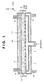
- this excimer laser oscillator includes a laser tube 2, waveguide 1, and cooling vessel 7.
- the laser tube 2 emits a laser beam by resonating light generated by the excitation of an excimer laser gas.
- the waveguide 1 excites the excimer laser gas in the laser tube 2 to generate a plasma.
- the cooling vessel 7 has cooling water inlet/output ports 9 for cooling the waveguide 1.
- the excimer laser gas as a material for generating an excimer laser beam is at least one inert gas selected from Kr, Ar, Ne, and He or a gas mixture of at least one inert gas described above and F 2 gas. These gases can be appropriately selected and used in accordance with the wavelength of interest.
- Figs. 3A to 3C show examples of the arrangement of electrodes 13 formed around an arbitrary slot 10.
- the electrodes 13 are used to ionize a laser gas before microwaves are supplied.
- Fig. 3A shows an example of the arrangement of six electrodes around the slot 10.
- Fig. 7B is a sectional view taken along a direction perpendicular to the longitudinal direction of a bend waveguide 21'.
- a UV transmission window 21'a is formed in an inclined surface 21'b to allow direct UV irradiation from a position opposing the slot 10 as in the case of the waveguide 21 in Fig. 7A.
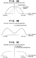
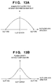
- Fig. 9C shows the laser gas (plasma density) excited by a microwave radiated from the slot 10 when the UV irradiation shown in Fig. 9B is performed.
- excitation of the laser gas at each end portion of the slot 10 in the longitudinal direction in particular, can be promoted.
- a laser gas excitation state (plasma density) in the entire region of the slot 10 can be uniformized.
- the UV light sources 22 are arranged to concentrate UV irradiation on the end portions of the slots 10 in the longitudinal direction, excitation of the laser gas at the end portions of the slots 10, at which the laser gas is not readily excited, can be promoted by UV irradiation.
- This makes it possible to uniformize excitation of the laser gas at the central portion and end portions of each slot 10 in the longitudinal direction, thus uniformly exciting the laser gas in the entire range on each slot 10.
- the same effect as described above can be obtained by using X-ray or RF (Radio Frequency) preionization instead of UV irradiation.
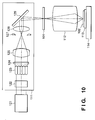
- Fig. 10 is a schematic view showing the main components of this stepper.
- the illumination optical system 111 includes an excimer laser oscillator 121 of the first embodiment, beam shape converter 122, optical integrator 123, stop member 124, condenser lens 125, blind 127, image forming lens 128, and reflecting mirror 129.
- the excimer laser oscillator 121 is a light source for emitting a high-luminance excimer laser beam as illuminating light.
- the beam shape converter 122 converts the illuminating light from the light source 121 into a beam having a desired sectional shape.
- the optical integrator 123 is formed by two-dimensionally arranging a plurality of cylindrical lenses or microlenses.
- the stop member 124 is placed near the position of secondary sources formed by the optical integrator 123 and can be switched to an arbitrary aperture value by a switching mechanism (not shown).
- the condenser lens 125 condenses the illuminating light passing through the stop member 124.
- the blind 127 is constructed of, e.g., four variable blades and placed on the conjugate plane of the reticle 101 to determine an arbitrary illuminating range on the surface of the reticle 101.
- the image forming lens 128 projects the illuminating light formed into a predetermined shape by the blind 127 onto the surface of the reticle 101.
- the reflecting mirror 129 reflects the illuminating light from the image forming lens 128 toward the reticle 101.
Landscapes
- Physics & Mathematics (AREA)
- Electromagnetism (AREA)
- Engineering & Computer Science (AREA)
- Plasma & Fusion (AREA)
- Optics & Photonics (AREA)
- General Physics & Mathematics (AREA)
- Lasers (AREA)
- Exposure And Positioning Against Photoresist Photosensitive Materials (AREA)
- Exposure Of Semiconductors, Excluding Electron Or Ion Beam Exposure (AREA)
Abstract
Description
Claims (26)
- A laser oscillating apparatus for generating a laser beam by introducing an electromagnetic wave into a laser tube (2) filled with a laser gas through a slot (10) formed in a waveguide wall (1) characterized by comprising
an energy supplying portion (13) for supplying energy to the laser gas to control an excited state distribution (Fig. 5C) of the laser gas independently of introducing the electromagnetic wave into said laser tube (2) through said slot (10). - The apparatus according to claim 1, characterized in that said energy supplying portion (13) supplies energy to the laser gas so as to substantially uniformly excite the laser gas along said slot (10).
- The apparatus according to claim 1 or 2, characterized in that said energy supplying portion includes, near said slot, an electrode (13) for supplying energy to the laser gas.
- The apparatus according to claim 3, characterized in that said energy supplying portion ionizes the laser gas by supplying energy to the laser gas using said electrode (13).
- The apparatus according to any one of claims 1 to 4, characterized in that said energy supplying portion preliminarily ionizes the laser gas before supplying an electromagnetic wave through said waveguide (1).
- The apparatus according to any one of claims 3 to 5, characterized in that said electrode (13) supplies energy to the laser gas to make an ionization density near an end portion of said slot (10) higher than an ionization density near a central portion of said slot (10) (Fig. 3B).
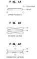
- The apparatus according to claim 1 or 2, characterized in that said energy supplying portion includes, near said slot, at least one pair of electrodes (13) for supplying energy to the laser gas, and said at least one pair of electrodes (13) are arranged to make an ionization density near an end portion of said slot (10) higher than an ionization density near a central portion of said slot (10) (Figs. 3C, 4A, 4B, 4C).
- The apparatus according to claim 1 or 2, characterized in that said energy supplying portion includes at least one pair of electrodes (13) for supplying energy to the laser gas, and said at least one pair of electrodes (13) are shaped to make an ionization density near an end portion of said slot (10) higher than an ionization density near a central portion of said slot (10) (Fig. 4B).
- The apparatus according to claim 1 or 2, characterized in that said energy supplying portion includes, near said slot (10), a plurality of electrode pairs (13) for supplying energy to the laser gas, and a current with a current density higher than a current density of a current supplied between said electrode pair (13) near a central portion of said slot (13) is supplied between said electrode pair (13) near an end portion of said slot (10) (Fig. 3B).
- The apparatus according to claim 1 or 2, characterized in that said energy supplying portion includes, near said slot (10), a plurality of electrode pairs (13) for supplying energy to the laser gas, and said plurality of electrode pairs (13) concentrate near an end portion of said slot (10) (Fig. 3C).
- The apparatus according to claim 1 or 2, characterized in that said energy supplying portion includes, along said slot (10), one pair of electrodes (13) for supplying energy to the laser gas, and each of said pair of electrode is wider near an end portion of said slot (10) than near a central portion of said slot (10) (Fig. 4B).
- The apparatus according to claim 1 or 2, characterized in that said energy supplying portion includes, near said slot (10), a plurality of electrode pairs (13) for supplying energy to the laser gas, and said electrode pair (13) near an end portion of said slot (10) is located nearer to said slot (10) than said electrode pair (13) near a central portion of said slot (10) (Fig. 4C).
- The apparatus according to any one of claims 1 to 6, characterized in that said energy supplying portion supplies energy to the laser gas to make an ionization density near an end portion of said slot (10) higher than an ionization density near a central portion of said slot (10) .
- The apparatus according to claim 1 or 2, characterized in that said energy supplying portion includes a light source (22) for irradiating a portion near said slot (10) with light.
- The apparatus according to claim 14, characterized in that said waveguide (21) is placed between said light source (22) and said laser tube (2), and one surface of said waveguide (21) has a window (21a) transmitting light form said light source (22).
- The apparatus according to claim 15, characterized in that the surface of said waveguide (21) in which said window (21a) is formed opposes a surface of said waveguide (21) in which said slot (10) is formed.
- The apparatus according to claim 15 or 16, characterized in that said window (21a) has a size that disables the electromagnetic wave from passing through.
- The apparatus according to any one of claims 14 to 17, characterized in that said energy supplying portion further includes a reflecting mirror (23) for reflecting light from said light source (22) toward a portion near said slot (10).
- The apparatus according to any one of claims 14 to 18, characterized in that said light source (22) generate ultraviolet light.
- The apparatus according to any one of claims 1 to 19, characterized in that said plurality of slots (10) are formed in said waveguide (1).
- The apparatus according to claim 20, characterized in that said plurality of slots (10) are formed along a longitudinal direction of said waveguide.
- The apparatus according to claim 20 or 21, characterized in that said energy supplying portion (13) is provided for each slot (10).
- An exposure apparatus including a laser oscillating unit, an illumination optical system for generating illuminating light for illuminating a mask by using a laser light supplied from said laser oscillating unit, and a projection optical system for projecting a pattern of the mask illuminated with the illuminating light generated by said optical system onto a substrate,
characterized in that said laser oscillating unit generates the laser beam by introducing an electromagnetic wave into a laser tube (2) filled with a laser gas through a slot (10) formed in a waveguide wall (1), and
said unit comprises an energy supplying portion (13) for supplying energy to the laser gas to control an excited state distribution (Fig. 5C) of the laser gas independently of introducing the electromagnetic wave into said laser tube (2) through said slot (10). - A device manufacturing method characterized by comprising the steps of:coating a substrate with a photosensitive material;exposing a pattern on the substrate coated with the photosensitive material by using said exposure apparatus defined in claim 23;developing the pattern on the exposed substrate; andfabricating a device from the exposed substrate.
- An exposure apparatus comprising a laser oscillating apparatus, an illumination optical system for generating illuminating light for illuminating a mask by using illuminating light supplied from said laser oscillating unit, and a projection optical system for projecting a pattern of the mask illuminated with the illuminating light generated by said optical system onto a substrate,
characterized in that said laser oscillating apparatus is said laser oscillating apparatus defined in any one of claims 1 to 22. - A device manufacturing method characterized by comprising the steps of:coating a substrate with a photosensitive material;exposing a pattern on the substrate coated with the photosensitive material by using said exposure apparatus defined in claim 25;developing the pattern on the exposed substrate; andfabricating a device from the exposed substrate.
Applications Claiming Priority (2)
| Application Number | Priority Date | Filing Date | Title |
|---|---|---|---|
| JP5181499 | 1999-02-26 | ||
| JP05181499A JP4256520B2 (en) | 1999-02-26 | 1999-02-26 | Laser oscillation apparatus, exposure apparatus, and device manufacturing method |
Publications (3)
| Publication Number | Publication Date |
|---|---|
| EP1032098A2 true EP1032098A2 (en) | 2000-08-30 |
| EP1032098A3 EP1032098A3 (en) | 2001-09-12 |
| EP1032098B1 EP1032098B1 (en) | 2004-06-09 |
Family
ID=12897383
Family Applications (1)
| Application Number | Title | Priority Date | Filing Date |
|---|---|---|---|
| EP00301521A Expired - Lifetime EP1032098B1 (en) | 1999-02-26 | 2000-02-25 | Laser oscillating apparatus |
Country Status (4)
| Country | Link |
|---|---|
| US (1) | US6650678B1 (en) |
| EP (1) | EP1032098B1 (en) |
| JP (1) | JP4256520B2 (en) |
| DE (1) | DE60011322T2 (en) |
Cited By (1)
| Publication number | Priority date | Publication date | Assignee | Title |
|---|---|---|---|---|
| US6795167B2 (en) | 2000-11-10 | 2004-09-21 | Canon Kabushiki Kaisha | Projection exposure apparatus and device manufacturing method using the same |
Families Citing this family (2)
| Publication number | Priority date | Publication date | Assignee | Title |
|---|---|---|---|---|
| EP1026796B1 (en) * | 1999-02-01 | 2005-11-16 | Tadahiro Ohmi | Laser oscillating apparatus, exposure apparatus using the same, and device fabrication method |
| EP1361606B1 (en) * | 2001-01-25 | 2010-11-24 | Tokyo Electron Limited | Method of producing electronic device material |
Family Cites Families (15)
| Publication number | Priority date | Publication date | Assignee | Title |
|---|---|---|---|---|
| US4004249A (en) * | 1976-01-22 | 1977-01-18 | General Motors Corporation | Optical waveguide laser pumped by guided electromagnetic wave |
| US4802183A (en) * | 1982-04-07 | 1989-01-31 | Board Of Trustees Of The Leland Stanford Junior University | Microwave excited excimer laser and method |
| US4513424A (en) * | 1982-09-21 | 1985-04-23 | Waynant Ronald W | Laser pumped by X-band microwaves |
| DE3912568A1 (en) * | 1989-04-17 | 1990-10-18 | Siemens Ag | GAS LASER, ESPECIALLY CO (DOWN ARROW) 2 (DOWN ARROW) LASER |
| DE4112946A1 (en) * | 1991-04-20 | 1992-10-22 | Deutsche Forsch Luft Raumfahrt | PULSE GAS DISCHARGE LASER SYSTEM |
| US5255282A (en) * | 1991-11-25 | 1993-10-19 | Quantametrics Inc. | Open waveguide excimer laser |
| US5450436A (en) * | 1992-11-20 | 1995-09-12 | Kabushiki Kaisha Komatsu Seisakusho | Laser gas replenishing apparatus and method in excimer laser system |
| JP3382314B2 (en) | 1993-08-24 | 2003-03-04 | キヤノン株式会社 | Communication device and communication device control method |
| US5900103A (en) * | 1994-04-20 | 1999-05-04 | Tokyo Electron Limited | Plasma treatment method and apparatus |
| JP2816813B2 (en) * | 1994-04-12 | 1998-10-27 | 株式会社小松製作所 | Excimer laser device |
| JPH08220304A (en) * | 1995-02-13 | 1996-08-30 | Tadahiro Omi | Optical article, exposure apparatus or optical system using the same, and method of manufacturing the same |
| US5696428A (en) * | 1995-06-07 | 1997-12-09 | Lsi Logic Corporation | Apparatus and method using optical energy for specifying and quantitatively controlling chemically-reactive components of semiconductor processing plasma etching gas |
| US6331994B1 (en) | 1996-07-19 | 2001-12-18 | Canon Kabushiki Kaisha | Excimer laser oscillation apparatus and method, excimer laser exposure apparatus, and laser tube |
| JP3815578B2 (en) * | 1996-07-19 | 2006-08-30 | 忠弘 大見 | Excimer laser oscillator |
| WO1998033362A1 (en) * | 1997-01-29 | 1998-07-30 | Tadahiro Ohmi | Plasma device |
-
1999
- 1999-02-26 JP JP05181499A patent/JP4256520B2/en not_active Expired - Lifetime
-
2000
- 2000-02-24 US US09/512,075 patent/US6650678B1/en not_active Expired - Lifetime
- 2000-02-25 EP EP00301521A patent/EP1032098B1/en not_active Expired - Lifetime
- 2000-02-25 DE DE60011322T patent/DE60011322T2/en not_active Expired - Lifetime
Cited By (1)
| Publication number | Priority date | Publication date | Assignee | Title |
|---|---|---|---|---|
| US6795167B2 (en) | 2000-11-10 | 2004-09-21 | Canon Kabushiki Kaisha | Projection exposure apparatus and device manufacturing method using the same |
Also Published As
| Publication number | Publication date |
|---|---|
| JP4256520B2 (en) | 2009-04-22 |
| EP1032098A3 (en) | 2001-09-12 |
| US6650678B1 (en) | 2003-11-18 |
| EP1032098B1 (en) | 2004-06-09 |
| DE60011322T2 (en) | 2005-06-23 |
| DE60011322D1 (en) | 2004-07-15 |
| JP2000252565A (en) | 2000-09-14 |
Similar Documents
| Publication | Publication Date | Title |
|---|---|---|
| KR100349015B1 (en) | Excimer laser oscillation apparatus and method, excimer laser exposure apparatus, and laser tube | |
| EP0066053B1 (en) | Apparatus for, and method of, exposing a photosensitive medium to light | |
| JP2002006096A (en) | Electromagnetic wave generator, semiconductor manufacturing apparatus and semiconductor device manufacturing method using the same | |
| US6690702B1 (en) | Excimer laser oscillation apparatus and method, excimer laser exposure apparatus, and laser tube | |
| US6829279B1 (en) | Laser oscillating apparatus, exposure apparatus using the same and device fabrication method | |
| US6744802B1 (en) | Laser oscillating apparatus with slotted waveguide | |
| EP1032098B1 (en) | Laser oscillating apparatus | |
| JPH10163547A (en) | Continuous emission excimer laser oscillation apparatus and oscillation method, exposure apparatus, and laser tube | |
| EP1039595B1 (en) | Gas laser | |
| JP4204689B2 (en) | Laser oscillation apparatus, exposure apparatus, and device manufacturing method | |
| JP4256519B2 (en) | Laser oscillation apparatus, exposure apparatus, and device manufacturing method | |
| US6885015B2 (en) | Thermionic-cathode for pre-ionization of an extreme ultraviolet (EUV) source supply | |
| JP4256518B2 (en) | Laser oscillation apparatus, exposure apparatus, and device manufacturing method | |
| JP4295855B2 (en) | Laser oscillation apparatus, exposure apparatus, and device manufacturing method | |
| JP4302810B2 (en) | Laser oscillation apparatus, exposure apparatus, and device manufacturing method | |
| US20040183486A1 (en) | Extreme ultraviolet transition oscillator | |
| JP2000252563A (en) | Laser oscillation apparatus, exposure apparatus, and device manufacturing method | |
| US20250364769A1 (en) | Laser chamber apparatus, gas laser apparatus, and electronic device manufacturing method | |
| JPH10163553A (en) | Continuous emission excimer laser oscillation apparatus and oscillation method, exposure apparatus, and laser tube | |
| KR20040020585A (en) | extreme ultraviolet generator using plasma reactor | |
| JPH11354862A (en) | Device and method for oscillating excimer laser, aligner, and laser tube | |
| JPH11204857A (en) | Excimer laser oscillation device and oscillation method, exposure apparatus and laser tube | |
| JPH11168264A (en) | Exposure method, exposure apparatus, and method of manufacturing semiconductor integrated circuit device | |
| JPH0612755B2 (en) | Exposure equipment |
Legal Events
| Date | Code | Title | Description |
|---|---|---|---|
| PUAI | Public reference made under article 153(3) epc to a published international application that has entered the european phase |
Free format text: ORIGINAL CODE: 0009012 |
|
| AK | Designated contracting states |
Kind code of ref document: A2 Designated state(s): DE GB NL Kind code of ref document: A2 Designated state(s): AT BE CH CY DE DK ES FI FR GB GR IE IT LI LU MC NL PT SE |
|
| AX | Request for extension of the european patent |
Free format text: AL;LT;LV;MK;RO;SI |
|
| PUAL | Search report despatched |
Free format text: ORIGINAL CODE: 0009013 |
|
| AK | Designated contracting states |
Kind code of ref document: A3 Designated state(s): AT BE CH CY DE DK ES FI FR GB GR IE IT LI LU MC NL PT SE |
|
| AX | Request for extension of the european patent |
Free format text: AL;LT;LV;MK;RO;SI |
|
| 17P | Request for examination filed |
Effective date: 20020128 |
|
| 17Q | First examination report despatched |
Effective date: 20020423 |
|
| AKX | Designation fees paid |
Free format text: DE GB NL |
|
| GRAP | Despatch of communication of intention to grant a patent |
Free format text: ORIGINAL CODE: EPIDOSNIGR1 |
|
| RIN1 | Information on inventor provided before grant (corrected) |
Inventor name: SUZUKI, NOBUMASA,C/O CANON KABUSHIKI KAISHA Inventor name: SHINOHARA, TOSHIKUNI,C/O CANON KABUSHIKI KAISHA Inventor name: TANAKA, NOBUYOSHIC/O CANON KABUSHIKI KAISHA Inventor name: OHMI, TADAHIRO Inventor name: OHSAWA, HIROSHI,C/O CANON KABUSHIKI KAISHA Inventor name: HIRAYAMA, MASAKI,C/O CANON KABUSHIKI KAISHA |
|
| RIN1 | Information on inventor provided before grant (corrected) |
Inventor name: HIRAYAMA, MASAKI Inventor name: SHINOHARA, TOSHIKUNI Inventor name: TANAKA, NOBUYOSHIC/O CANON KABUSHIKI KAISHA Inventor name: OHSAWA, HIROSHI,C/O CANON KABUSHIKI KAISHA Inventor name: OHMI, TADAHIRO Inventor name: SUZUKI, NOBUMASA,C/O CANON KABUSHIKI KAISHA |
|
| GRAS | Grant fee paid |
Free format text: ORIGINAL CODE: EPIDOSNIGR3 |
|
| GRAA | (expected) grant |
Free format text: ORIGINAL CODE: 0009210 |
|
| AK | Designated contracting states |
Kind code of ref document: B1 Designated state(s): DE GB NL |
|
| REG | Reference to a national code |
Ref country code: GB Ref legal event code: FG4D |
|
| RIN1 | Information on inventor provided before grant (corrected) |
Inventor name: SHINOHARA, TOSHIKUNI Inventor name: TANAKA, NOBUYOSHIC/O CANON KABUSHIKI KAISHA Inventor name: SUZUKI, NOBUMASA,C/O CANON KABUSHIKI KAISHA Inventor name: OHMI, TADAHIRO Inventor name: OHSAWA, HIROSHI,C/O CANON KABUSHIKI KAISHA Inventor name: HIRAYAMA, MASAKI |
|
| REF | Corresponds to: |
Ref document number: 60011322 Country of ref document: DE Date of ref document: 20040715 Kind code of ref document: P |
|
| PLBE | No opposition filed within time limit |
Free format text: ORIGINAL CODE: 0009261 |
|
| STAA | Information on the status of an ep patent application or granted ep patent |
Free format text: STATUS: NO OPPOSITION FILED WITHIN TIME LIMIT |
|
| 26N | No opposition filed |
Effective date: 20050310 |
|
| PGFP | Annual fee paid to national office [announced via postgrant information from national office to epo] |
Ref country code: DE Payment date: 20190212 Year of fee payment: 20 Ref country code: NL Payment date: 20190116 Year of fee payment: 20 Ref country code: GB Payment date: 20190220 Year of fee payment: 20 |
|
| REG | Reference to a national code |
Ref country code: DE Ref legal event code: R071 Ref document number: 60011322 Country of ref document: DE |
|
| REG | Reference to a national code |
Ref country code: NL Ref legal event code: MK Effective date: 20200224 |
|
| REG | Reference to a national code |
Ref country code: GB Ref legal event code: PE20 Expiry date: 20200224 |
|
| PG25 | Lapsed in a contracting state [announced via postgrant information from national office to epo] |
Ref country code: GB Free format text: LAPSE BECAUSE OF EXPIRATION OF PROTECTION Effective date: 20200224 |