EP1032060A1 - Battery pack - Google Patents
Battery pack Download PDFInfo
- Publication number
- EP1032060A1 EP1032060A1 EP00103535A EP00103535A EP1032060A1 EP 1032060 A1 EP1032060 A1 EP 1032060A1 EP 00103535 A EP00103535 A EP 00103535A EP 00103535 A EP00103535 A EP 00103535A EP 1032060 A1 EP1032060 A1 EP 1032060A1
- Authority
- EP
- European Patent Office
- Prior art keywords
- battery pack
- terminal
- recited
- protective component
- sealing plate
- Prior art date
- Legal status (The legal status is an assumption and is not a legal conclusion. Google has not performed a legal analysis and makes no representation as to the accuracy of the status listed.)
- Granted
Links
- 230000001681 protective effect Effects 0.000 claims abstract description 83
- 238000007789 sealing Methods 0.000 claims abstract description 53
- 239000011810 insulating material Substances 0.000 claims abstract description 4
- 230000002745 absorbent Effects 0.000 claims description 31
- 239000002250 absorbent Substances 0.000 claims description 31
- 239000000463 material Substances 0.000 claims description 31
- 239000003792 electrolyte Substances 0.000 claims description 24
- 238000004321 preservation Methods 0.000 claims description 23
- 239000010408 film Substances 0.000 claims description 4
- 238000005192 partition Methods 0.000 claims description 4
- 239000004033 plastic Substances 0.000 claims description 4
- 239000010409 thin film Substances 0.000 claims description 4
- 230000000149 penetrating effect Effects 0.000 claims description 3
- 239000000835 fiber Substances 0.000 claims description 2
- 239000004745 nonwoven fabric Substances 0.000 claims description 2
- 239000002984 plastic foam Substances 0.000 claims description 2
- 239000002184 metal Substances 0.000 claims 1
- 239000007789 gas Substances 0.000 description 10
- 238000003466 welding Methods 0.000 description 8
- 230000006378 damage Effects 0.000 description 5
- 230000007257 malfunction Effects 0.000 description 3
- 229920006257 Heat-shrinkable film Polymers 0.000 description 2
- XEEYBQQBJWHFJM-UHFFFAOYSA-N Iron Chemical compound [Fe] XEEYBQQBJWHFJM-UHFFFAOYSA-N 0.000 description 2
- PXHVJJICTQNCMI-UHFFFAOYSA-N Nickel Chemical compound [Ni] PXHVJJICTQNCMI-UHFFFAOYSA-N 0.000 description 2
- 230000002159 abnormal effect Effects 0.000 description 2
- 239000000853 adhesive Substances 0.000 description 2
- 230000001070 adhesive effect Effects 0.000 description 2
- 238000003780 insertion Methods 0.000 description 2
- 230000037431 insertion Effects 0.000 description 2
- WABPQHHGFIMREM-UHFFFAOYSA-N lead(0) Chemical compound [Pb] WABPQHHGFIMREM-UHFFFAOYSA-N 0.000 description 2
- 230000002093 peripheral effect Effects 0.000 description 2
- 229910000838 Al alloy Inorganic materials 0.000 description 1
- 235000009854 Cucurbita moschata Nutrition 0.000 description 1
- 240000001980 Cucurbita pepo Species 0.000 description 1
- 235000009852 Cucurbita pepo Nutrition 0.000 description 1
- UFHFLCQGNIYNRP-UHFFFAOYSA-N Hydrogen Chemical compound [H][H] UFHFLCQGNIYNRP-UHFFFAOYSA-N 0.000 description 1
- HBBGRARXTFLTSG-UHFFFAOYSA-N Lithium ion Chemical compound [Li+] HBBGRARXTFLTSG-UHFFFAOYSA-N 0.000 description 1
- 238000010521 absorption reaction Methods 0.000 description 1
- 239000002313 adhesive film Substances 0.000 description 1
- XAGFODPZIPBFFR-UHFFFAOYSA-N aluminium Chemical compound [Al] XAGFODPZIPBFFR-UHFFFAOYSA-N 0.000 description 1
- 229910052782 aluminium Inorganic materials 0.000 description 1
- OJIJEKBXJYRIBZ-UHFFFAOYSA-N cadmium nickel Chemical compound [Ni].[Cd] OJIJEKBXJYRIBZ-UHFFFAOYSA-N 0.000 description 1
- 238000003776 cleavage reaction Methods 0.000 description 1
- 230000007797 corrosion Effects 0.000 description 1
- 238000005260 corrosion Methods 0.000 description 1
- 239000008151 electrolyte solution Substances 0.000 description 1
- 238000004880 explosion Methods 0.000 description 1
- 239000001257 hydrogen Substances 0.000 description 1
- 229910052739 hydrogen Inorganic materials 0.000 description 1
- 229910052742 iron Inorganic materials 0.000 description 1
- 229910001416 lithium ion Inorganic materials 0.000 description 1
- 238000013508 migration Methods 0.000 description 1
- 230000005012 migration Effects 0.000 description 1
- 229910052759 nickel Inorganic materials 0.000 description 1
- 238000012856 packing Methods 0.000 description 1
- 230000035515 penetration Effects 0.000 description 1
- 230000007017 scission Effects 0.000 description 1
- 235000020354 squash Nutrition 0.000 description 1
Images



Classifications
-
- H—ELECTRICITY
- H01—ELECTRIC ELEMENTS
- H01M—PROCESSES OR MEANS, e.g. BATTERIES, FOR THE DIRECT CONVERSION OF CHEMICAL ENERGY INTO ELECTRICAL ENERGY
- H01M50/00—Constructional details or processes of manufacture of the non-active parts of electrochemical cells other than fuel cells, e.g. hybrid cells
- H01M50/50—Current conducting connections for cells or batteries
- H01M50/572—Means for preventing undesired use or discharge
-
- H—ELECTRICITY
- H01—ELECTRIC ELEMENTS
- H01M—PROCESSES OR MEANS, e.g. BATTERIES, FOR THE DIRECT CONVERSION OF CHEMICAL ENERGY INTO ELECTRICAL ENERGY
- H01M50/00—Constructional details or processes of manufacture of the non-active parts of electrochemical cells other than fuel cells, e.g. hybrid cells
- H01M50/50—Current conducting connections for cells or batteries
- H01M50/572—Means for preventing undesired use or discharge
- H01M50/574—Devices or arrangements for the interruption of current
- H01M50/581—Devices or arrangements for the interruption of current in response to temperature
-
- H—ELECTRICITY
- H01—ELECTRIC ELEMENTS
- H01M—PROCESSES OR MEANS, e.g. BATTERIES, FOR THE DIRECT CONVERSION OF CHEMICAL ENERGY INTO ELECTRICAL ENERGY
- H01M2200/00—Safety devices for primary or secondary batteries
- H01M2200/10—Temperature sensitive devices
- H01M2200/106—PTC
-
- H—ELECTRICITY
- H01—ELECTRIC ELEMENTS
- H01M—PROCESSES OR MEANS, e.g. BATTERIES, FOR THE DIRECT CONVERSION OF CHEMICAL ENERGY INTO ELECTRICAL ENERGY
- H01M50/00—Constructional details or processes of manufacture of the non-active parts of electrochemical cells other than fuel cells, e.g. hybrid cells
- H01M50/50—Current conducting connections for cells or batteries
- H01M50/572—Means for preventing undesired use or discharge
- H01M50/574—Devices or arrangements for the interruption of current
- H01M50/583—Devices or arrangements for the interruption of current in response to current, e.g. fuses
-
- Y—GENERAL TAGGING OF NEW TECHNOLOGICAL DEVELOPMENTS; GENERAL TAGGING OF CROSS-SECTIONAL TECHNOLOGIES SPANNING OVER SEVERAL SECTIONS OF THE IPC; TECHNICAL SUBJECTS COVERED BY FORMER USPC CROSS-REFERENCE ART COLLECTIONS [XRACs] AND DIGESTS
- Y02—TECHNOLOGIES OR APPLICATIONS FOR MITIGATION OR ADAPTATION AGAINST CLIMATE CHANGE
- Y02E—REDUCTION OF GREENHOUSE GAS [GHG] EMISSIONS, RELATED TO ENERGY GENERATION, TRANSMISSION OR DISTRIBUTION
- Y02E60/00—Enabling technologies; Technologies with a potential or indirect contribution to GHG emissions mitigation
- Y02E60/10—Energy storage using batteries
Definitions
- the present invention relates to a battery pack including a protective component such as a thermal fuse or a PTC.
- a battery pack includes a protective component to avoid its use under abnormal conditions.
- the protective component cuts the electric current off if the temperature of the battery raises abnormally high or the current is abnormally high.
- a thermal fuse or a PTC is used as this type of protective component.
- a thermal fuse does blowout so the current is cut if the battery temperature go higher than a predetermined temperature.
- a PTC raises its electrical resistance rapidly so the current hardly flow if the temperature raises due to a high current.
- a battery pack with built-in plural cylindrical batteries includes a built-in protective component 103 at the space between batteries 124 in a case 125.
- the protective component 103 can be built-in using the cleavage space between the cylindrical batteries efficiently.
- a battery pack with built-in rectangular batteries as shown in Fig. 2
- a protective component 203 for the batteries 224 being provided on the printed circuit board 226.
- the battery pack with the structure as shown in Fig. 2 requires larger size of the case 225, since it needs an extra space for providing the built-in protective component 203. In addition, it is difficult to fix the printed circuit board 226 and the protective component 203 at predetermined position between the case 225 and the battery 224 without displacing them. In case that the printed circuit board 226 or the protective component 203 move inside of the case 225, it would deteriorate the reliability, because its vibrations might cause malfunction. Furthermore, as shown in Fig. 2, the battery pack providing the protective component 203 between the side of the battery 224 and the case 225 make the protective component 203 apart from a terminal 208 of a sealing plate 205. Consequently the connection of the protective component 203 to the terminal 208 of the sealing plate 205 is troublesome and it also needs a lead plate 227 elongated.
- the present invention has been developed to solve these drawbacks.
- the object of the present invention is to provide a battery pack with a built-in protective component, which has wholly compact size and includes a protective component built-in.
- Another important object of the present invention is to provide a battery pack with a built-in protective component, in which it can fix the protective component at predetermined position without moving thereafter.
- Another important object of the present invention is to provide a battery pack with a built-in protective component, in which it can connect the protective component to its terminals of a sealing plate thereof via short lead wire.
- rechargeable batteries like lithium ion rechargeable batteries, nickel hydrogen batteries, or nickel cadmium batteries are provided with a safety valve to prevent the explosion of an outer sheathing case in case used under abnormal conditions.
- the safety valve opens to exhaust the gas inside of the battery if the internal pressure of the battery is abnormally high. Sometimes the internal pressure of a battery reaches abnormally high when gas is produced inside of the battery by over-current flow or overcharged. If the internal pressure of the battery is high, it is necessary to exhaust the gas by opening the safety valve since it would lead to a dangerous condition to cause the destruction of the sheathing case.
- the safety valve When the safety valve opens, the gas filling inside of the battery will be exhausted. At that time, It may also exhaust electrolytic solution together with the gas.
- the electrolyte attaches contact points of terminals, it corrodes them and cause insufficient contact. Also, if the electrolyte adheres to the printed circuit board, it cause some drawbacks like corrosion of the conductive portion or short circuits at the conductive portion due to migration.
- some chargers have been develbped such as a charger provided with a drainage to easily exhaust the leaked electrolyte.
- the drainage of the charger can prevent large amount of leaked electrolyte ponded inside of the case.
- the electrolyte leaked from the battery adheres to the terminal contact of the charger and inner surface of the case, thus it cause a malfunction.
- the present invention has been further developed to solve these drawbacks.
- the second object of the present invention is to provide batteries which absorb an electrolyte leaked from batteries so that it effectively prevents the damage of the electronic device due to the electrolyte.
- the battery pack with built-in protective component of the present invention comprises a cell, a terminal holder and battery protective component.
- the cell seals tightly an opening of a sheathing case with a sealing plate which has a terminal protruding from its surface.
- the terminal holder is placed at which it covers the sealing plate of the cell, providing storage space to include the protective component between the sealing plate and the terminal holder.
- the terminal holder is made of an insulating material.
- the protective component is set in the storage space provided between the terminal holder and the sealing plate except terminal portion, in which the lower part of the protective component is positioned lower than the upper end of the terminal.
- the battery pack with the built-in protective component of this structure has the advantages to achieve overall compact size battery pack even having a built-in protective component, and to mount the protective component at a predetermined position so that it does not move around thereafter. These features are achieved by the battery pack providing a storage space between the sealing plate and the terminal holder, and the protective component positioned, other than terminal portion, making its lower portion lower than the upper end of the terminal.
- the cell with its terminal protruding from the sealing plate is provided with the terminal holder while it covers the sealing plate so that storage space is defined provided, except where the terminal is located, by virtue of protruding terminal.
- the battery pack of the present invention uses this storage space to store its protective component.
- the battery pack of this structure utilizes the overall compact size while including its protective component inside within fairly reduced space, utilizing unique structure of the cell and the terminal holder so that the space can be effectively used.
- the above battery pack has another advantageous feature to locate and maintain the protective component at a predetermined position in ideal conditions regardless of the outer shape of batteries, provided a storage space for the protective component by particular configuring the terminal holder and peripheral structure of the sealing plate of the cell.
- the battery pack of the present invention is still advantageous for easy connection with the protective component using short lead wire, because the protective component can be placed nearby the terminal of the sealing plate.
- the battery pack employs, for example, a thermal fuse or a PTC, as the protective component, and dispose the protective component, preferably in a storage space at the lower portion of the terminal holder, having protective component close to the sealing plate of the cell.
- a thermal fuse or a PTC as the protective component
- the battery pack of the present invention may provide a preservation space between the terminal holder and the sealing plate such that an absorbent material is placed there to further prevent the damages caused by electrolyte.
- the battery pack with this structure has the advantageous feature to absorb the electrolyte leaked from the battery and thus to effectively prevent the damages to the electronic device due to the electrolyte.
- the battery pack of this structure also has the advantageous feature to efficiently prevent the drawback for the electronic device due to the electrolyte by the effective absorption of the electrolyte of the battery, because a absorbent material is placed in the preservation space provided between the sealing plate of the cell and the terminal holder.
- the battery pack can use this space so efficiently that the absorbent material is provided, and easily and precisely locate the absorbent material at prescribed location.
- a battery pack shown in an exploded oblique view of Fig. 3 comprises a cell 1, a terminal holder 2, a moisture absorbent material 20 and a protective component 3.
- the opening of a sheathing case 4 is sealed air tightly by the sealing plate 5.
- a flange 6 is provided at the circumference of the sealing plate 5 of the cell 1, being protruded to define a hollow section 7 within the flange 6.
- the flange 6 is configured by protruding the rim of the opening of the sheathing case 4 from the sealing plate 5 as the opening edge of the sheathing case 4.
- This cell was manufactured by introducing the sealing plate 5 into the opening of the sheathing case 4, then laser-welding the sealing plate 5 and the sheathing case 4 such that the sheathing case 4 was air tightly sealed.
- the sheathing case 4 is manufactured by presswork of metallic sheet like aluminum, aluminum alloy or metalclad iron sheet to form a fistulous container with bottom side sealed.
- the sheathing case 4 in Fig. 3 has a shape of which a cylindrical or cylindroid cylinder is pressed with particular thickness.
- the sheathing cases may be a rectangular, cylindrical or cylindroid cylinder (not illustrated).
- the sealing plate 5 is fixed at which terminal 8 is a center.
- the terminal 8 is fixed air-tightly insulated from metallic sealing plate 5 via insulating packing 9.
- the terminal 8 protrudes from the surface of the sealing plate 5.
- a safety valve can be provided inside of the terminal.
- the terminal with a built-in safety valve is provided with a perforation hole to exhaust gas trapped inside the sheathing case.
- the battery pack provided with a safety valve at the terminal can absorbs and eliminates an electrolyte leaked through the perforation hole by the absorbent material.
- the sealing plate 5 shown in Fig. 3 has a leaking hole 10 at a location other than the terminal 8, and an safety valve 11 is provided on the leaking hole 10.
- the safety valve 11 is composed of a thin film which is broken by the internal pressure of the battery, the thin film being air tightly fixed at the inner face of the leaking hole 10.
- the thin film of the safety valve 11 seals the leaking hole 10 air tightly when the internal pressure of the battery is lower than the predetermined pressure. If the internal pressure of the battery is higher than the predetermined pressure, the film is broken so that the gas trapped inside the battery is exhausted outside.
- a terminal holder 2 has an attachment flange 12 protruding downwardly, the attachment flange 12 being inserted into the hollow section 7 of the cell 1. Furthermore, the terminal holder 2 has a storage space 13 to hold a protective component 3 for the battery and a preservation space 19 to hold the absorbent material 20 at the lower face.
- This terminal holder 2 is made of an insulating material like plastic and the like, a terminal plate 14 being fixed at its upper face. It is easy to mass-produced the plastic terminal holder 2 efficiently by insertion forming of the metallic terminal plate 14. As shown in Fig. 3 and Fig. 4, the terminal plate 14 has an shape which covers upper side of the terminal holder 2 substantially other than its circumference.
- the terminal holder 2 shown in Fig. 3 provides a rib at its circumference protruding downwardly so as to form an attachment flange 12.
- the rib forms a ditch on the outer circumference so that the flange 6 provided on the brim of the cell 1 is inserted into the ditch.
- Fig. 5 and Fig. 6 show the insertion of the flange 6 of the cell 1 into the rib of the terminal holder 2.
- the terminal holder 2 has the storage space 13 to hold the protective component 3 and the preservation space 19 to hold the absorbent material 20 provided inside of the rib.
- the protective component 3 mounted in the storage space 13 has one lead 15 contacted on the top side of the terminal 8 of the sealing plate 5, and another lead 15 connected to the terminal plate 14.
- the body of the protective component 3 is connected to the lower side of the lead and this body is provided in the storage space 13.
- the protective component 3 is held between the sealing plate 5 and the terminal holder 2, and located the storage space 13 other than the terminal 8 being, in Fig. 3, the protective-component 3 being held right of the terminal 8.
- the lower side of the protective component 3 is positioned lower than the top side level of the terminal 8.
- the penetration hole 16 is provided at the edge of the terminal holder 2, according to Fig. 5, the right hand edge of the terminal holder 2.
- the terminal holder 2 shown in Fig. 5 forms a protrusion 17 integrally, which protrudes downwardly so as to insert into a small hole 15A opened at the lead 15 of the protective component 3 to hold the protective component 3 at the right position.
- the terminal holder 2 with this structure has the feature to allow the setting of the protective component 3 at a precise position in the storage space 13. This is because the protrusion 17 of the terminal holder 2 is inserted into the small hole 15A opened the lead 15 of the protective component 3 allowing the protective component 3 to be set at a decided position.
- the protective component 3 may be connected with the terminal holder 2 by heat welding the protrusion 17 inserted into the small hole 15A.
- the terminal holder 2 shown in this Fig. defines a connecting hole 18 at the center penetrating therethrough to connect the lead 15 of the protective component 3 to the terminal 8 of the sealing plate 5.
- the connecting hole 18 also go through the terminal plate 14 attached to the terminal holder 2.
- the lead 15 of the protective component 3 is deposited on the terminal 8 by introducing an electrode for spot welding rod through the connecting hole 18 and spot-welding them.
- the terminal holder 2 shown in this Fig. has the storage space 13 at the right side and the preservation space 19 at the left side to hold the absorbent material 20.
- the preservation space 19 is surrounded by the rib and with upper side enclosed by the terminal plate 14 inserted into and fixed on the terminal holder 2.
- a partition 21 is provided, being connected to the surrounding rib.
- the partition 21 divides the preservation space 19 and the storage space 13, and prevents the electrolyte, which has leaked and absorbed by the absorbent material 20, from leaking outside.
- the partition 21 shown in this Fig. has a 2 row structure to secure to prevent the leaked electrolyte from the absorbent material 20 from leaking from the preservation space 19.
- the rib provided the terminal holder 2 peripherally to form the preservation space 19 defines a notch section 22 to exhaust the gas passed through the safety valve 11 outside.
- the absorbent material 20 absorbs and maintains the electrolyte leaked from the battery.
- the absorbent material is made by such as a non-woven fabric aggregated by fine fibers solidly, filter paper or a minute open-cell plastic foam.
- the absorbent material 20 has a size enough to insert into the preservation space 19, in other words, shape and size substantially same as or slightly smaller than the inner size of the preservation space 19. Also the absorbent material 20 opens an intake hole 20A at which it faces and corresponds to a leaking hole 10 of the safety valve 11.
- the thickness of the absorbent material 20 is substantially same as the height of the preservation space 19 or slightly thicker than the height of the preservation space 19 when not being pressed, so that it can be stored slightly compressed into the preservation space 19.
- This absorbent material 20 fays its bottom with the sealing plate 5 so that it absorbs the electrolyte drained from the safety valve 11 effectively.
- the absorbent material 20 with the intake hole 20A facing the leaking hole 10 of the sealing plate 5 does not seal the opening of the leaking hole 10.
- the safety valve 11 allows smooth exhaustion of the leaking electrolyte and gas through the leaking hole 10.
- the gas exhausted through the leaking hole 10 is led to the intake hole 20A then, ejected through the absorbent material 20.
- the electrolyte is absorbed by the absorbent material 20 from the intake hole 20A.
- the intake hole of the absorbent material may be opened at the lower side, while sealing the upper side without penetrating therethrogh.
- the protective component 3 comprises a thermal fuse which blow out at predetermined temperature.
- the thermal fuse blow out to cut the current of the cell 1 off when the temperature of the cell 1 is higher than the set temperature.
- the battery pack of the present invention does not limit a protective component 3 to a thermal fuse.
- a PTC may be used as protective component 3.
- a PTC increase electrical resistance dramatically at predetermined temperature such that the current flowing the cell 1 extremely reduced, substantially it cuts the current off.
- the protective component 3 connects the lead 15 at both ends.
- the lead 15 is made by a thin metallic plate, which is connected to the terminal 8 and the terminal plate 14 by spot welding. As shown in Fig. 4, the lead 15 inserted into the through hole 16 of the terminal holder 2 is bent along the terminal holder 2 and connected to the upper side of the terminal plate 14 by welding.
- the battery pack with the above mentioned structure is manufactured by following steps.
Landscapes
- Chemical & Material Sciences (AREA)
- Chemical Kinetics & Catalysis (AREA)
- Electrochemistry (AREA)
- General Chemical & Material Sciences (AREA)
- Battery Mounting, Suspending (AREA)
- Connection Of Batteries Or Terminals (AREA)
Abstract
Description
- This application is based on applications No. 11-44631 filed in Japan on Feb. 23,1999 and No. 11-45790 filed in Japan on Feb. 24, 1999, the content of which incorporated hereinto by reference.
- The present invention relates to a battery pack including a protective component such as a thermal fuse or a PTC.
- A battery pack includes a protective component to avoid its use under abnormal conditions. The protective component cuts the electric current off if the temperature of the battery raises abnormally high or the current is abnormally high. As this type of protective component, a thermal fuse or a PTC is used. A thermal fuse does blowout so the current is cut if the battery temperature go higher than a predetermined temperature. A PTC raises its electrical resistance rapidly so the current hardly flow if the temperature raises due to a high current.
- A battery pack with built-in plural cylindrical batteries, as shown in Fig. 1, includes a built-in
protective component 103 at the space betweenbatteries 124 in acase 125. Theprotective component 103 can be built-in using the cleavage space between the cylindrical batteries efficiently. However, in case of a battery pack with built-in rectangular batteries, as shown in Fig. 2, since there is no space between the batteries, a space is provided between abattery 224 and acase 225 such that a printedcircuit board 226 is placed therein, aprotective component 203 for thebatteries 224 being provided on the printedcircuit board 226. - The battery pack with the structure as shown in Fig. 2 requires larger size of the
case 225, since it needs an extra space for providing the built-inprotective component 203. In addition, it is difficult to fix the printedcircuit board 226 and theprotective component 203 at predetermined position between thecase 225 and thebattery 224 without displacing them. In case that the printedcircuit board 226 or theprotective component 203 move inside of thecase 225, it would deteriorate the reliability, because its vibrations might cause malfunction. Furthermore, as shown in Fig. 2, the battery pack providing theprotective component 203 between the side of thebattery 224 and thecase 225 make theprotective component 203 apart from aterminal 208 of asealing plate 205. Consequently the connection of theprotective component 203 to theterminal 208 of thesealing plate 205 is troublesome and it also needs alead plate 227 elongated. - The present invention has been developed to solve these drawbacks. The object of the present invention is to provide a battery pack with a built-in protective component, which has wholly compact size and includes a protective component built-in.
- Further, another important object of the present invention is to provide a battery pack with a built-in protective component, in which it can fix the protective component at predetermined position without moving thereafter.
- Furthermore, another important object of the present invention is to provide a battery pack with a built-in protective component, in which it can connect the protective component to its terminals of a sealing plate thereof via short lead wire.
- By the way, rechargeable batteries like lithium ion rechargeable batteries, nickel hydrogen batteries, or nickel cadmium batteries are provided with a safety valve to prevent the explosion of an outer sheathing case in case used under abnormal conditions. The safety valve opens to exhaust the gas inside of the battery if the internal pressure of the battery is abnormally high. Sometimes the internal pressure of a battery reaches abnormally high when gas is produced inside of the battery by over-current flow or overcharged. If the internal pressure of the battery is high, it is necessary to exhaust the gas by opening the safety valve since it would lead to a dangerous condition to cause the destruction of the sheathing case.
- When the safety valve opens, the gas filling inside of the battery will be exhausted. At that time, It may also exhaust electrolytic solution together with the gas. The electrolyte exhausted from the battery Influence into a charger on which the battery is mounted and damage them or electronic device thereof.
- If the electrolyte attaches contact points of terminals, it corrodes them and cause insufficient contact. Also, if the electrolyte adheres to the printed circuit board, it cause some drawbacks like corrosion of the conductive portion or short circuits at the conductive portion due to migration.
- In order to prevent these drawbacks, some chargers have been develbped such as a charger provided with a drainage to easily exhaust the leaked electrolyte. The drainage of the charger can prevent large amount of leaked electrolyte ponded inside of the case. However it cannot exhaust the electrolyte completely. The electrolyte leaked from the battery adheres to the terminal contact of the charger and inner surface of the case, thus it cause a malfunction. Further, it is difficult for electronic devices with built-in batteries inside of the case to provide a drainage for draining the electrolyte easily. For these reasons, it may cause malfunction of electronic devices by electrolyte leaked from batteries, which is accumulated inside of the case.
- The present invention has been further developed to solve these drawbacks. The second object of the present invention is to provide batteries which absorb an electrolyte leaked from batteries so that it effectively prevents the damage of the electronic device due to the electrolyte.
- The above and further objects and features of the invention will more fully be apparent from the following detailed description and accompanying drawings.
- The battery pack with built-in protective component of the present invention comprises a cell, a terminal holder and battery protective component. The cell seals tightly an opening of a sheathing case with a sealing plate which has a terminal protruding from its surface. The terminal holder is placed at which it covers the sealing plate of the cell, providing storage space to include the protective component between the sealing plate and the terminal holder. The terminal holder is made of an insulating material. The protective component is set in the storage space provided between the terminal holder and the sealing plate except terminal portion, in which the lower part of the protective component is positioned lower than the upper end of the terminal.
- The battery pack with the built-in protective component of this structure has the advantages to achieve overall compact size battery pack even having a built-in protective component, and to mount the protective component at a predetermined position so that it does not move around thereafter. These features are achieved by the battery pack providing a storage space between the sealing plate and the terminal holder, and the protective component positioned, other than terminal portion, making its lower portion lower than the upper end of the terminal. The cell with its terminal protruding from the sealing plate is provided with the terminal holder while it covers the sealing plate so that storage space is defined provided, except where the terminal is located, by virtue of protruding terminal. The battery pack of the present invention uses this storage space to store its protective component. The battery pack of this structure utilizes the overall compact size while including its protective component inside within fairly reduced space, utilizing unique structure of the cell and the terminal holder so that the space can be effectively used.
- Furthermore, the above battery pack has another advantageous feature to locate and maintain the protective component at a predetermined position in ideal conditions regardless of the outer shape of batteries, provided a storage space for the protective component by particular configuring the terminal holder and peripheral structure of the sealing plate of the cell. Moreover the battery pack of the present invention is still advantageous for easy connection with the protective component using short lead wire, because the protective component can be placed nearby the terminal of the sealing plate.
- The battery pack employs, for example, a thermal fuse or a PTC, as the protective component, and dispose the protective component, preferably in a storage space at the lower portion of the terminal holder, having protective component close to the sealing plate of the cell.
- Furthermore, the battery pack of the present invention may provide a preservation space between the terminal holder and the sealing plate such that an absorbent material is placed there to further prevent the damages caused by electrolyte.
- The battery pack with this structure has the advantageous feature to absorb the electrolyte leaked from the battery and thus to effectively prevent the damages to the electronic device due to the electrolyte. In addition, the battery pack of this structure also has the advantageous feature to efficiently prevent the drawback for the electronic device due to the electrolyte by the effective absorption of the electrolyte of the battery, because a absorbent material is placed in the preservation space provided between the sealing plate of the cell and the terminal holder.
- Nevertheless, because the preservation space for absorbent material is provided by the unique configuration of the terminal holder and the peripheral structure of the sealing plate of the cell, the battery pack can use this space so efficiently that the absorbent material is provided, and easily and precisely locate the absorbent material at prescribed location.
-
- Fig. 1 is an exploded oblique view of a prior art example of a battery pack with a built-in protective component;
- Fig. 2 is an exploded oblique view of another prior art example of the battery pack with a built-in protective component;
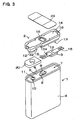
- Fig. 3 is an exploded oblique view of the embodiment of the present invention of a battery pack with a built-in protective component;
- Fig. 4 is a plane view of the embodiment of the present invention of the battery pack with a built-in protective component;
- Fig. 5 is the cross sectional view taken along line A-A of the battery pack shown in Fig 4;
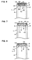
- Fig. 6 is the cross sectional view taken along line B-B of the battery pack shown in Fig 4;
- Fig. 7 is the cross sectional view taken along line C-C of the battery pack shown in Fig 4;
- Fig. 8 is the cross sectional view taken along line D-D of the battery pack shown in Fig 4.
-
- A battery pack shown in an exploded oblique view of Fig. 3 comprises a
cell 1, aterminal holder 2, a moistureabsorbent material 20 and aprotective component 3. At thecell 1, the opening of asheathing case 4 is sealed air tightly by the sealingplate 5. Furthermore, aflange 6 is provided at the circumference of the sealingplate 5 of thecell 1, being protruded to define ahollow section 7 within theflange 6. For thecell 1 in Fig. 1, theflange 6 is configured by protruding the rim of the opening of thesheathing case 4 from the sealingplate 5 as the opening edge of thesheathing case 4. This cell was manufactured by introducing the sealingplate 5 into the opening of thesheathing case 4, then laser-welding the sealingplate 5 and thesheathing case 4 such that thesheathing case 4 was air tightly sealed. - The
sheathing case 4 is manufactured by presswork of metallic sheet like aluminum, aluminum alloy or metalclad iron sheet to form a fistulous container with bottom side sealed. Thesheathing case 4 in Fig. 3 has a shape of which a cylindrical or cylindroid cylinder is pressed with particular thickness. Also, the sheathing cases may be a rectangular, cylindrical or cylindroid cylinder (not illustrated). - The sealing
plate 5 is fixed at whichterminal 8 is a center. Theterminal 8 is fixed air-tightly insulated frommetallic sealing plate 5 via insulatingpacking 9. Theterminal 8 protrudes from the surface of the sealingplate 5. Although thecell 1 shown in this Fig. has no built-in safety valve inside of theterminal 8 at the sealingplate 5, a safety valve can be provided inside of the terminal. The terminal with a built-in safety valve is provided with a perforation hole to exhaust gas trapped inside the sheathing case. The battery pack provided with a safety valve at the terminal can absorbs and eliminates an electrolyte leaked through the perforation hole by the absorbent material. - The sealing
plate 5 shown in Fig. 3 has a leakinghole 10 at a location other than theterminal 8, and ansafety valve 11 is provided on the leakinghole 10. Thesafety valve 11 is composed of a thin film which is broken by the internal pressure of the battery, the thin film being air tightly fixed at the inner face of the leakinghole 10. The thin film of thesafety valve 11 seals the leakinghole 10 air tightly when the internal pressure of the battery is lower than the predetermined pressure. If the internal pressure of the battery is higher than the predetermined pressure, the film is broken so that the gas trapped inside the battery is exhausted outside. - A
terminal holder 2 has anattachment flange 12 protruding downwardly, theattachment flange 12 being inserted into thehollow section 7 of thecell 1. Furthermore, theterminal holder 2 has astorage space 13 to hold aprotective component 3 for the battery and apreservation space 19 to hold theabsorbent material 20 at the lower face. Thisterminal holder 2 is made of an insulating material like plastic and the like, aterminal plate 14 being fixed at its upper face. It is easy to mass-produced theplastic terminal holder 2 efficiently by insertion forming of the metallicterminal plate 14. As shown in Fig. 3 and Fig. 4, theterminal plate 14 has an shape which covers upper side of theterminal holder 2 substantially other than its circumference. - The
terminal holder 2 shown in Fig. 3 provides a rib at its circumference protruding downwardly so as to form anattachment flange 12. The rib forms a ditch on the outer circumference so that theflange 6 provided on the brim of thecell 1 is inserted into the ditch. Fig. 5 and Fig. 6 show the insertion of theflange 6 of thecell 1 into the rib of theterminal holder 2. Theterminal holder 2 has thestorage space 13 to hold theprotective component 3 and thepreservation space 19 to hold theabsorbent material 20 provided inside of the rib. - The
protective component 3 mounted in thestorage space 13 has onelead 15 contacted on the top side of theterminal 8 of the sealingplate 5, and another lead 15 connected to theterminal plate 14. The body of theprotective component 3 is connected to the lower side of the lead and this body is provided in thestorage space 13. - The
protective component 3 is held between the sealingplate 5 and theterminal holder 2, and located thestorage space 13 other than theterminal 8 being, in Fig. 3, the protective-component 3 being held right of theterminal 8. The lower side of theprotective component 3 is positioned lower than the top side level of theterminal 8. In order to go through thelead 15 of theprotective component 3, which is mounted in theterminal holder 2, from the lower side of theterminal holder 2 to its upper side, thepenetration hole 16 is provided at the edge of theterminal holder 2, according to Fig. 5, the right hand edge of theterminal holder 2. - Furthermore, the
terminal holder 2 shown in Fig. 5 forms aprotrusion 17 integrally, which protrudes downwardly so as to insert into asmall hole 15A opened at thelead 15 of theprotective component 3 to hold theprotective component 3 at the right position. Theterminal holder 2 with this structure has the feature to allow the setting of theprotective component 3 at a precise position in thestorage space 13. This is because theprotrusion 17 of theterminal holder 2 is inserted into thesmall hole 15A opened thelead 15 of theprotective component 3 allowing theprotective component 3 to be set at a decided position. In addition, theprotective component 3 may be connected with theterminal holder 2 by heat welding theprotrusion 17 inserted into thesmall hole 15A. - The
terminal holder 2 shown in this Fig. defines a connectinghole 18 at the center penetrating therethrough to connect thelead 15 of theprotective component 3 to theterminal 8 of the sealingplate 5. The connectinghole 18 also go through theterminal plate 14 attached to theterminal holder 2. Thelead 15 of theprotective component 3 is deposited on theterminal 8 by introducing an electrode for spot welding rod through the connectinghole 18 and spot-welding them. - According to Fig. 5, the
terminal holder 2 shown in this Fig. has thestorage space 13 at the right side and thepreservation space 19 at the left side to hold theabsorbent material 20. Thepreservation space 19 is surrounded by the rib and with upper side enclosed by theterminal plate 14 inserted into and fixed on theterminal holder 2. At the border between thepreservation space 19 and thestorage space 13, apartition 21 is provided, being connected to the surrounding rib. Thepartition 21 divides thepreservation space 19 and thestorage space 13, and prevents the electrolyte, which has leaked and absorbed by theabsorbent material 20, from leaking outside. Thepartition 21 shown in this Fig. has a 2 row structure to secure to prevent the leaked electrolyte from theabsorbent material 20 from leaking from thepreservation space 19. As shown in Fig. 3 and 4, the rib provided theterminal holder 2 peripherally to form thepreservation space 19 defines anotch section 22 to exhaust the gas passed through thesafety valve 11 outside. - The
absorbent material 20 absorbs and maintains the electrolyte leaked from the battery. The absorbent material is made by such as a non-woven fabric aggregated by fine fibers solidly, filter paper or a minute open-cell plastic foam. Theabsorbent material 20 has a size enough to insert into thepreservation space 19, in other words, shape and size substantially same as or slightly smaller than the inner size of thepreservation space 19. Also theabsorbent material 20 opens an intake hole 20A at which it faces and corresponds to a leakinghole 10 of thesafety valve 11. - The thickness of the
absorbent material 20 is substantially same as the height of thepreservation space 19 or slightly thicker than the height of thepreservation space 19 when not being pressed, so that it can be stored slightly compressed into thepreservation space 19. Thisabsorbent material 20 fays its bottom with the sealingplate 5 so that it absorbs the electrolyte drained from thesafety valve 11 effectively. Furthermore, theabsorbent material 20 with the intake hole 20A facing the leakinghole 10 of the sealingplate 5 does not seal the opening of the leakinghole 10. For this reason, thesafety valve 11 allows smooth exhaustion of the leaking electrolyte and gas through the leakinghole 10. The gas exhausted through the leakinghole 10 is led to the intake hole 20A then, ejected through theabsorbent material 20. The electrolyte is absorbed by theabsorbent material 20 from the intake hole 20A. Alternatively, the intake hole of the absorbent material may be opened at the lower side, while sealing the upper side without penetrating therethrogh. - The
protective component 3 comprises a thermal fuse which blow out at predetermined temperature. The thermal fuse blow out to cut the current of thecell 1 off when the temperature of thecell 1 is higher than the set temperature. However the battery pack of the present invention does not limit aprotective component 3 to a thermal fuse. Instead of a thermal fuse, a PTC may be used asprotective component 3. A PTC increase electrical resistance dramatically at predetermined temperature such that the current flowing thecell 1 extremely reduced, substantially it cuts the current off. - The
protective component 3 connects thelead 15 at both ends. Thelead 15 is made by a thin metallic plate, which is connected to theterminal 8 and theterminal plate 14 by spot welding. As shown in Fig. 4, thelead 15 inserted into the throughhole 16 of theterminal holder 2 is bent along theterminal holder 2 and connected to the upper side of theterminal plate 14 by welding. - The battery pack with the above mentioned structure is manufactured by following steps.
- 1. making the
terminal holder 2 which insertsterminal plate 14 by plastic. - 2. Setting the
protective component 3 into thestorage space 13 of theterminal holder 2, and connecting thelead 15 of theprotective component 3 to theterminal plate 14. It may be made by inserting theprotrusion 17 provided on theterminal holder 2 into thesmall hole 15A opened at thelead 15 of theprotective component 3, then squash theprotrusion 17 to temporarily hold theprotective component 3 to theterminal holder 2. - 3. Setting the
absorbent material 20 into thepreservation space 19 of theterminal holder 2. Theabsorbent material 20 is inserted into thepreservation space 19 and maintained at a predetermined position. The absorbent material may be glued at the inner face of the terminal holder. - 4. Inserting the
attachment flange 12 of theterminal holder 2 into thehollow section 7 of thecell 1 to attach theterminal holder 2 with thecell 1 at the predetermined position. Here, applying some adhesive at the lower side of theprotective component 3 and adhere it on the surface of the sealingplate 5. Further, it may be possible to apply adhesive to the bottom side of the absorbent material and adhere it to the surface of the sealing plate. - 5. Inserting the electrode rod into the
connection hole 18 of theterminal holder 2 while theterminal holder 2 is attached to thecell 1 at the predetermined position, and welding thelead 15 of theprotective component 3 to theterminal 8. - 6. As shown in Fig. 3 and 4, adhering a
film 23 to theterminal holder 2 and thesheathing case 4 of thecell 1 such that theterminal holder 2 is connected to thecell 1. In the battery shown in Fig., theterminal holder 2 is fixed to thesheathing case 4 by mean of an adhesive film. However the terminal holder and the cell may be connected by film like a heat-shrinkable film. -
- Then, welding the lead plate being pulled out the
sheathing case 4 and theterminal plate 14, inserting into the case, maybe covering with a heat-shrinkable film thereby the battery pack is obtained. - As this invention may be embodied in several forms without departing from the spirit of essential characteristics thereof, the present embodiment is therefore illustrative and not restrictive, since the scope of the invention is defined by the appended claims rather than by the description preceding them, and all changes that fall within meets and bounds of the claims, or equivalence of such meets and bounds thereof are therefore intended to be embraced by the claims.
Claims (21)
- A battery pack comprising:a sheathing case;a cell covering an opening of the sheathing case with a sealing plate air tightly, the sealing plate having a terminal protruding from its surface;a protective component for the battery;a terminal holder which is set at the position covering the sealing plate of the cell and has a storage space to store a protective component inside between the sealing plate and the terminal holder, and is made itself of an insulating material; andwherein the protective component for the battery is located within the storage space provided between the terminal holder and the sealing plate and at area bther than the terminal being, with the lower side of the protective component being lower than the top side level of the terminal.
- A battery pack as recited in claim 1 wherein the cell has a flange protruding on the rim of the sealing plate, the terminal holder has an attachment flange to be inserted into the inner side of the flange, and the attachment flange is inserted into a hollow section of the cell so as to form a storage space between the terminal holder and the sealing plate.
- A battery pack as recited in claim 1 wherein the protective component has leads, the lead being connected to top side of the terminal, the body of the protective component being connected to the lower side of the lead and mounted in the storage space.
- A battery pack as recited in claim 1 wherein the protective component is mounted in the storage space, being between the sealing plate and the terminal holder.
- A battery pack as recited in claim 4 wherein the protective component is adhered on the surface of the sealing plate.
- A battery pack as recited in claim 3 wherein one of the lead of the protective component is connected to the terminal provided on the sealing plate and another lead penetrates through the terminal holder and is connected to the terminal plate attached on the upper side of the terminal holder.
- A battery pack as recited in claim 1 wherein the protective component defines a small hole on the lead, and the terminal holder has a flange provided thereon protruding downwardly whereby the flange is inserted into the small hole to maintain the protective component at a predetermined location in the terminal holder.
- A battery pack as recited in claim 7 wherein the flange is squashed such that the protective component is connected to the terminal holder.
- A battery pack as recited in claim 1 wherein the terminal holder defines a connection hole penetrating therethrough at the center thereof to connect the lead of the protective component with the terminal of the sealing plate.
- A battery pack as recited in claim 1 wherein the rim around the opening of the sheathing case protrudes apart from the sealing plate so as to form a flange itself.
- A battery pack as recited in claim 1 wherein the terminal holder is connected to the sheathing case via a film.
- A battery pack as recited in claim 1 wherein the sheathing case of the cell is either rectangular barrel, cylindrical barrel, cylindroid barrel, or tubular barrel of shape like pressed cylindrical or cylindroid barrel at predetermined thickness.
- A battery pack as recited in claim 1 wherein the terminal holder is made by plastic, into which the terminal plate made by a metal sheet is inserted and fixed to form thereof.
- A battery pack as recited in claim 1 wherein a preservation space is provided between the sealing plate and the terminal holder other than the area of the terminal being, and a absorbent material which absorbs the electrolyte leaked from the sealing plate is stored therein.
- A battery pack as recited in claim 14 wherein the cell defines a leaking hole on the sealing plate opening apart from the terminal, and has a safety valve which is made by a thin film which breaks by the internal pressure of battery.
- A battery pack as recited in claim 14 wherein the terminal holder has a partition to form and divide a storage space to store the protective component and the preservation space to store the absorbent material.
- A battery pack as recited in claim 14 wherein the preservation space is surrounded by a rib and sealed upper side thereof with terminal plate attached on the upper side of terminal holder.
- A battery pack as recited in claim 17 wherein the rib provided around the terminal holder to form the preservation space have a notch section to exhaust the gas passing through the safety valve of the cell.
- A battery pack as recited in claim 14 wherein the absorbent material is made by either a non-woven fabric aggregated by fine fibers solidly, filter paper or a minute open-cell plastic foam.
- A battery pack as recited in claim 14 wherein the absorbent material has a shape and size substantially same as or slightly smaller than the inner size of the preservation space, and opens an intake hole at which it corresponds to a leaking hole of the safety valve.
- A battery pack as recited in claim 14 wherein the absorbent material is adhered of the bottom side to the sealing plate.
Applications Claiming Priority (4)
| Application Number | Priority Date | Filing Date | Title |
|---|---|---|---|
| JP04463199A JP3454738B2 (en) | 1999-02-23 | 1999-02-23 | Battery pack with built-in protection element |
| JP4463199 | 1999-02-23 | ||
| JP4579099 | 1999-02-24 | ||
| JP04579099A JP3475113B2 (en) | 1999-02-24 | 1999-02-24 | Battery pack |
Publications (2)
| Publication Number | Publication Date |
|---|---|
| EP1032060A1 true EP1032060A1 (en) | 2000-08-30 |
| EP1032060B1 EP1032060B1 (en) | 2006-08-30 |
Family
ID=26384581
Family Applications (1)
| Application Number | Title | Priority Date | Filing Date |
|---|---|---|---|
| EP00103535A Expired - Lifetime EP1032060B1 (en) | 1999-02-23 | 2000-02-18 | Battery pack |
Country Status (6)
| Country | Link |
|---|---|
| US (1) | US6432575B1 (en) |
| EP (1) | EP1032060B1 (en) |
| KR (1) | KR100583223B1 (en) |
| CN (1) | CN1163988C (en) |
| DE (1) | DE60030345T2 (en) |
| TW (1) | TW432736B (en) |
Cited By (5)
| Publication number | Priority date | Publication date | Assignee | Title |
|---|---|---|---|---|
| WO2002035558A3 (en) * | 2000-10-25 | 2003-07-10 | Tyco Electronics Corp | Circuit protection device |
| US6899972B2 (en) * | 2001-10-18 | 2005-05-31 | Samsung Sdi Co., Ltd. | Secondary battery with thermal protector |
| EP1780819A1 (en) * | 2005-10-31 | 2007-05-02 | Black & Decker, Inc. | Cell connection straps for battery cells of a battery pack |
| EP1422771A4 (en) * | 2001-08-07 | 2009-01-21 | Panasonic Corp | SECONDARY BATTERY WITH WATER-FREE ELECTROLYTE |
| EP1804318A3 (en) * | 2005-12-29 | 2010-06-09 | Samsung SDI Co., Ltd. | Rechargeable battery |
Families Citing this family (55)
| Publication number | Priority date | Publication date | Assignee | Title |
|---|---|---|---|---|
| KR100484420B1 (en) * | 1999-03-30 | 2005-04-22 | 마츠시타 덴끼 산교 가부시키가이샤 | Rechargeable battery with protective circuit |
| JP4904614B2 (en) * | 2000-06-22 | 2012-03-28 | パナソニック株式会社 | Battery pack and manufacturing method thereof |
| JP4039657B2 (en) * | 2001-10-16 | 2008-01-30 | Necトーキン株式会社 | Battery pack |
| JP4494713B2 (en) | 2001-12-04 | 2010-06-30 | パナソニック株式会社 | Battery pack |
| US6824917B2 (en) * | 2001-12-11 | 2004-11-30 | Nokia Corporation | Battery system for a portable electronic device |
| JP4629952B2 (en) * | 2002-02-13 | 2011-02-09 | パナソニック株式会社 | Manufacturing method of secondary battery |
| JP4440548B2 (en) | 2002-02-13 | 2010-03-24 | パナソニック株式会社 | Battery and manufacturing method thereof |
| CN1630954B (en) | 2002-02-13 | 2012-02-29 | 松下电器产业株式会社 | Battery pack manufacturing method |
| JP4589596B2 (en) * | 2002-03-22 | 2010-12-01 | パナソニック株式会社 | Battery pack |
| KR100974996B1 (en) | 2002-10-31 | 2010-08-09 | 산요덴키가부시키가이샤 | Pack battery |
| CN2631052Y (en) * | 2003-06-13 | 2004-08-04 | 比亚迪股份有限公司 | Lithium ion cell |
| JP4130160B2 (en) * | 2003-09-16 | 2008-08-06 | 三洋電機株式会社 | Pack battery |
| JP3873966B2 (en) * | 2003-10-24 | 2007-01-31 | ソニー株式会社 | battery pack |
| EP1692734B1 (en) * | 2003-12-08 | 2015-03-18 | LG Chem, Ltd. | Pcm mold and battery having the same |
| WO2005074055A1 (en) * | 2004-01-28 | 2005-08-11 | Lg Chem, Ltd. | Secondary battery of assemble-type structure |
| KR100682731B1 (en) * | 2004-02-13 | 2007-02-15 | 주식회사 엘지화학 | Improved battery pack |
| JP5068544B2 (en) * | 2004-02-18 | 2012-11-07 | エルジー・ケム・リミテッド | Integrated type cap assembly including a protection circuit board and a secondary battery including the same |
| KR100585760B1 (en) * | 2004-02-28 | 2006-06-07 | 엘지전자 주식회사 | Molding part reinforcement of battery |
| KR100537538B1 (en) * | 2004-03-30 | 2005-12-16 | 삼성에스디아이 주식회사 | Prismatic type secondary battery having lead plate |
| EP1805828B1 (en) * | 2004-07-26 | 2012-05-09 | LG Chem, Ltd. | Connecting structure for electrical connection of pcm and battery cell and secondary battery pack containing the same |
| WO2006046343A1 (en) | 2004-10-27 | 2006-05-04 | Matsushita Electric Industrial Co., Ltd. | Battery pack |
| KR20060042819A (en) * | 2004-11-10 | 2006-05-15 | 엘지전자 주식회사 | Resin fastening device with battery protection circuit |
| KR100877816B1 (en) * | 2005-01-21 | 2009-01-12 | 주식회사 엘지화학 | Battery pack with improved safety |
| KR100930476B1 (en) * | 2005-01-25 | 2009-12-09 | 주식회사 엘지화학 | Cap assembly molded body and secondary battery comprising the same |
| KR100696782B1 (en) * | 2005-04-27 | 2007-03-19 | 삼성에스디아이 주식회사 | Lithium-ion Secondary Battery |
| JP4604912B2 (en) * | 2005-08-12 | 2011-01-05 | ソニー株式会社 | Secondary battery |
| US7964300B2 (en) * | 2005-09-30 | 2011-06-21 | Tdk-Lambda Corporation | Battery pack |
| KR100585380B1 (en) * | 2005-12-16 | 2006-05-30 | 주식회사 이랜텍 | Battery pack |
| JP5111760B2 (en) * | 2005-12-21 | 2013-01-09 | 三星エスディアイ株式会社 | Battery protection element and battery |
| KR100824873B1 (en) * | 2006-02-28 | 2008-04-23 | 삼성에스디아이 주식회사 | Lithium-ion Secondary Battery |
| KR100886571B1 (en) | 2006-08-07 | 2009-03-05 | 주식회사 엘지화학 | Battery pack case |
| JP5084205B2 (en) * | 2006-08-11 | 2012-11-28 | 三洋電機株式会社 | Nonaqueous electrolyte secondary battery |
| US20110008655A1 (en) * | 2006-10-20 | 2011-01-13 | White Daniel J | Cell connection straps for battery cells of a battery pack |
| KR100846956B1 (en) | 2006-11-21 | 2008-07-17 | 삼성에스디아이 주식회사 | Secondary Battery with Protection Circuit Module |
| JP2008166191A (en) * | 2006-12-28 | 2008-07-17 | Sanyo Electric Co Ltd | Battery pack |
| KR100917751B1 (en) * | 2007-09-20 | 2009-09-15 | 삼성에스디아이 주식회사 | Pack type secondary battery |
| KR100867923B1 (en) * | 2007-10-30 | 2008-11-10 | 삼성에스디아이 주식회사 | Secondary Battery with Protective Circuit Board |
| KR101372477B1 (en) * | 2008-03-06 | 2014-03-11 | 삼성에스디아이 주식회사 | Cap assembly and secondary battery using the same |
| CN101789498A (en) * | 2009-01-23 | 2010-07-28 | 松下能源(无锡)有限公司 | Insulating cap of battery, battery with insulating cap and battery pack thereof |
| KR101084783B1 (en) * | 2009-09-01 | 2011-11-22 | 삼성에스디아이 주식회사 | Secondary Battery and Manufacturing Method Thereof |
| KR101066001B1 (en) * | 2009-09-01 | 2011-09-19 | 삼성에스디아이 주식회사 | Secondary battery |
| US20110091749A1 (en) * | 2009-10-15 | 2011-04-21 | Ac Propulsion, Inc. | Battery Pack |
| DE102009050878A1 (en) * | 2009-10-27 | 2011-04-28 | Carl Freudenberg Kg | Battery with a filter element arranged outside of the battery housing |
| EP3896783A1 (en) | 2010-02-17 | 2021-10-20 | Kabushiki Kaisha Toshiba | Battery comprising a lid, a safety valve and a current collecting lead |
| AT509573B1 (en) * | 2010-02-25 | 2012-01-15 | Norman Neuhold | accumulator |
| DE102010027974A1 (en) * | 2010-04-20 | 2011-10-20 | Robert Bosch Gmbh | Hand power tools battery |
| KR101166024B1 (en) * | 2010-08-04 | 2012-07-19 | 삼성에스디아이 주식회사 | External terminal assembly and battery pack using the same |
| TWI431837B (en) | 2011-06-27 | 2014-03-21 | Delta Electronics Inc | Energy storage device package |
| US8691410B2 (en) * | 2011-11-02 | 2014-04-08 | Samsung Sdi Co., Ltd. | Battery pack |
| CN103635044B (en) * | 2012-08-20 | 2017-02-08 | 珠海格力电器股份有限公司 | Remote controller |
| EP2731164B1 (en) * | 2012-11-12 | 2017-06-28 | Samsung SDI Co., Ltd. | Battery system |
| KR101711993B1 (en) * | 2013-09-10 | 2017-03-03 | 삼성에스디아이 주식회사 | Rechargeable battery having fuse |
| US9385356B2 (en) | 2014-04-30 | 2016-07-05 | Ford Global Technologies, Llc. | Terminal holder for electric vehicle battery assembly |
| USD837790S1 (en) * | 2016-08-03 | 2019-01-08 | Transcend Information, Inc. | Mobile storage device |
| US11130196B2 (en) * | 2017-03-30 | 2021-09-28 | Nio Usa, Inc. | Single-position sequential laser welding system |
Citations (8)
| Publication number | Priority date | Publication date | Assignee | Title |
|---|---|---|---|---|
| US4035552A (en) * | 1976-07-23 | 1977-07-12 | Gte Laboratories Incorporated | Electrochemical cell |
| EP0228983A2 (en) * | 1985-12-02 | 1987-07-15 | Emerson Electric Co. | Hermetically sealed battery cover assembly |
| US4788112A (en) * | 1987-08-17 | 1988-11-29 | Kung Chin Chung | Rechargeable storage battery |
| EP0674351A2 (en) * | 1994-03-03 | 1995-09-27 | Japan Storage Battery Company Limited | Battery and safety device therefor |
| FR2743452A1 (en) * | 1996-01-08 | 1997-07-11 | Accumulateurs Fixes | Safety device for electrochemical generator |
| US5705290A (en) * | 1995-08-11 | 1998-01-06 | Alps Electric Co., Ltd. | Secondary cell safety device including pressure release mechanism and current cutoff mechanism |
| EP0844622A1 (en) * | 1995-08-07 | 1998-05-27 | K.K. Raychem | Ptc device and battery pack using the same |
| JPH11154504A (en) * | 1997-11-20 | 1999-06-08 | Alps Electric Co Ltd | Pressure cutoff sensor |
Family Cites Families (5)
| Publication number | Priority date | Publication date | Assignee | Title |
|---|---|---|---|---|
| JPH07263028A (en) * | 1994-03-25 | 1995-10-13 | Fuji Photo Film Co Ltd | Non-aqueous secondary battery |
| JP2979963B2 (en) | 1994-07-21 | 1999-11-22 | 日本電池株式会社 | Rechargeable battery |
| JP3573919B2 (en) * | 1997-07-01 | 2004-10-06 | 三洋電機株式会社 | Battery pack with temperature sensor |
| JP4000646B2 (en) * | 1997-12-17 | 2007-10-31 | 宇部興産株式会社 | Non-aqueous electrolyte for secondary batteries |
| US5993990A (en) * | 1998-05-15 | 1999-11-30 | Moltech Corporation | PTC current limiting header assembly |
-
1999
- 1999-12-30 TW TW088123282A patent/TW432736B/en not_active IP Right Cessation
-
2000
- 2000-01-25 KR KR1020000003458A patent/KR100583223B1/en not_active Expired - Fee Related
- 2000-02-09 CN CNB001023020A patent/CN1163988C/en not_active Expired - Fee Related
- 2000-02-18 DE DE60030345T patent/DE60030345T2/en not_active Expired - Lifetime
- 2000-02-18 EP EP00103535A patent/EP1032060B1/en not_active Expired - Lifetime
- 2000-02-22 US US09/510,310 patent/US6432575B1/en not_active Expired - Fee Related
Patent Citations (8)
| Publication number | Priority date | Publication date | Assignee | Title |
|---|---|---|---|---|
| US4035552A (en) * | 1976-07-23 | 1977-07-12 | Gte Laboratories Incorporated | Electrochemical cell |
| EP0228983A2 (en) * | 1985-12-02 | 1987-07-15 | Emerson Electric Co. | Hermetically sealed battery cover assembly |
| US4788112A (en) * | 1987-08-17 | 1988-11-29 | Kung Chin Chung | Rechargeable storage battery |
| EP0674351A2 (en) * | 1994-03-03 | 1995-09-27 | Japan Storage Battery Company Limited | Battery and safety device therefor |
| EP0844622A1 (en) * | 1995-08-07 | 1998-05-27 | K.K. Raychem | Ptc device and battery pack using the same |
| US5705290A (en) * | 1995-08-11 | 1998-01-06 | Alps Electric Co., Ltd. | Secondary cell safety device including pressure release mechanism and current cutoff mechanism |
| FR2743452A1 (en) * | 1996-01-08 | 1997-07-11 | Accumulateurs Fixes | Safety device for electrochemical generator |
| JPH11154504A (en) * | 1997-11-20 | 1999-06-08 | Alps Electric Co Ltd | Pressure cutoff sensor |
Non-Patent Citations (1)
| Title |
|---|
| PATENT ABSTRACTS OF JAPAN vol. 1999, no. 11 30 September 1999 (1999-09-30) * |
Cited By (5)
| Publication number | Priority date | Publication date | Assignee | Title |
|---|---|---|---|---|
| WO2002035558A3 (en) * | 2000-10-25 | 2003-07-10 | Tyco Electronics Corp | Circuit protection device |
| EP1422771A4 (en) * | 2001-08-07 | 2009-01-21 | Panasonic Corp | SECONDARY BATTERY WITH WATER-FREE ELECTROLYTE |
| US6899972B2 (en) * | 2001-10-18 | 2005-05-31 | Samsung Sdi Co., Ltd. | Secondary battery with thermal protector |
| EP1780819A1 (en) * | 2005-10-31 | 2007-05-02 | Black & Decker, Inc. | Cell connection straps for battery cells of a battery pack |
| EP1804318A3 (en) * | 2005-12-29 | 2010-06-09 | Samsung SDI Co., Ltd. | Rechargeable battery |
Also Published As
| Publication number | Publication date |
|---|---|
| US6432575B1 (en) | 2002-08-13 |
| CN1163988C (en) | 2004-08-25 |
| DE60030345D1 (en) | 2006-10-12 |
| KR20000062499A (en) | 2000-10-25 |
| DE60030345T2 (en) | 2007-08-30 |
| CN1264925A (en) | 2000-08-30 |
| EP1032060B1 (en) | 2006-08-30 |
| HK1028490A1 (en) | 2001-02-16 |
| KR100583223B1 (en) | 2006-05-24 |
| TW432736B (en) | 2001-05-01 |
Similar Documents
| Publication | Publication Date | Title |
|---|---|---|
| EP1032060B1 (en) | Battery pack | |
| EP1826839B1 (en) | Secondary battery | |
| EP1919009B1 (en) | Lithium Rechargeable Battery | |
| KR100551887B1 (en) | Secondary battery | |
| CN1321468C (en) | Quadrangular secondary battery having lead plate attached thereto | |
| CN101174706B (en) | Secondary battery and method of fabricating the same | |
| US20040251872A1 (en) | Lithium ion batteries | |
| EP1039565A2 (en) | A sealed battery with less electrolyte leakage | |
| JP3454738B2 (en) | Battery pack with built-in protection element | |
| CN101312256B (en) | Lithium polymer battery | |
| KR100696782B1 (en) | Lithium-ion Secondary Battery | |
| JP3475113B2 (en) | Battery pack | |
| KR20040054232A (en) | Secondary battery | |
| KR20040107868A (en) | Pouched-type lithium secondary battery | |
| JP2001332226A (en) | Alkaline batteries | |
| KR100561293B1 (en) | Secondary battery | |
| KR101122904B1 (en) | Battery pack | |
| KR100573103B1 (en) | Cap assembly of secondary battery | |
| KR100580768B1 (en) | Resin Molded Secondary Battery | |
| KR100571233B1 (en) | Secondary battery | |
| KR100686853B1 (en) | Can type secondary battery | |
| JPS6344947Y2 (en) | ||
| HK1028490B (en) | A pack battery |
Legal Events
| Date | Code | Title | Description |
|---|---|---|---|
| PUAI | Public reference made under article 153(3) epc to a published international application that has entered the european phase |
Free format text: ORIGINAL CODE: 0009012 |
|
| AK | Designated contracting states |
Kind code of ref document: A1 Designated state(s): DE FR GB IT |
|
| AX | Request for extension of the european patent |
Free format text: AL;LT;LV;MK;RO;SI |
|
| 17P | Request for examination filed |
Effective date: 20000907 |
|
| AKX | Designation fees paid |
Free format text: DE FR GB IT |
|
| 17Q | First examination report despatched |
Effective date: 20040218 |
|
| GRAP | Despatch of communication of intention to grant a patent |
Free format text: ORIGINAL CODE: EPIDOSNIGR1 |
|
| GRAS | Grant fee paid |
Free format text: ORIGINAL CODE: EPIDOSNIGR3 |
|
| GRAA | (expected) grant |
Free format text: ORIGINAL CODE: 0009210 |
|
| AK | Designated contracting states |
Kind code of ref document: B1 Designated state(s): DE FR GB IT |
|
| PG25 | Lapsed in a contracting state [announced via postgrant information from national office to epo] |
Ref country code: IT Free format text: LAPSE BECAUSE OF FAILURE TO SUBMIT A TRANSLATION OF THE DESCRIPTION OR TO PAY THE FEE WITHIN THE PRESCRIBED TIME-LIMIT;WARNING: LAPSES OF ITALIAN PATENTS WITH EFFECTIVE DATE BEFORE 2007 MAY HAVE OCCURRED AT ANY TIME BEFORE 2007. THE CORRECT EFFECTIVE DATE MAY BE DIFFERENT FROM THE ONE RECORDED. Effective date: 20060830 |
|
| REG | Reference to a national code |
Ref country code: GB Ref legal event code: FG4D |
|
| REF | Corresponds to: |
Ref document number: 60030345 Country of ref document: DE Date of ref document: 20061012 Kind code of ref document: P |
|
| ET | Fr: translation filed | ||
| PLBE | No opposition filed within time limit |
Free format text: ORIGINAL CODE: 0009261 |
|
| STAA | Information on the status of an ep patent application or granted ep patent |
Free format text: STATUS: NO OPPOSITION FILED WITHIN TIME LIMIT |
|
| 26N | No opposition filed |
Effective date: 20070531 |
|
| PGFP | Annual fee paid to national office [announced via postgrant information from national office to epo] |
Ref country code: IT Payment date: 20120222 Year of fee payment: 13 |
|
| REG | Reference to a national code |
Ref country code: DE Ref legal event code: R082 Ref document number: 60030345 Country of ref document: DE Representative=s name: SCHUMACHER & WILLSAU PATENTANWALTSGESELLSCHAFT, DE |
|
| PGFP | Annual fee paid to national office [announced via postgrant information from national office to epo] |
Ref country code: GB Payment date: 20130213 Year of fee payment: 14 Ref country code: DE Payment date: 20130213 Year of fee payment: 14 Ref country code: FR Payment date: 20130301 Year of fee payment: 14 |
|
| REG | Reference to a national code |
Ref country code: DE Ref legal event code: R119 Ref document number: 60030345 Country of ref document: DE |
|
| GBPC | Gb: european patent ceased through non-payment of renewal fee |
Effective date: 20140218 |
|
| REG | Reference to a national code |
Ref country code: FR Ref legal event code: ST Effective date: 20141031 |
|
| REG | Reference to a national code |
Ref country code: DE Ref legal event code: R119 Ref document number: 60030345 Country of ref document: DE Effective date: 20140902 |
|
| PG25 | Lapsed in a contracting state [announced via postgrant information from national office to epo] |
Ref country code: GB Free format text: LAPSE BECAUSE OF NON-PAYMENT OF DUE FEES Effective date: 20140218 Ref country code: FR Free format text: LAPSE BECAUSE OF NON-PAYMENT OF DUE FEES Effective date: 20140228 Ref country code: DE Free format text: LAPSE BECAUSE OF NON-PAYMENT OF DUE FEES Effective date: 20140902 |
|
| PG25 | Lapsed in a contracting state [announced via postgrant information from national office to epo] |
Ref country code: IT Free format text: LAPSE BECAUSE OF NON-PAYMENT OF DUE FEES Effective date: 20140218 |