EP1031970A2 - Optical disk medium having features for radial tilt detection and apparatus for measuring radial tilt - Google Patents
Optical disk medium having features for radial tilt detection and apparatus for measuring radial tilt Download PDFInfo
- Publication number
- EP1031970A2 EP1031970A2 EP00301412A EP00301412A EP1031970A2 EP 1031970 A2 EP1031970 A2 EP 1031970A2 EP 00301412 A EP00301412 A EP 00301412A EP 00301412 A EP00301412 A EP 00301412A EP 1031970 A2 EP1031970 A2 EP 1031970A2
- Authority
- EP
- European Patent Office
- Prior art keywords
- groove
- height
- land
- disk
- radial tilt
- Prior art date
- Legal status (The legal status is an assumption and is not a legal conclusion. Google has not performed a legal analysis and makes no representation as to the accuracy of the status listed.)
- Granted
Links
- 230000003287 optical effect Effects 0.000 title claims abstract description 65
- 238000001514 detection method Methods 0.000 title description 10
- 238000005259 measurement Methods 0.000 claims abstract description 34
- 230000008859 change Effects 0.000 claims description 9
- 238000000034 method Methods 0.000 claims description 3
- 230000000694 effects Effects 0.000 abstract description 12
- 239000000758 substrate Substances 0.000 abstract description 11
- 239000010409 thin film Substances 0.000 description 8
- 206010010071 Coma Diseases 0.000 description 7
- 230000004048 modification Effects 0.000 description 3
- 238000012986 modification Methods 0.000 description 3
- 230000004044 response Effects 0.000 description 3
- 238000013459 approach Methods 0.000 description 2
- 238000013461 design Methods 0.000 description 2
- 238000001914 filtration Methods 0.000 description 2
- 238000012545 processing Methods 0.000 description 2
- 230000035945 sensitivity Effects 0.000 description 2
- 230000004075 alteration Effects 0.000 description 1
- 230000001427 coherent effect Effects 0.000 description 1
- 238000010586 diagram Methods 0.000 description 1
- 230000002452 interceptive effect Effects 0.000 description 1
- 230000007246 mechanism Effects 0.000 description 1
- 239000011241 protective layer Substances 0.000 description 1
- 230000001360 synchronised effect Effects 0.000 description 1
- 230000007704 transition Effects 0.000 description 1
Images




Classifications
-
- G—PHYSICS
- G11—INFORMATION STORAGE
- G11B—INFORMATION STORAGE BASED ON RELATIVE MOVEMENT BETWEEN RECORD CARRIER AND TRANSDUCER
- G11B7/00—Recording or reproducing by optical means, e.g. recording using a thermal beam of optical radiation by modifying optical properties or the physical structure, reproducing using an optical beam at lower power by sensing optical properties; Record carriers therefor
-
- G—PHYSICS
- G11—INFORMATION STORAGE
- G11B—INFORMATION STORAGE BASED ON RELATIVE MOVEMENT BETWEEN RECORD CARRIER AND TRANSDUCER
- G11B7/00—Recording or reproducing by optical means, e.g. recording using a thermal beam of optical radiation by modifying optical properties or the physical structure, reproducing using an optical beam at lower power by sensing optical properties; Record carriers therefor
- G11B7/24—Record carriers characterised by shape, structure or physical properties, or by the selection of the material
- G11B7/2407—Tracks or pits; Shape, structure or physical properties thereof
- G11B7/24085—Pits
-
- G—PHYSICS
- G11—INFORMATION STORAGE
- G11B—INFORMATION STORAGE BASED ON RELATIVE MOVEMENT BETWEEN RECORD CARRIER AND TRANSDUCER
- G11B7/00—Recording or reproducing by optical means, e.g. recording using a thermal beam of optical radiation by modifying optical properties or the physical structure, reproducing using an optical beam at lower power by sensing optical properties; Record carriers therefor
- G11B7/007—Arrangement of the information on the record carrier, e.g. form of tracks, actual track shape, e.g. wobbled, or cross-section, e.g. v-shaped; Sequential information structures, e.g. sectoring or header formats within a track
- G11B7/00745—Sectoring or header formats within a track
-
- G—PHYSICS
- G11—INFORMATION STORAGE
- G11B—INFORMATION STORAGE BASED ON RELATIVE MOVEMENT BETWEEN RECORD CARRIER AND TRANSDUCER
- G11B7/00—Recording or reproducing by optical means, e.g. recording using a thermal beam of optical radiation by modifying optical properties or the physical structure, reproducing using an optical beam at lower power by sensing optical properties; Record carriers therefor
- G11B7/08—Disposition or mounting of heads or light sources relatively to record carriers
- G11B7/09—Disposition or mounting of heads or light sources relatively to record carriers with provision for moving the light beam or focus plane for the purpose of maintaining alignment of the light beam relative to the record carrier during transducing operation, e.g. to compensate for surface irregularities of the latter or for track following
- G11B7/095—Disposition or mounting of heads or light sources relatively to record carriers with provision for moving the light beam or focus plane for the purpose of maintaining alignment of the light beam relative to the record carrier during transducing operation, e.g. to compensate for surface irregularities of the latter or for track following specially adapted for discs, e.g. for compensation of eccentricity or wobble
- G11B7/0956—Disposition or mounting of heads or light sources relatively to record carriers with provision for moving the light beam or focus plane for the purpose of maintaining alignment of the light beam relative to the record carrier during transducing operation, e.g. to compensate for surface irregularities of the latter or for track following specially adapted for discs, e.g. for compensation of eccentricity or wobble to compensate for tilt, skew, warp or inclination of the disc, i.e. maintain the optical axis at right angles to the disc
-
- G—PHYSICS
- G11—INFORMATION STORAGE
- G11B—INFORMATION STORAGE BASED ON RELATIVE MOVEMENT BETWEEN RECORD CARRIER AND TRANSDUCER
- G11B7/00—Recording or reproducing by optical means, e.g. recording using a thermal beam of optical radiation by modifying optical properties or the physical structure, reproducing using an optical beam at lower power by sensing optical properties; Record carriers therefor
- G11B7/08—Disposition or mounting of heads or light sources relatively to record carriers
- G11B7/09—Disposition or mounting of heads or light sources relatively to record carriers with provision for moving the light beam or focus plane for the purpose of maintaining alignment of the light beam relative to the record carrier during transducing operation, e.g. to compensate for surface irregularities of the latter or for track following
- G11B7/0901—Disposition or mounting of heads or light sources relatively to record carriers with provision for moving the light beam or focus plane for the purpose of maintaining alignment of the light beam relative to the record carrier during transducing operation, e.g. to compensate for surface irregularities of the latter or for track following for track following only
-
- G—PHYSICS
- G11—INFORMATION STORAGE
- G11B—INFORMATION STORAGE BASED ON RELATIVE MOVEMENT BETWEEN RECORD CARRIER AND TRANSDUCER
- G11B7/00—Recording or reproducing by optical means, e.g. recording using a thermal beam of optical radiation by modifying optical properties or the physical structure, reproducing using an optical beam at lower power by sensing optical properties; Record carriers therefor
- G11B7/08—Disposition or mounting of heads or light sources relatively to record carriers
- G11B7/09—Disposition or mounting of heads or light sources relatively to record carriers with provision for moving the light beam or focus plane for the purpose of maintaining alignment of the light beam relative to the record carrier during transducing operation, e.g. to compensate for surface irregularities of the latter or for track following
- G11B7/0938—Disposition or mounting of heads or light sources relatively to record carriers with provision for moving the light beam or focus plane for the purpose of maintaining alignment of the light beam relative to the record carrier during transducing operation, e.g. to compensate for surface irregularities of the latter or for track following servo format, e.g. guide tracks, pilot signals
Definitions
- This invention relates generally to optical disks and more specifically to an optical disk that includes physical features suitable for use in detecting radial tilt of the disk relative to an ideal plane.
- Optical disks for example, compact disks (CD), require precise focusing of an optical beam onto a data surface.
- One or more light beams (typically from a laser diode), illuminate one or more spots on the disk, and are reflected back into an optical head.
- the reflected light beams generally may also carry information about tracking error (how well a beam is centered on a data track), and focus error (how well a beam is focused onto the data surface).
- the data surface of an optical disk is protected by a transparent substrate on the side that is illuminated by the laser. In general, whenever an illuminating beam must pass through the substrate to reach the data surface, disk tilt degrades the focus quality of the illuminating beam.
- tilt detection and compensation are not required for the data densities involved in CD media.
- radial tilt detection and compensation may be necessary for higher data densities, for example, for Digital Versatile Disks (DVD). Note that tilt may have a radial component and a tangential component, but the radial component is typically much larger (and therefore of more concern) than the tangential component.
- Some optical disk drives use a separate light beam for radial tilt measurement. See, for example, U.S. Patent Numbers 5,657,303 and 5,699,340.
- ASMO Advanced Storage Magneto Optic
- ASMO media is preformatted with permanent (embossed) headers. Each header starts with tilt measurement marks, formed into the walls of a groove defining a track. The tilt measurement information does not interfere with the data because data and headers do not coexist at the same place on the disk.
- An optical disc medium in accordance with the invention has a recording thin film structure (data surface) with grooves and lands behind a transparent substrate.
- radial tilt measurement features are provided in the data surface, wherein the height of the grooves and lands are changed, preferably over a short circumferential length.
- the height of a groove may be raised to the height of a land and the height of a land (over a short length) may be reduced to the height of a groove.
- the optical disk medium is designed in conjunction with the optical system of the drive so that when the focused laser spot is centered on a groove, a tracking error signal (for example, radial push-pull signal) is zero even if the disk is radially tilted.
- a tracking error signal for example, radial push-pull signal
- the tracking error signal varies when the disk is radially tilted.
- an abrupt step in the tracking error signal provides a measure of the magnitude and direction of radial tilt.
- the abrupt steps are removed from the tracking error signal by existing low-pass filtering.
- the tilt measurement features have negligible effect on the data signal, and negligible effect on filtered tracking error and focus error signals. No changes are required for the drive optical system. The only drive change required is additional signal processing of the tracking error signal to detect abrupt steps.
- Some proposed formats use a format called single-spiral groove and land recording, in which each spiral groove completes one revolution of the disk and then ends at the beginning of a spiral land. Each spiral land completes one revolution of the disk and then ends at the beginning of a spiral groove. Data is recorded on the grooves and on the lands.
- the method of using a change in the groove height to measure radial tilt is also applicable to single-spiral groove and land recording.
- Figure 1A illustrates an optical disk system.
- the system in figure 1A depicts representative components in a manner suitable to illustrate the invention within the context of a drive, but the system of figure 1A may not accurately depict any actual optical disk system, and there are many variations and many different configurations.
- a laser diode 100 emits coherent but uncollimated light. The light passes through a collimation lens 102, is reflected from a partially-reflecting mirror 104, passes through an aperture 106, through a focusing lens 108, and is focused onto a data surface within an optical disk 110. Light reflected from the data surface in the disk 110 passes through partially-reflecting mirror 104, through a focusing lens 112, and is detected by a detector array 114.
- optical head (reference 116).
- An electronic signal processing system 117 receives signals from the detector array 114 and derives various signals, such as a data signal, a tracking error signal, and a focus error signal.
- dashed line 118 represents the optical axis or centerline of the optical system.
- angle ⁇ is the angle between the optical axis and the plane of the illuminated area of the disk.
- the plane of the area on the disk 110 that is illuminated by the focused laser spot is orthogonal to the optical axis 118. That is, angle ⁇ should be ninety degrees.
- the disk is not perfectly flat, and is subject to dynamic forces, so that angle ⁇ slightly varies from ninety degrees during operation.
- This patent document is primarily concerned with measurement of radial disk tilt, of the illuminated area of the disk, relative to the optical axis of an optical head.
- disk 110 includes physical features that enable measurement of disk tilt without requiring a separate light beam, with negligible effect on the data signal, and without requiring changes to the design of the optical head.
- Figure 1B illustrates an expanded cross-section view of the optical disk 110.
- disk 110 includes a substrate 120. Grooves are formed onto one surface of the substrate 120. The grooved surface is coated with a recording thin film structure to form a data surface, and covered by a protective layer 122. Binary data are encoded as marks of contrasting reflectance, or by pits and lands that affect reflectance by changing the phase of the reflected light.
- the light reflecting data surface comprises grooves 124 and lands 126.
- the definition of a "groove" is as seen on the surface of the substrate where the recording thin film structure is formed. That is, as seen by the optical head, a "groove" is closer to the optical head than a land.
- a groove is referred to as having a depth, in the sense that a groove is physically formed into a surface of a substrate and a land represents the original surface of the substrate.
- the focused laser spot on an optical disk typically has a central area of relatively high intensity, and several side lobe rings having a much lower intensity.
- the central area of high intensity has an overall diameter sufficiently large such that when the center of the spot is centered on a groove, some light falls onto each adjacent land.
- light ray 128 is depicted as being on the optical axis of a focused beam directed onto the center of a groove, and light rays 130 at the outer edges of the focused spot are depicted as being directed onto the centers of lands.
- Figure 1B illustrates a single sided medium. The invention is equally applicable to double sided media, in which effectively two substrates are bonded at the data surfaces.
- Figure 1C illustrates a plan view (orthogonal to the orientation depicted in figure 1A) of the detector array 114.
- the light received at the surface of the detector array is not uniform, but instead comprises interference patterns, resulting in an intensity distribution.
- the interference pattern on the detector array 114 is symmetrical.
- array 114 is divided into four quadrants.
- a data signal is obtained as the sum of the signals from each of four detector quadrants (A+B+C+D). If the focused laser spot is not centered on a groove, more of the reflected light may come from an adjacent land.
- the intensity distribution on the detector array may become asymmetrical, so that one half of the sensor array (for example, quadrants A and B), may receive a different light intensity distribution than the other half.
- a differential signal such as (A+B)-(C+D) is used to measure the degree to which the focused laser spot is radially offset from the center of a track (groove or land).
- This tracking error signal is commonly called the Radial Push-Pull (RPP) signal.
- RPP Radial Push-Pull
- a radial push-pull tracking error signal is used to additionally provide a measurement of radial tilt.
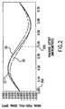
- Figure 2 illustrates the magnitude of RPP as a function of radial offset of the center of the laser spot from the center of a groove, for one particular system.
- Line S1 represents the magnitude of RPP with no disk tilt.
- the system generating the RPP signal illustrated in figure 2 has a track pitch of 0.76 micrometers, so that when the focused laser spot is offset by 0.38 micrometers, the spot is centered on a land (reference 202).
- RPP as a function of radial offset in figure 2 has characteristics that are unique to the present invention.
- the system generating the RPP signal illustrated in figure 2 has been designed so that RPP is insensitive to radial tilt when the focused laser spot is centered on a groove (reference 200). That is, when the focused laser spot is centered on a groove, RPP is zero even if the optical disk is tilted.
- RPP varies with tilt.
- the height of grooves is occasionally changed, thereby providing a measurable step in RPP if the disk is tilted, even if the spot is centered, without affecting the data signal.
- the focused laser spot When the focused laser spot is centered in a groove, and when the disk is not tilted, the spot on the recording thin film structure is symmetrical on the groove, the reflected light is centered in the aperture (figure 1A, 106), and the reflected light is centered on the detector array (figure 1A, 114).
- the disk substrate 120 When the disk is tilted, the disk substrate 120 causes the focused laser spot to become asymmetrical on the groove due to an aberration called coma.
- the asymmetry of the focused spot on the data surface introduces an asymmetry of light distribution within the aperture, and asymmetry of light distribution on the detector array.
- radial disk tilt causes the entire reflected light pattern to shift within the aperture, causing one side of the reflected beam to be vignetted by the aperture.
- Coma and vignetting each change the intensity distribution on the detector array, and the changes can add or cancel.
- the present invention utilizes the fact that the vignetting effects and coma effects can mutually compensate or magnify each other in the RPP signal. As will described below, the net effects of coma and vignetting on RPP may be made to cancel, when the focused spot is centered on a groove, by a proper selection of groove parameters.
- the laser wavelength 650 nanometers
- reflectance 0.2
- track pitch 0.76 micrometers
- groove width 0.38 micrometers
- the aperture is round, and truncates the disk illuminating beam (which has a gaussian distribution) falling outside a boundary representing an intensity of 50% of the peak intensity at the center of the beam.
- the depth of a groove relative to the surface of a land. Recall that the focused spot is distributed over the width of a groove and onto the adjacent lands. Adjusting the groove depth causes the interference patterns on the detector array to change.
- the depth of a groove was empirically adjusted to a depth of 52 nanometers, in an optical modeling program, so that the net effect of coma on RPP was canceled by the net effect of vignetting by the aperture on RPP when the focused spot is centered on a groove.
- RPP is insensitive to radial tilt when the focused laser spot is centered on a groove (figure 2, reference 200) and has increased sensitivity to radial tilt when the focused spot is centered on a land (figure 2, reference 202).
- a land instead of a groove, it is possible to select the disk groove depth so that the RPP signal will be insensitive to radial tilt when the focused spot is centered on a land and will have increased sensitivity to radial tilt when the focused spot is centered on a groove.
- FIG. 3A illustrates an optical disk 110 in accordance with the invention.
- the optical disk 110 includes an inner hole 300 for mounting.
- a data area extends from an inner radius 302 to an outer radius 304.
- the data area may comprise one spiral grove (separated by lands), multiple concentric circular grooves separated by lands, or other arrangements of grooves separated by lands.
- Radial tilt measurement features are provided along multiple radial lines 306, within the data area, wherein the height of grooves and lands are changed. For example, at a radius where there is normally a groove, the recording thin film structure may be fabricated to have the height of a land, and at a radius where there is normally a land, the recording thin film structure may be fabricated to have the height of a groove.
- Figure 3A depicts three radial lines (306), but the number three is not a requirement.
- having the groove height step up and down fewer than three times per revolution of the disk may be sufficient, and for other systems, more than three steps up and down per revolution of the disk may be preferable.
- Stepping the groove height to the height of a land and stepping land height to the height of a groove is convenient for manufacturability, but from figure 2, it can be seen that other steps in groove height and land height are acceptable. The only requirement is that the changes in height result in a detectable step in the RPP signal.
- Figure 3B illustrates an expanded view of the area along a radial line 306 where the grooves and lands have steps in height.
- cross-hatched areas depict surfaces on the recording thin film structure having the height defined as a land
- non-cross-hatched areas depict surfaces on the recording thin film structure having a height defined as a groove.
- reference number 308 designates grooves
- reference number 310 designates lands.
- the height is changed to the height of a land, as designated by reference number 312.
- the circumferential length of the central part of area 312 is less than the shortest length that can be resolved by the optical system, in order to minimize any effect on the data signal by the tilt detection feature.
- Writing and reading data is synchronized with a clock signal.
- a channel bit width is defined as a distance on the data surface determined by one data clock period times the circumferential velocity of the disk.
- the shortest mark that can be resolved by the optical system is about three times the channel bit width.
- a channel bit width is 133 nanometers.
- the circumferential length of the central part of area 312 may be about two channel bit widths, or about 266 nanometers.
- the data signal is a sum (figure 1C, A+B+C+D) and recall that a focused laser spot centered on a groove overlaps onto the adjacent lands.
- the circumferential length of the land segments (area 314) adjacent to the tilt detection features in the groove, and with changed land height, is selected to further reduce any effect on the data signal by the tilt detection features. Since the intensity of the laser spot is substantially lower over the lands relative to the center of the spot, the circumferential length of each area 314 needs to be greater than the circumferential length of each area 312, such that the light reflected from two combined areas 314 on adjacent lands can compensate for any perturbation introduced into the sum data signal by area 312 on the groove. In the system illustrated in figure 3, the circumferential length of the central part of each area 314 is about 5.5 channel bit widths.
- FIG 4 illustrates a radial push-pull signal (RPP) 400 as a function of time when using an optical disk as illustrated in figures 3A and 3B.
- RPP radial push-pull signal
- Optical disk systems commonly also derive a focus error signal from signals from the detector array (figure 1A, 114).
- the focus control similarly as for tracking offset control, is much lower frequency than the data information, so that low pass filtering for the focus control also removes any high frequency steps resulting from the radial tilt measurement features (figure 3B, areas 312 and 314).
- the radial tilt measurement features do not affect data writing. That is, when data is written, the tilt measurement features may be ignored, and data may be written over the tilt measurement features.
- FIG. 5A illustrates a single-spiral groove and land disk 500 having a spiral track 502. The switching point is along a radial line 504.
- Figure 5B provides additional detail of the switching point.
- groove 506 changes to a land 508, and land 510 changes to a groove 512.
- a disk as illustrated in figures 5A and 5B may be designed so that a tracking error signal is insensitive to tilt when the focused laser spot is centered on a groove (or land).
- the disk if the disk is not tilted, switching from position 200 to position 202 does not result in a step in the tracking offset signal. However, if the disk is tilted, the switching point then provides a single abrupt step in the tracking error signal, once every revolution.
- the tracking signal may exhibit a positive step when switching from a groove to a land, and then one revolution later the tracking signal may exhibit a negative step when switching from a land to a groove, if the disk is radially tilted.
- curves S2 and S3 may be shifted horizontally so that, for example, at position 200, curve S2 is above curve S1 and curve S3 is below curve S1, and at position 202, curve S2 is below curve S1 and curve S3 is above curve S1, with the magnitudes of the differences equal. Then, an abrupt step in the tracking error signal occurs when the focused spot transitions from a groove to a land, and vice-versa, and if there is no radial tilt, the steps are equal in magnitude but opposite in direction. However, when the disk is radially tilted, the steps have unequal magnitude.
Landscapes
- Optical Recording Or Reproduction (AREA)
- Optical Record Carriers And Manufacture Thereof (AREA)
Abstract
Description
Claims (10)
- An optical disk medium (110) comprising:a data surface, the data surface having at least one groove (124, 308) at a radial distance from a center of the disk, the groove at a groove height; and,a radial tilt measurement area (312) in the groove, having a height that is different than the groove height, the radial tilt measurement area in the groove having a circumferential length that is less than a circumference of the disk at the radial distance of the groove.
- The optical disk of claim 1, further comprising:the data surface having lands (126, 310) adjacent to the groove, at a land height; and,a radial tilt measurement area (314) on each land, adjacent to the radial tilt measurement area (312) in the groove, having a height that is different than the land height.
- The optical disk of claim 2, wherein the height of the radial tilt measurement area (312) in the groove is the land height and the height of the tilt measurement area (314) in each land is the groove height.
- The optical disk of claim 1, wherein the data surface is adapted to receive data marks, the data marks having a specified shortest data mark length, and wherein the radial tilt measurement area in the groove has a circumferential length that is less than the specified shortest data mark length.
- A disk system comprising:an optical disk (110) having a data surface;a radial tilt measurement area (312, 314) on the data surface of the optical disk, the tilt measurement area comprising an area having an abrupt change in height;an optical system (116), including a light source (100) and an optical detector array (114), wherein light from the light source is focused onto the data surface of the optical disk and light reflected from the data surface is directed onto the optical detector array, and wherein a plurality of signals are generated by the detector array;an electronics system (117), deriving a tacking error signal (figure 2, S1; figure 4, 400) from the plurality of signals from the detector array;
wherein when light is reflected from the radial tilt measurement area on the data surface onto the detector array, and when the disk is locally radially tilted, a detectable magnitude change occurs in the tracking error signal (figure 2, S2, S3; figure 4, 402, 404); andthe electronics system measuring radial tilt from the detectable magnitude change in the tracking error signal. - The disk system of claim 5, further comprising:an optical aperture (106), wherein light reflected from the data surface passes through the optical aperture before being directed onto the detector array.
- The disk system of claim 5, further comprising:the data surface having at least one groove (124, 308), the groove having a groove height, the radial tilt measurement area (312) located on the groove, the radial tilt measurement area comprising an area having a height that is different than the groove height.
- The disk system of claim 7, further comprising:the data surface having lands (126, 310) adjacent to the groove, at a land height; and,along a radial line (306) passing through the tilt measurement area on the groove, a tilt measurement area (314) on each land, having a height that is different than the land height.
- The disk system of claim 8, wherein the height of the radial tilt measurement area on the groove is the land height and the height of the radial tilt measurement area on each land is the groove height.
- A method of measuring radial tilt of an optical disk (110), the method comprising the following steps:detecting light reflected from the optical disk;deriving a tracking error signal (figure 2, S1; figure 4, 400) from the detected reflected light; and,detecting an abrupt step in the magnitude of the tracking error signal (figure 2, S2, S3; figure 4, 402, 404), the magnitude of the abrupt step indicating a magnitude of radial tilt.
Applications Claiming Priority (2)
| Application Number | Priority Date | Filing Date | Title |
|---|---|---|---|
| US09/256,791 US6549511B1 (en) | 1999-02-24 | 1999-02-24 | Optical disk medium having features for radial tilt detection and apparatus for measuring radial tilt |
| US256791 | 1999-02-24 |
Publications (3)
| Publication Number | Publication Date |
|---|---|
| EP1031970A2 true EP1031970A2 (en) | 2000-08-30 |
| EP1031970A3 EP1031970A3 (en) | 2002-01-23 |
| EP1031970B1 EP1031970B1 (en) | 2005-10-12 |
Family
ID=22973594
Family Applications (1)
| Application Number | Title | Priority Date | Filing Date |
|---|---|---|---|
| EP00301412A Expired - Lifetime EP1031970B1 (en) | 1999-02-24 | 2000-02-23 | Optical disk medium having features for radial tilt detection and apparatus for measuring radial tilt |
Country Status (6)
| Country | Link |
|---|---|
| US (1) | US6549511B1 (en) |
| EP (1) | EP1031970B1 (en) |
| JP (1) | JP2000251333A (en) |
| KR (1) | KR20000057116A (en) |
| DE (1) | DE60023050T2 (en) |
| TW (1) | TW454182B (en) |
Cited By (4)
| Publication number | Priority date | Publication date | Assignee | Title |
|---|---|---|---|---|
| WO2003025499A1 (en) * | 2001-09-17 | 2003-03-27 | Sharp Kabushiki Kaisha | Tilt sensing apparatus |
| KR100403926B1 (en) * | 2000-09-01 | 2003-10-30 | 삼성전기주식회사 | Radial Tilt Detector |
| EP1457973A2 (en) | 2003-03-10 | 2004-09-15 | Nec Corporation | Optical disk medium and optical disk recording/reproducing apparatus |
| WO2004094946A1 (en) * | 2003-04-22 | 2004-11-04 | Hentze-Lissotschenko Patentverwaltungs Gmbh & Co. Kg | Arrangement and method for adjusting at least one component of a light-generating device |
Families Citing this family (9)
| Publication number | Priority date | Publication date | Assignee | Title |
|---|---|---|---|---|
| KR100396544B1 (en) * | 2000-11-17 | 2003-09-02 | 삼성전자주식회사 | Apparatus for detecting error signal in optical recording/reproducing system |
| US11337728B2 (en) | 2002-05-31 | 2022-05-24 | Teleflex Life Sciences Limited | Powered drivers, intraosseous devices and methods to access bone marrow |
| US8668698B2 (en) | 2002-05-31 | 2014-03-11 | Vidacare Corporation | Assembly for coupling powered driver with intraosseous device |
| IL165224A0 (en) | 2002-05-31 | 2005-12-18 | Vidacare Corp | Apparatus and method to access bone marrow |
| US8641715B2 (en) | 2002-05-31 | 2014-02-04 | Vidacare Corporation | Manual intraosseous device |
| US10973545B2 (en) | 2002-05-31 | 2021-04-13 | Teleflex Life Sciences Limited | Powered drivers, intraosseous devices and methods to access bone marrow |
| US9504477B2 (en) | 2003-05-30 | 2016-11-29 | Vidacare LLC | Powered driver |
| US8944069B2 (en) | 2006-09-12 | 2015-02-03 | Vidacare Corporation | Assemblies for coupling intraosseous (IO) devices to powered drivers |
| CN117330181B (en) * | 2023-12-01 | 2024-02-27 | 中国工程物理研究院应用电子学研究所 | Multi-channel multi-functional laser beam quality detection system based on metasurface |
Family Cites Families (15)
| Publication number | Priority date | Publication date | Assignee | Title |
|---|---|---|---|---|
| CA1165871A (en) * | 1978-11-08 | 1984-04-17 | Kornelis Bulthuis | Optically inscribable record carrier |
| NL7906576A (en) * | 1979-09-03 | 1981-03-05 | Philips Nv | REGISTRATION HOLDER IN WHICH INFORMATION HAS BEEN INCLUDED IN AN OPTICALLY READABLE INFORMATION STRUCTURE AND READING DEVICE THEREFOR. |
| NL7907180A (en) * | 1979-09-27 | 1981-03-31 | Philips Nv | RECORD CONTAINER IN WHICH INFORMATION HAS BEEN INCLUDED IN AN OPTICALLY READABLE INFORMATION STRUCTURE AND EQUIPMENT FOR READING IT. |
| NL8100098A (en) * | 1981-01-12 | 1982-08-02 | Philips Nv | RECORD CARRIER WITH OPTICALLY READABLE INFORMATION STRUCTURE. |
| JPS5919250A (en) | 1982-07-21 | 1984-01-31 | Hitachi Ltd | Recording and reproducing device of optical information |
| NL8500152A (en) * | 1985-01-22 | 1986-08-18 | Philips Nv | REGISTRATION CARRIER BODY INCLUDING PRE-APPLIED AND OPTICALLY DETECTABLE SERVOSCORE PARTS AND SECTOR ADDRESSES. |
| US4866688A (en) | 1985-12-20 | 1989-09-12 | Hitachi, Ltd. | Composite tracking servo system for optical disc apparatus with track offset correction |
| US5602824A (en) * | 1994-08-12 | 1997-02-11 | Nikon Corporation | Optical disk capable of recording information on both land and groove tracks |
| EP0709834B1 (en) | 1994-10-31 | 2000-05-24 | Matsushita Electric Industrial Co., Ltd. | Tilt sensor, optical disk, and tilt compensating method for performing a stable tilt compensating control, and apparatus utilizing the same |
| KR100230250B1 (en) | 1994-12-26 | 1999-11-15 | 윤종용 | Method and apparatus for correcting aberration by tilting optical disc |
| JP2738337B2 (en) * | 1995-03-31 | 1998-04-08 | 日本電気株式会社 | Optical reproducing medium reproducing method and reproducing apparatus |
| JP3560410B2 (en) | 1996-03-25 | 2004-09-02 | 三菱電機株式会社 | Optical disk device and optical disk |
| US5808985A (en) | 1997-04-07 | 1998-09-15 | Eastman Kodak Company | Tilt error signal producing apparatus using multiple tracking error signals |
| JP3211002B2 (en) * | 1997-04-24 | 2001-09-25 | 富士通株式会社 | Optical recording medium, tilt detector, optical disk device, tilt detection method, and tilt correction method |
| JPH1116216A (en) | 1997-06-19 | 1999-01-22 | Sony Corp | Optical disk and optical disk device |
-
1999
- 1999-02-24 US US09/256,791 patent/US6549511B1/en not_active Expired - Fee Related
- 1999-09-27 TW TW088116528A patent/TW454182B/en not_active IP Right Cessation
- 1999-12-29 KR KR1019990064533A patent/KR20000057116A/en not_active Ceased
-
2000
- 2000-02-14 JP JP2000034585A patent/JP2000251333A/en active Pending
- 2000-02-23 EP EP00301412A patent/EP1031970B1/en not_active Expired - Lifetime
- 2000-02-23 DE DE60023050T patent/DE60023050T2/en not_active Expired - Lifetime
Cited By (7)
| Publication number | Priority date | Publication date | Assignee | Title |
|---|---|---|---|---|
| KR100403926B1 (en) * | 2000-09-01 | 2003-10-30 | 삼성전기주식회사 | Radial Tilt Detector |
| WO2003025499A1 (en) * | 2001-09-17 | 2003-03-27 | Sharp Kabushiki Kaisha | Tilt sensing apparatus |
| US7019280B2 (en) | 2001-09-17 | 2006-03-28 | Sharp Kabushiki Kaisha | Apparatus for detecting the tilt of a light reflector relative to the optical axis of input light |
| EP1457973A2 (en) | 2003-03-10 | 2004-09-15 | Nec Corporation | Optical disk medium and optical disk recording/reproducing apparatus |
| EP1457973A3 (en) * | 2003-03-10 | 2006-11-02 | Nec Corporation | Optical disk medium and optical disk recording/reproducing apparatus |
| US7336576B2 (en) | 2003-03-10 | 2008-02-26 | Kabushiki Kaisha Toshiba | Optical disk medium and optical disk recording/reproducing apparatus utilizing tilt detection areas having special marks |
| WO2004094946A1 (en) * | 2003-04-22 | 2004-11-04 | Hentze-Lissotschenko Patentverwaltungs Gmbh & Co. Kg | Arrangement and method for adjusting at least one component of a light-generating device |
Also Published As
| Publication number | Publication date |
|---|---|
| KR20000057116A (en) | 2000-09-15 |
| EP1031970A3 (en) | 2002-01-23 |
| JP2000251333A (en) | 2000-09-14 |
| DE60023050D1 (en) | 2006-02-23 |
| DE60023050T2 (en) | 2006-09-28 |
| EP1031970B1 (en) | 2005-10-12 |
| US6549511B1 (en) | 2003-04-15 |
| TW454182B (en) | 2001-09-11 |
Similar Documents
| Publication | Publication Date | Title |
|---|---|---|
| US5084860A (en) | Apparatus for optical disc memory with correction pattern and master disc cutting apparatus | |
| EP0752701B1 (en) | An optical information recording medium and an optical information recording/reproducing device | |
| KR100377647B1 (en) | Optical recording method using land/groove recording | |
| EP1205923B1 (en) | Aberration correction method and optical disk apparatus | |
| US6487147B2 (en) | Optical information recording medium and an optical information recording/reproduction device | |
| US6137758A (en) | Optical disc discriminating apparatus | |
| EP1031970B1 (en) | Optical disk medium having features for radial tilt detection and apparatus for measuring radial tilt | |
| EP0813193B1 (en) | Optical disk | |
| AU6201799A (en) | Method and apparatus for generating focus error signals in multi-beam optical disk drive | |
| US6404729B1 (en) | Optical disc | |
| KR100633476B1 (en) | Optical record carrier | |
| US20020127365A1 (en) | Optical recording medium | |
| US6744706B2 (en) | Optical system with tracking controller | |
| US6314067B1 (en) | Optical disk having pattern for tilt detection | |
| KR100458727B1 (en) | Optical recording media | |
| EP1457973B1 (en) | Optical disk medium and optical disk recording/reproducing apparatus | |
| EP1708177B1 (en) | Method for reading media information from optical recording media | |
| EP1063642B1 (en) | Optical recording medium | |
| EP1526516B1 (en) | Optical recording medium, substrate for optical recording medium and optical disk device | |
| KR100265886B1 (en) | High Density Optical Disks and Manufacturing Method Thereof | |
| US6424612B1 (en) | Reproducing method and apparatus for optical disk | |
| JP2002298395A (en) | Tracking error detection method and device | |
| JP2667685B2 (en) | Optical memory device and tracking error detection method for optical memory device | |
| US20050128933A1 (en) | Optical disk | |
| HK1073527A1 (en) | Recording medium and recording system for the recording medium |
Legal Events
| Date | Code | Title | Description |
|---|---|---|---|
| PUAI | Public reference made under article 153(3) epc to a published international application that has entered the european phase |
Free format text: ORIGINAL CODE: 0009012 |
|
| AK | Designated contracting states |
Kind code of ref document: A2 Designated state(s): AT BE CH CY DE DK ES FI FR GB GR IE IT LI LU MC NL PT SE Kind code of ref document: A2 Designated state(s): DE FR GB |
|
| AX | Request for extension of the european patent |
Free format text: AL;LT;LV;MK;RO;SI |
|
| RAP1 | Party data changed (applicant data changed or rights of an application transferred) |
Owner name: HEWLETT-PACKARD COMPANY, A DELAWARE CORPORATION |
|
| PUAL | Search report despatched |
Free format text: ORIGINAL CODE: 0009013 |
|
| AK | Designated contracting states |
Kind code of ref document: A3 Designated state(s): AT BE CH CY DE DK ES FI FR GB GR IE IT LI LU MC NL PT SE |
|
| AX | Request for extension of the european patent |
Free format text: AL;LT;LV;MK;RO;SI |
|
| RIC1 | Information provided on ipc code assigned before grant |
Free format text: 7G 11B 7/007 A, 7G 11B 7/095 B, 7G 11B 7/09 B, 7G 11B 11/105 B |
|
| 17P | Request for examination filed |
Effective date: 20020531 |
|
| AKX | Designation fees paid |
Free format text: DE FR GB |
|
| GRAP | Despatch of communication of intention to grant a patent |
Free format text: ORIGINAL CODE: EPIDOSNIGR1 |
|
| GRAS | Grant fee paid |
Free format text: ORIGINAL CODE: EPIDOSNIGR3 |
|
| GRAA | (expected) grant |
Free format text: ORIGINAL CODE: 0009210 |
|
| AK | Designated contracting states |
Kind code of ref document: B1 Designated state(s): DE FR GB |
|
| REG | Reference to a national code |
Ref country code: GB Ref legal event code: FG4D |
|
| REF | Corresponds to: |
Ref document number: 60023050 Country of ref document: DE Date of ref document: 20060223 Kind code of ref document: P |
|
| ET | Fr: translation filed | ||
| PLBE | No opposition filed within time limit |
Free format text: ORIGINAL CODE: 0009261 |
|
| STAA | Information on the status of an ep patent application or granted ep patent |
Free format text: STATUS: NO OPPOSITION FILED WITHIN TIME LIMIT |
|
| 26N | No opposition filed |
Effective date: 20060713 |
|
| REG | Reference to a national code |
Ref country code: GB Ref legal event code: 732E Free format text: REGISTERED BETWEEN 20120329 AND 20120404 |
|
| PGFP | Annual fee paid to national office [announced via postgrant information from national office to epo] |
Ref country code: FR Payment date: 20130408 Year of fee payment: 14 Ref country code: GB Payment date: 20130129 Year of fee payment: 14 Ref country code: DE Payment date: 20130124 Year of fee payment: 14 |
|
| REG | Reference to a national code |
Ref country code: DE Ref legal event code: R119 Ref document number: 60023050 Country of ref document: DE |
|
| GBPC | Gb: european patent ceased through non-payment of renewal fee |
Effective date: 20140223 |
|
| REG | Reference to a national code |
Ref country code: FR Ref legal event code: ST Effective date: 20141031 |
|
| REG | Reference to a national code |
Ref country code: DE Ref legal event code: R119 Ref document number: 60023050 Country of ref document: DE Effective date: 20140902 |
|
| PG25 | Lapsed in a contracting state [announced via postgrant information from national office to epo] |
Ref country code: GB Free format text: LAPSE BECAUSE OF NON-PAYMENT OF DUE FEES Effective date: 20140223 Ref country code: DE Free format text: LAPSE BECAUSE OF NON-PAYMENT OF DUE FEES Effective date: 20140902 Ref country code: FR Free format text: LAPSE BECAUSE OF NON-PAYMENT OF DUE FEES Effective date: 20140228 |