EP1031957A2 - Desensitized price label - Google Patents
Desensitized price label Download PDFInfo
- Publication number
- EP1031957A2 EP1031957A2 EP00300431A EP00300431A EP1031957A2 EP 1031957 A2 EP1031957 A2 EP 1031957A2 EP 00300431 A EP00300431 A EP 00300431A EP 00300431 A EP00300431 A EP 00300431A EP 1031957 A2 EP1031957 A2 EP 1031957A2
- Authority
- EP
- European Patent Office
- Prior art keywords
- label
- strip
- tag
- adhesive
- barrier
- Prior art date
- Legal status (The legal status is an assumption and is not a legal conclusion. Google has not performed a legal analysis and makes no representation as to the accuracy of the status listed.)
- Granted
Links
Images


Classifications
-
- G—PHYSICS
- G09—EDUCATION; CRYPTOGRAPHY; DISPLAY; ADVERTISING; SEALS
- G09F—DISPLAYING; ADVERTISING; SIGNS; LABELS OR NAME-PLATES; SEALS
- G09F3/00—Labels, tag tickets, or similar identification or indication means; Seals; Postage or like stamps
- G09F3/08—Fastening or securing by means not forming part of the material of the label itself
- G09F3/18—Casings, frames or enclosures for labels
- G09F3/20—Casings, frames or enclosures for labels for adjustable, removable, or interchangeable labels
- G09F3/208—Electronic labels, Labels integrating electronic displays
-
- G—PHYSICS
- G09—EDUCATION; CRYPTOGRAPHY; DISPLAY; ADVERTISING; SEALS
- G09F—DISPLAYING; ADVERTISING; SIGNS; LABELS OR NAME-PLATES; SEALS
- G09F3/00—Labels, tag tickets, or similar identification or indication means; Seals; Postage or like stamps
- G09F3/08—Fastening or securing by means not forming part of the material of the label itself
- G09F3/10—Fastening or securing by means not forming part of the material of the label itself by an adhesive layer
-
- G—PHYSICS
- G09—EDUCATION; CRYPTOGRAPHY; DISPLAY; ADVERTISING; SEALS
- G09F—DISPLAYING; ADVERTISING; SIGNS; LABELS OR NAME-PLATES; SEALS
- G09F3/00—Labels, tag tickets, or similar identification or indication means; Seals; Postage or like stamps
- G09F3/08—Fastening or securing by means not forming part of the material of the label itself
- G09F3/18—Casings, frames or enclosures for labels
- G09F3/20—Casings, frames or enclosures for labels for adjustable, removable, or interchangeable labels
- G09F3/204—Casings, frames or enclosures for labels for adjustable, removable, or interchangeable labels specially adapted to be attached to a shelf or the like
-
- Y—GENERAL TAGGING OF NEW TECHNOLOGICAL DEVELOPMENTS; GENERAL TAGGING OF CROSS-SECTIONAL TECHNOLOGIES SPANNING OVER SEVERAL SECTIONS OF THE IPC; TECHNICAL SUBJECTS COVERED BY FORMER USPC CROSS-REFERENCE ART COLLECTIONS [XRACs] AND DIGESTS
- Y10—TECHNICAL SUBJECTS COVERED BY FORMER USPC
- Y10T—TECHNICAL SUBJECTS COVERED BY FORMER US CLASSIFICATION
- Y10T428/00—Stock material or miscellaneous articles
- Y10T428/14—Layer or component removable to expose adhesive
- Y10T428/1486—Ornamental, decorative, pattern, or indicia
-
- Y—GENERAL TAGGING OF NEW TECHNOLOGICAL DEVELOPMENTS; GENERAL TAGGING OF CROSS-SECTIONAL TECHNOLOGIES SPANNING OVER SEVERAL SECTIONS OF THE IPC; TECHNICAL SUBJECTS COVERED BY FORMER USPC CROSS-REFERENCE ART COLLECTIONS [XRACs] AND DIGESTS
- Y10—TECHNICAL SUBJECTS COVERED BY FORMER USPC
- Y10T—TECHNICAL SUBJECTS COVERED BY FORMER US CLASSIFICATION
- Y10T428/00—Stock material or miscellaneous articles
- Y10T428/14—Layer or component removable to expose adhesive
- Y10T428/149—Sectional layer removable
-
- Y—GENERAL TAGGING OF NEW TECHNOLOGICAL DEVELOPMENTS; GENERAL TAGGING OF CROSS-SECTIONAL TECHNOLOGIES SPANNING OVER SEVERAL SECTIONS OF THE IPC; TECHNICAL SUBJECTS COVERED BY FORMER USPC CROSS-REFERENCE ART COLLECTIONS [XRACs] AND DIGESTS
- Y10—TECHNICAL SUBJECTS COVERED BY FORMER USPC
- Y10T—TECHNICAL SUBJECTS COVERED BY FORMER US CLASSIFICATION
- Y10T428/00—Stock material or miscellaneous articles
- Y10T428/15—Sheet, web, or layer weakened to permit separation through thickness
Definitions
- the present invention relates generally to electronic price tags, and, more specifically, to face labels therefor.
- a merchandising store such as a grocery supermarket, displays items for sale on shelves, with a price label being provided for identifying the product by description, measure, and price.
- electronic price labels have been developed and are in current use at various locations.
- the electronic price label comprises a thin rectangular tag having face and back sides, and suitable low-power electronics therein.
- the EPL tag has a visual electronic display, such as a conventional liquid crystal display (LCD), which may operate continuously for an extended period of time on battery power.
- the display typically includes multiple digits for displaying the desired retail price and unit price for example.
- Each tag is programmed during manufacture for providing a unique serial number, with each tag also including a back label for identifying the programmed serial number, typically in barcode form.
- each tag is associated with a given product and includes a face label identifying the corresponding product and pricing information.
- a typical face label is pre-printed to identify the product, the universal product code (UPC) or SKU barcode, and the name of the store.
- a typical face label is a pressure sensitive label initially affixed to a release liner by an adhesive.
- the label is peeled from the liner and bonded atop the EPL tag using the same adhesive provided therewith.
- U.S. Patent 5,619,416 discloses a system and method for automatically labeling the EPL tags.
- the face label includes a patch or strip which is initially bonded atop the tag display when the label is applied to the tag.
- the strip is printed during the application process with variable data such as a record number (RN) in barcode form corresponding with the specific product associated with the EPL tag.
- RN record number
- the strip is peeled away from the label and underlying tag display, with the RN barcode being read for correlating the installed tag with the corresponding product.
- the removed strip then exposes the tag display which is programmed for the retail and unit price of the corresponding product for being seen by store customers.
- the label strip is eventually removed from the label after being attached to the EPL tag, it must be sufficiently secured to the label for undergoing the various steps during manufacture, printing, and application of the label without being prematurely liberated therefrom. Since the back side of the label and strip is covered by adhesive, premature liberation of a strip not only causes a defective label but may also inadvertently attach to processing equipment possibly causing jamming thereof.
- removal of the strip from the tag display may cause tearing of the strip itself or leave behind portions thereof including adhesive which must be suitably removed in a subsequent operation increasing the time and expense of label application.
- an integral push button is provided on the face of the tag near the visual display which may be used by a clerk or customer for accessing additional data from the tag for visual display when the button is pushed.
- the face label is adhesively bonded atop the push button in one configuration, and the adhesive atop the push button may cause interference with the operation of the push button over time.
- a label for an electronic price tag includes an opposite face and back, and a border surrounding a removable strip for overlaying a visual display of the tag.
- An adhesive is disposed on the label back for bonding the label to the tag.
- a barrier is disposed on the adhesive under the strip for desensitizing adhesion of the strip with the tag display. The strip is readily removable from the label and display since the barrier degrades adhesive effectiveness.
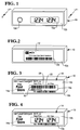
- FIG. 1 Illustrated in Figure 1 is an exemplary EPL tag 10 in rectangular form.
- the tag is conventional and includes a visual electronic display 10a in the exemplary form of a liquid crystal display (LCD) on a front face or side 10b thereof.
- LCD liquid crystal display
- the inside of the tag includes suitable, programmable electronics which are battery powered to operate the display.
- the tag may be programmed to display numbers indicative of retail price and unit price for a specific product, for example.
- the tag electronics include a suitable memory for storing desired information therein, and a radio receiver for remotely reprogramming the tag for changing pricing information, for example.
- the memory is programmed at manufacture to include a unique serial number for identifying the tag, and for correlating a specific product and price therefor associated with the specific tag and corresponding product.
- a suitable identification label 12 as illustrated in Figure 2 is secured to any suitable location thereon such as its back face or side 10c.
- the back label may include any desired information including identification of the tag manufacturer, and an identification barcode 12a identifying the tag and including at least in part the serial number programmed in the tag.
- a suitable face label 14 may include, for example, a printed product description, a unit of measure, and size.
- the face label may also include additional information as desired such as the name of the specific store, trademark, and artistic display.
- the label may also include a conventional UPC or SKU number in barcode form.
- the face label includes a patch or ship 14a on which a unique record number 16 in barcode form, for example, may be printed.
- the strip 14a is preferably sized to match the perimeter of the visual display 10a illustrated in Figure 1 so that it may be manually peeled or torn away from the tag to expose the visual display as illustrated in Figure 4.
- the tag 10 illustrated in Figure 4 is in final form with its attached face label 14 for identifying the product associated therewith in a merchandising store when attached to its specific shelf location.
- U.S. Patent 5,619,416 identified above discloses a system and method for automatically labeling a series of the EPL tags with corresponding face labels for correlating specific products with corresponding tags.
- the present invention is an improvement in the labeling system of that patent for solving problems associated with the adhesive found on the back of the face label 14 provided for bonding the label to the front of the tag.
- Figure 5 illustrates an exemplary face label 14 prior to application to the tag 10.
- the label includes the removable strip 14a surrounded by a border 14b.
- the strip has a rectangular configuration to match the corresponding rectangular configuration of the tag display 10a to initially overlay that tag display during the assembly process as illustrated in Figure 3.
- the face label 14 is in the form of a panel or sheet having any suitable material composition such as polyolefin for its resistance to tearing.
- the label has a face 14c and back 14d on opposite sides or surfaces thereof, and as additionally shown in Figure 6.
- the label is preferably in the form of a pressure sensitive label having a suitable adhesive 18 disposed or coated over the entire label back 14d which is subsequently used for bonding the label to the front of the tag 10.
- a first barrier 20 is disposed or coated on the adhesive 18 under the strip 14a for desensitizing or degrading adhesion of the strip 14a with the tag display 10a when initially bonded thereto as illustrated in Figure 3.
- the strip may be readily removed from the label border and tag for uncovering the tag display 10a illustrated in Figure 4.
- the barrier 20 substantially reduces the likelihood of inadvertent tearing of the strip 14a as it is removed from the tag, and ensures that none of the adhesive 18 remains atop the tag display which would require subsequent cleaning thereof.
- a die-cut 22 severs the strip 14a from the border 14b and is formed in any conventional manner.
- the die-cut 22 preferably extends completely or continuously around the perimeter of the strip 14a except for a plurality of interruptions in the die-cut which define respective ties 24.
- the barrier 20 preferably fully covers the adhesive 18 within the perimeter of the strip 14a bounded by the die-cut 22. Since the barrier 20 degrades the adhesion of the adhesive 18 under the strip 14a, and since the die-cuts 22 sever the strip from the label border, the ties 24 are introduced for maintaining structural integrity of the label during the manufacturing and application process to prevent premature liberation of the strip prior to final removal of the strip itself.
- the label 14 is initially formed in a laminate including a release liner 26 which is removably bonded to the label back 14d by the adhesive 18.
- the release liner 26 may have any conventional form, and is typically a silicone impregnated paper having limited adhesion to the adhesive 18.
- the label laminate is typically obtained from a manufacturer with face stock being adhesively bonded to the liner for use in subsequent manufacturing steps which size and cut individual labels to desired form, and print the labels with any suitable information.
- Pressure sensitive labels of this type are well known in the commercial field, with individual labels being readily removed from the liner by peeling therefrom and rebonded to any desired object using the same adhesive already coating the back of the label.
- the adhesive's bond with the liner is substantially reduced or eliminated.
- adhesion of the barrier coated strip 14a is also degraded or eliminated when the label is removed from the liner and applied atop the tag illustrated in Figure 3. This permits the strip 14a to be subsequently removed from the tag with substantially little or no resistance as compared to the construction without the barrier 18 as indicated above.
- the ties 24 interrupting the perimeter die-cut 22 offset the loss of adhesion to the liner introduced by the barrier 18.
- the tag 10 preferably also includes a push button 10d at any suitable location adjacent the display 10a.
- the push button may have any conventional form and is operatively joined to the electronics inside the tag for changing the information presented on the display 10a.
- a store clerk may push the button 10d for temporarily displaying a regular price when the associated product is on sale at a reduced price.
- the push button 10d is hidden behind the label 14 as illustrated in Figure 4, and may be activated by pushing a corresponding spot 14e of the label border 14b under which the button is hidden.
- pushing the spot 14e repetitively over time can lead to malfunction of push button operation due to the adhesive commonly used in pressure sensitive labels.
- another feature of this embodiment of the present invention is the use of a second barrier 20b disposed on the adhesive 18, as illustrated in Figure 6, directly under the spot 14e of the border, as illustrated in Figure 5.
- the spot barrier 20b is similarly used for desensitizing or degrading adhesion of the adhesive underlying the spot 14e with the push button 10d located therebelow.
- the spot barrier uncouples the spot 14e from the push button so that the adhesive under the spot does not bond the spot to the push button for permitting unobstructed use thereof. And, over repeated pushing of the spot 14e, operation of the push button is not compromised by the adhesive 18.
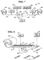
- Figure 7 illustrates schematically an apparatus and method for making the labels 14 illustrated in Figures 5 and 6 in one embodiment.
- the method begins by providing a continuous web 28 of label face sheet or laminate 28a adhesively bonded to a release liner 28b.
- the web 28 is typically obtained from a commercial vendor in the form of an unprinted blank roll 28c in which the adhesive 18 is disposed between the laminate and liner in an integral construction.
- the blank roll 28c is mounted in a conventional label press 30 which includes a first printer 30a which prints atop the laminate 28a any desired information, such the information printed on the label border 14b illustrated in Figure 3.
- the press further includes a delaminator 30b which is conventionally configured for delaminating the laminate 28a, with the adhesive 18 thereon, from the liner 28b in a continuous operation.
- a second printer 30c is then used for applying or printing the barrier 20,20b selectively on the adhesive 18 in a series of spaced apart barriers along the laminate which correspond with a series of labels thereon.
- the barrier 20 is in the preferred form of a desensitizing ink having any conventional composition for being readily printed on the adhesive 18 underlying the laminate 28a.
- the second printer 30c is conventional and may be used to accurately print the desensitizing ink barrier in any desired configuration below the laminate 28a. In this way, both the strip barrier 20 configured for underlying the entire rectangular extent of the label strip 14a and the spot barrier 20b configured for underlying the label spot 14e may be precisely positioned.
- a relaminator 30d is then used for conventionally relaminating the laminate 28a and liner 28b using the same adhesive 18 bonded to the laminate to again form the integral web 28 having printing atop the laminate 28a and therebelow between the underlying adhesive 18 and the liner 28b.
- each strip 14a is configured to overlay respective ones of the displays 10a of a number of tags 10.
- the die-cutter 30e illustrated in Figure 7 die-cuts the leading and trailing edges of each label 14 along the running axis 32 as illustrated in Figure 8 to sever adjacent ones of the labels 14 for permitting their subsequent removal from the underlying web liner 28.
- the labels 14 are interconnected by the web liner 28 in a series along the running axis 32.
- the processed label roll 28d illustrated in Figure 7 is then installed in a third printer 34 for printing any variable data on the corresponding labels 14, such as the RN barcode 16 printed atop the label strips 14a as illustrated in Figure 3.
- the web 28 travels through a conventional label applicator 36 which removes the individual labels 14 from the web liner 28b and applies the labels 14 in turn atop corresponding ones of the EPL tags 10 suitably conveyed therebelow.
- the web liner 28b is removed from the web laminate 28a, and the individual die-cut labels 14 are applied to respective ones of the tags 10 in the label applicator 36.
- the corresponding strips 14a then cover the respective tag displays 10a as shown for the exemplary tag illustrated in Figure 3.
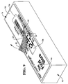
- the individual strips 14a may then be removed from the corresponding labels 14 atop the tags 10 as illustrated in Figure 9 to expose to view the tag displays 10a therebelow.
- FIG. 3 An exemplary one of the tags 10 on which is applied a corresponding label 14 is illustrated in Figures 3 and 9.
- the ties 24 ensure that the respective strips 14a remain attached to the label borders 14b during the printing, cutting, and application operations without being prematurely liberated from the label. Since the labels are formed in a series along the running axis of the continuous web 28, the ties 24 illustrated in Figure 3 are preferably disposed at the leading and trailing edges of each of the strips 14a which is relative to the running axis 32 illustrated in Figures 7 and 8 along which the individual labels are formed.
- each of the strips 14a should include only two of the ties 22 centered on the opposite leading and trailing edges thereof for best maintaining integrity of the strip 14a and surrounding border 14b during the processing thereof.
- the ties are readily broken as the individual strip 14a is peeled away from its border to expose the underlying tag display 10a, as illustrated in Figure 9. In other embodiments, more or less ties may be used at different locations.
- the label 14 is securely bonded to the tag except between the strip 14a and the display 10a, and except between the spot 14e and the underlying push button 10d.
- the improved label described above has several advantages.
- the labels may be manufactured in a series on the roll webs 28 for increased speed.
- the integrated label strips 14a and the label borders 14b remain attached together by the ties 24 atop the underlying web liner 28 for permitting variable printing in the printer 34 and the individual application of the labels 14 to corresponding tags 10 as illustrated in Figure 8.
- the individual label strips 14a may be dedicated for printing any desired variable data such as the RN barcode, with the strips remaining attached to the adjoining label borders even during the dispensing and application of the labels atop the tags 10.
- the label strips 14a are readily removed from the individual tags 10 by peeling therefrom and severing of the ties 24.
- the strip barrier 20 ensures that no adhesive or portions of the strip 14a remain attached to the tag display 10a.
- the spot barrier 20b maintains the functionality of the push button 10d notwithstanding the overlying label border and adhesive thereon. Pushing the label spot 14e in turn depresses the push button 10d without interference by the label adhesive, and the spot barrier 20b prevents interference of push button operation over an extended period.
Landscapes
- Physics & Mathematics (AREA)
- General Physics & Mathematics (AREA)
- Engineering & Computer Science (AREA)
- Theoretical Computer Science (AREA)
- Making Paper Articles (AREA)
- Labeling Devices (AREA)
Abstract
Description
Claims (14)
- A label for an electronic price tag having a visual display, comprising:a border surrounding a removable strip, with a face and back on opposite sides thereof, and with said strip being configured to overlay said tag display;an adhesive disposed on said label back for bonding said label to said tag; anda barrier disposed on said adhesive under said strip for desensitizing adhesion of said strip with said tag display.
- A label as claimed in claim 1 comprising a die-cut severing said strip from said border wherein:said die-cut extends completely around a perimeter of said strip except for a plurality of interruptions defining respective ties; andsaid barrier covers said adhesive within said strip perimeter.
- A label as claimed in claim 1 or claim 2 wherein said tag includes a push button adjacent said display, and further comprising another barrier disposed on said adhesive under a spot of said border for desensitizing adhesion of said spot with said push button.
- A label as claimed in any preceding claim wherein said barriers comprise desensitizing ink.
- A label as claimed in any preceding claims disposed in a series of labels interconnected along a running axis, and wherein said ties are disposed at leading and trailing edges of said strips.
- A label as claimed in any preceding claim wherein said strip includes only two of said ties centered on opposite sides thereof.
- A label as claimed in any preceding claim comprising a liner removably bonded to said label back by said adhesive.
- A method of making a label for an electronic price tag having a visual display, comprising:providing a web of label laminate adhesively bonded to a release liner,delaminating said laminate, with said adhesive thereon, from said liner;applying a barrier to said adhesive to form a series of barriers along said laminate;relaminating said laminate and liner to again form said web; anddie-cutting said laminate to form a series of said labels each having a strip separated from said liner by respective ones of said barriers, and each strip being configured to overlay said tag display.
- A method as claimed in claim 8 wherein said barrier is applied to said adhesive by being printed thereon.
- A method as claimed in claim 8 or claim 9 wherein said barrier comprises a desensitizing ink printed on said adhesive.
- A method as claimed in claim 8 wherein said die-cutting severs adjacent ones of said labels, and severs said strips from a surrounding border in each of said labels.
- A method as claimed in claim 11 wherein:each of said strips is die-cut completely around a perimeter thereof except for a plurality of interruptions defining respective ties; andsaid barrier covers said adhesive within each of said strip perimeters.
- A method as claimed in any of claims 8 to 12 wherein said tag includes a push button adjacent said display, and said method further comprises applying said barrier on said adhesive under a spot of said label border for desensitizing adhesion of said spot with said push button.
- A method as claimed in any of claim 8 to 13 wherein said labels are disposed on said web along a running axis, and said ties are disposed at leading and trailing edges of said strips.
Applications Claiming Priority (2)
| Application Number | Priority Date | Filing Date | Title |
|---|---|---|---|
| US09/259,117 US6217966B1 (en) | 1999-02-26 | 1999-02-26 | Desensitized price label |
| US259117 | 1999-02-26 |
Publications (3)
| Publication Number | Publication Date |
|---|---|
| EP1031957A2 true EP1031957A2 (en) | 2000-08-30 |
| EP1031957A3 EP1031957A3 (en) | 2000-11-15 |
| EP1031957B1 EP1031957B1 (en) | 2008-08-13 |
Family
ID=22983604
Family Applications (1)
| Application Number | Title | Priority Date | Filing Date |
|---|---|---|---|
| EP00300431A Expired - Lifetime EP1031957B1 (en) | 1999-02-26 | 2000-01-21 | Desensitized price label |
Country Status (3)
| Country | Link |
|---|---|
| US (1) | US6217966B1 (en) |
| EP (1) | EP1031957B1 (en) |
| DE (1) | DE60039804D1 (en) |
Cited By (3)
| Publication number | Priority date | Publication date | Assignee | Title |
|---|---|---|---|---|
| WO2005017799A1 (en) * | 2003-08-04 | 2005-02-24 | Eastman Kodak Company | Shelf talker |
| ITBI20110013A1 (en) * | 2011-12-30 | 2013-07-01 | Franco Ferrando | SYSTEM FOR ANCHORING ANY ADHESIVE MATERIAL, MAKING IT PARTIALLY ADHESIVE, WITHOUT DETERMINING THE LABEL, MAINTAINING A HIGH RIGIDITY. |
| ITVR20120235A1 (en) * | 2012-11-30 | 2014-05-31 | Stefano Nicolis | ELECTRONIC LABEL FOR VISUALIZATION OF INFORMATION IN ITEMS OF SALE OF PRODUCTS |
Families Citing this family (28)
| Publication number | Priority date | Publication date | Assignee | Title |
|---|---|---|---|---|
| US6581828B1 (en) * | 2000-02-10 | 2003-06-24 | Ncr Corporation | Electronic price label and assembly method |
| JP3785966B2 (en) * | 2001-08-23 | 2006-06-14 | 株式会社村田製作所 | Manufacturing method of multilayer ceramic electronic component and multilayer ceramic electronic component |
| EP1430461B1 (en) * | 2001-09-05 | 2010-11-17 | Global Apeel Limited | Label with removable portion |
| US6956541B2 (en) * | 2001-10-08 | 2005-10-18 | Imagearray, Ltd. | Integrated electronic display |
| US6956545B2 (en) * | 2001-10-08 | 2005-10-18 | Imagearray, Ltd. | Digital playback device |
| WO2003032290A1 (en) | 2001-10-08 | 2003-04-17 | Imagearray, Ltd. | Electronic information display system |
| US20030097478A1 (en) * | 2001-10-08 | 2003-05-22 | Imagearray, Ltd. | Method and system for synchronizing a presentation |
| US20030071764A1 (en) * | 2001-10-11 | 2003-04-17 | Ncr Corporation | Method and apparatus for dual sided electronic shelf label |
| US6637650B1 (en) * | 2002-05-30 | 2003-10-28 | Eastman Kodak Company | Printable shelf label having a liquid crystal display |
| US6908033B2 (en) * | 2002-06-25 | 2005-06-21 | Eastman Kodak Company | Hand-held programmer for programmable liquid crystal display |
| US7191951B2 (en) * | 2002-06-26 | 2007-03-20 | Kabushiki Kaisha Sato | Price indication label and method of using the same |
| US7195689B2 (en) * | 2003-08-15 | 2007-03-27 | Nashua Corporation | Double-sided labels and methods of manufacture and use |
| US20050104035A1 (en) * | 2003-11-13 | 2005-05-19 | Christopher Eaddy | Intelligent label for informing consumers of product quality criteria |
| EP1702201B1 (en) * | 2003-12-18 | 2015-04-08 | Altierre Corporation | Wireless display tag (wdt) using active and backscatter transceivers |
| US7210623B2 (en) * | 2004-03-08 | 2007-05-01 | Eastman Kodak Company | Printable shelf label |
| US20050284727A1 (en) * | 2004-06-29 | 2005-12-29 | Gregory Carron | Device for storage of currencies collected from vending machines |
| EP1645992A1 (en) | 2004-10-08 | 2006-04-12 | Philip Morris Products S.A. | Methods and systems for marking, tracking and authentication of products |
| ATE486798T1 (en) * | 2006-02-23 | 2010-11-15 | Meadwestvaco Corp | IMPROVED CHILD-PROOF PACKAGING |
| US7425898B2 (en) * | 2006-06-01 | 2008-09-16 | Ccl Label, Inc. | Label with removable RFID portion |
| US7950584B2 (en) * | 2006-10-31 | 2011-05-31 | Hewlett-Packard Development Company, L.P. | Package security having a static element and a dynamic element |
| EP2472451A1 (en) | 2010-12-30 | 2012-07-04 | Philip Morris Products S.A. | Method and apparatus for marking manufactured items |
| HUE067667T2 (en) | 2015-01-28 | 2024-11-28 | Inexto Sa | Procedure and equipment for unit and container identification and tracking |
| PL3051372T3 (en) | 2015-01-31 | 2019-10-31 | Inexto Sa | Secure product identification and verification |
| US20180205543A1 (en) | 2015-08-13 | 2018-07-19 | Inexto Sa | Enhanced obfuscation or randomization for secure product identification and verification |
| CN108140076B (en) | 2015-08-25 | 2022-04-05 | 英艾克斯图股份有限公司 | Fault-tolerant authentication for secure product identifiers |
| WO2017032860A1 (en) | 2015-08-25 | 2017-03-02 | Inexto Sa | Multiple authorization modules for secure production and verification |
| FI20165146A (en) * | 2016-01-13 | 2017-07-14 | Mariella Labels Oy | Protective body for an electronic price tag as well as an electronic price tag arrangement |
| USD818539S1 (en) * | 2016-04-11 | 2018-05-22 | Thomas Day, Sr. | Driver alert sign |
Family Cites Families (10)
| Publication number | Priority date | Publication date | Assignee | Title |
|---|---|---|---|---|
| US3464883A (en) * | 1965-12-20 | 1969-09-02 | Avery Products Corp | Self-contained,solvent-retaining,pressure-sensitive adhesive product |
| US3501365A (en) * | 1969-07-11 | 1970-03-17 | Litton Business Systems Inc | Pressure sensitive label strip construction |
| US5271641A (en) | 1990-01-08 | 1993-12-21 | Moore Business Forms, Inc. | Air baggage tag |
| US5172314A (en) | 1991-05-03 | 1992-12-15 | Electronic Retailing Systems International | Apparatus for communicating price changes including printer and display devices |
| US5575100A (en) | 1994-06-23 | 1996-11-19 | At&T Global Information Solutions Company | Electronic shelf label protective cover |
| US5550745A (en) | 1994-06-30 | 1996-08-27 | Accu-Sort Systems, Inc. | Moveable label printer-applicator/conveyor loader assembly |
| US5662976A (en) * | 1994-10-24 | 1997-09-02 | Avery Dennison Corporation | Laminated card assembly |
| US5619416A (en) | 1995-09-14 | 1997-04-08 | Ncr Corporation | Labeling system and method for an electronic price label |
| US5658631A (en) * | 1995-11-29 | 1997-08-19 | Bernstein; Robert | Pressure sensitive labels |
| US5989667A (en) * | 1997-02-10 | 1999-11-23 | Tayebi; Amad | Opaque sticker for temporary posting applications and subsequent saving without exhibiting inconvenient sticking to other surfaces |
-
1999
- 1999-02-26 US US09/259,117 patent/US6217966B1/en not_active Expired - Lifetime
-
2000
- 2000-01-21 DE DE60039804T patent/DE60039804D1/en not_active Expired - Lifetime
- 2000-01-21 EP EP00300431A patent/EP1031957B1/en not_active Expired - Lifetime
Cited By (3)
| Publication number | Priority date | Publication date | Assignee | Title |
|---|---|---|---|---|
| WO2005017799A1 (en) * | 2003-08-04 | 2005-02-24 | Eastman Kodak Company | Shelf talker |
| ITBI20110013A1 (en) * | 2011-12-30 | 2013-07-01 | Franco Ferrando | SYSTEM FOR ANCHORING ANY ADHESIVE MATERIAL, MAKING IT PARTIALLY ADHESIVE, WITHOUT DETERMINING THE LABEL, MAINTAINING A HIGH RIGIDITY. |
| ITVR20120235A1 (en) * | 2012-11-30 | 2014-05-31 | Stefano Nicolis | ELECTRONIC LABEL FOR VISUALIZATION OF INFORMATION IN ITEMS OF SALE OF PRODUCTS |
Also Published As
| Publication number | Publication date |
|---|---|
| DE60039804D1 (en) | 2008-09-25 |
| EP1031957B1 (en) | 2008-08-13 |
| EP1031957A3 (en) | 2000-11-15 |
| US6217966B1 (en) | 2001-04-17 |
Similar Documents
| Publication | Publication Date | Title |
|---|---|---|
| EP1031957B1 (en) | Desensitized price label | |
| US4544590A (en) | Laminated member and method of making same | |
| US4568403A (en) | Method of making laminated member | |
| US6579585B1 (en) | Partially-secured label, label sheet and manufacturing method | |
| USRE30958E (en) | Package label and manufacture of same | |
| US4128954A (en) | Package label and manufacture of same | |
| US11842655B2 (en) | Label assembly | |
| US5298104A (en) | Flexible bag with a removable coupon and a method and apparatus for the manufacture thereof | |
| US8261477B1 (en) | Label | |
| EP2679382B1 (en) | Machine for manufacturing multi-layer price tags | |
| CA2114995C (en) | Form/label combination | |
| US7296826B2 (en) | Composite window label construction | |
| EP3168790B1 (en) | Method of making rfid devices | |
| EP0044889A1 (en) | Labels and sheets thereof, and method of forming such sheets | |
| US4363685A (en) | Package label and manufacture of same | |
| EP0686952B1 (en) | Label-equipped ply with readable liner and method | |
| US5707475A (en) | Method of making label-equipped ply with liner having readable indicia | |
| KR20000069127A (en) | Labels and manufacture thereof | |
| US6632316B1 (en) | Labeling system and method and label manufacturing method using label sheets with adhesive | |
| EP0743627B1 (en) | Adhesive label/leaflet assemblies | |
| US5582433A (en) | Garage sale pricing labels | |
| US6451397B1 (en) | Pouch label | |
| US20080095964A1 (en) | Supplemental label | |
| WO2013025689A1 (en) | Retail shelf edge label media sheet | |
| US20070228720A1 (en) | Retail shelf edge label media sheet |
Legal Events
| Date | Code | Title | Description |
|---|---|---|---|
| PUAI | Public reference made under article 153(3) epc to a published international application that has entered the european phase |
Free format text: ORIGINAL CODE: 0009012 |
|
| AK | Designated contracting states |
Kind code of ref document: A2 Designated state(s): DE FR GB IT |
|
| AX | Request for extension of the european patent |
Free format text: AL;LT;LV;MK;RO;SI |
|
| PUAL | Search report despatched |
Free format text: ORIGINAL CODE: 0009013 |
|
| AK | Designated contracting states |
Kind code of ref document: A3 Designated state(s): AT BE CH CY DE DK ES FI FR GB GR IE IT LI LU MC NL PT SE |
|
| AX | Request for extension of the european patent |
Free format text: AL;LT;LV;MK;RO;SI |
|
| RIC1 | Information provided on ipc code assigned before grant |
Free format text: 7G 09F 3/02 A, 7G 06F 17/60 B, 7G 09F 3/20 B |
|
| 17P | Request for examination filed |
Effective date: 20010515 |
|
| AKX | Designation fees paid |
Free format text: DE FR GB IT |
|
| GRAP | Despatch of communication of intention to grant a patent |
Free format text: ORIGINAL CODE: EPIDOSNIGR1 |
|
| GRAS | Grant fee paid |
Free format text: ORIGINAL CODE: EPIDOSNIGR3 |
|
| GRAA | (expected) grant |
Free format text: ORIGINAL CODE: 0009210 |
|
| RIC1 | Information provided on ipc code assigned before grant |
Ipc: G09F 3/20 20060101ALI20080616BHEP Ipc: G09F 3/02 20060101AFI20080616BHEP |
|
| AK | Designated contracting states |
Kind code of ref document: B1 Designated state(s): DE FR GB IT |
|
| REG | Reference to a national code |
Ref country code: GB Ref legal event code: FG4D |
|
| REF | Corresponds to: |
Ref document number: 60039804 Country of ref document: DE Date of ref document: 20080925 Kind code of ref document: P |
|
| REG | Reference to a national code |
Ref country code: GB Ref legal event code: 746 Effective date: 20090216 |
|
| PLBE | No opposition filed within time limit |
Free format text: ORIGINAL CODE: 0009261 |
|
| STAA | Information on the status of an ep patent application or granted ep patent |
Free format text: STATUS: NO OPPOSITION FILED WITHIN TIME LIMIT |
|
| 26N | No opposition filed |
Effective date: 20090514 |
|
| PG25 | Lapsed in a contracting state [announced via postgrant information from national office to epo] |
Ref country code: IT Free format text: LAPSE BECAUSE OF NON-PAYMENT OF DUE FEES Effective date: 20100121 |
|
| PGRI | Patent reinstated in contracting state [announced from national office to epo] |
Ref country code: IT Effective date: 20110616 |
|
| REG | Reference to a national code |
Ref country code: FR Ref legal event code: PLFP Year of fee payment: 17 |
|
| REG | Reference to a national code |
Ref country code: DE Ref legal event code: R082 Ref document number: 60039804 Country of ref document: DE Representative=s name: V. BEZOLD & PARTNER PATENTANWAELTE - PARTG MBB, DE Ref country code: DE Ref legal event code: R081 Ref document number: 60039804 Country of ref document: DE Owner name: ICONEX LLC, DULUTH, US Free format text: FORMER OWNER: NCR INTERNATIONAL, INC., DAYTON, OHIO, US |
|
| REG | Reference to a national code |
Ref country code: FR Ref legal event code: PLFP Year of fee payment: 18 |
|
| REG | Reference to a national code |
Ref country code: GB Ref legal event code: 732E Free format text: REGISTERED BETWEEN 20170216 AND 20170222 |
|
| PGFP | Annual fee paid to national office [announced via postgrant information from national office to epo] |
Ref country code: FR Payment date: 20170127 Year of fee payment: 18 Ref country code: DE Payment date: 20161128 Year of fee payment: 18 |
|
| PGFP | Annual fee paid to national office [announced via postgrant information from national office to epo] |
Ref country code: IT Payment date: 20170130 Year of fee payment: 18 |
|
| PGFP | Annual fee paid to national office [announced via postgrant information from national office to epo] |
Ref country code: GB Payment date: 20180116 Year of fee payment: 19 |
|
| REG | Reference to a national code |
Ref country code: DE Ref legal event code: R119 Ref document number: 60039804 Country of ref document: DE |
|
| PG25 | Lapsed in a contracting state [announced via postgrant information from national office to epo] |
Ref country code: FR Free format text: LAPSE BECAUSE OF NON-PAYMENT OF DUE FEES Effective date: 20180131 Ref country code: DE Free format text: LAPSE BECAUSE OF NON-PAYMENT OF DUE FEES Effective date: 20180801 |
|
| REG | Reference to a national code |
Ref country code: FR Ref legal event code: ST Effective date: 20180928 |
|
| PG25 | Lapsed in a contracting state [announced via postgrant information from national office to epo] |
Ref country code: IT Free format text: LAPSE BECAUSE OF NON-PAYMENT OF DUE FEES Effective date: 20180121 |
|
| GBPC | Gb: european patent ceased through non-payment of renewal fee |
Effective date: 20190121 |
|
| PG25 | Lapsed in a contracting state [announced via postgrant information from national office to epo] |
Ref country code: GB Free format text: LAPSE BECAUSE OF NON-PAYMENT OF DUE FEES Effective date: 20190121 |