EP1031931A2 - "Universal serial bus" Interpreter - Google Patents
"Universal serial bus" Interpreter Download PDFInfo
- Publication number
- EP1031931A2 EP1031931A2 EP00300324A EP00300324A EP1031931A2 EP 1031931 A2 EP1031931 A2 EP 1031931A2 EP 00300324 A EP00300324 A EP 00300324A EP 00300324 A EP00300324 A EP 00300324A EP 1031931 A2 EP1031931 A2 EP 1031931A2
- Authority
- EP
- European Patent Office
- Prior art keywords
- usb
- test
- devices
- command
- commands
- Prior art date
- Legal status (The legal status is an assumption and is not a legal conclusion. Google has not performed a legal analysis and makes no representation as to the accuracy of the status listed.)
- Granted
Links
Images

Classifications
-
- G—PHYSICS
- G06—COMPUTING; CALCULATING OR COUNTING
- G06F—ELECTRIC DIGITAL DATA PROCESSING
- G06F11/00—Error detection; Error correction; Monitoring
- G06F11/22—Detection or location of defective computer hardware by testing during standby operation or during idle time, e.g. start-up testing
- G06F11/2205—Detection or location of defective computer hardware by testing during standby operation or during idle time, e.g. start-up testing using arrangements specific to the hardware being tested
- G06F11/221—Detection or location of defective computer hardware by testing during standby operation or during idle time, e.g. start-up testing using arrangements specific to the hardware being tested to test buses, lines or interfaces, e.g. stuck-at or open line faults
-
- G—PHYSICS
- G06—COMPUTING; CALCULATING OR COUNTING
- G06F—ELECTRIC DIGITAL DATA PROCESSING
- G06F11/00—Error detection; Error correction; Monitoring
- G06F11/22—Detection or location of defective computer hardware by testing during standby operation or during idle time, e.g. start-up testing
- G06F11/2294—Detection or location of defective computer hardware by testing during standby operation or during idle time, e.g. start-up testing by remote test
Definitions
- the invention relates generally to computer systems and more particularly to methods and devices for testing the functional compatibility of peripheral devices with a universal serial bus.
- PC-Card This technology was formerly termed PCMCIA - Personal Computer Memory Card International Association.
- PCMCIA PC-Card
- USB universal serial bus
- USB USB Specification
- the designs of peripheral devices can be checked prior to manufacture through device simulations. Such verification of device designs, however, may themselves contain errors. Additionally, errors may be introduced in translation of the design into a physical device. It is therefore important to have means for verifying different aspects of USB compatibility of peripheral devices in their final physical configurations. It is also important to have means for verifying USB system functions apart from the peripheral devices.
- the various embodiments of the invention provide such means.
- USB interpreter is a software tool that can be used in a USB system to selectively examine device data, execute USB commands and exercise USB functions.
- the USB interpreter can perform these functions without having to create or compile a test program and can therefore be very useful in debugging devices with respect to USB compliance.
- the USB interpreter can also be used in the development of USB software.
- the USB interpreter comprises a test application and a test application driver.
- the test application driver interfaces with the USB system software.
- the USB system software which may include a USB driver, a host controller driver and other host software, is sometimes referred to as the USB framework support.
- the USB driver interfaces with the test application through the test application driver.
- the host controller driver interfaces with the host controller, which in turn interfaces the software on the host system with the USB interconnect and USB devices.
- the USB Interpreter incorporates a command line interpreter through which a user can enter commands to perform specific operations and tests on the USB system. The user may thereby avoid performing unnecessary tests on previously verified portions of the system.
- the use of the command line interpreter further allows the user to execute commands in an operating system (e.g., Unix) shell without having to interrupt a USB testing or debugging session.
- the use of the command line interpreter also allows the user to enter commands remotely (e.g., via a modem connected to the computer system) so that the expertise of a user who is not located at the site of the computer system.
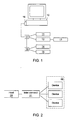
- Fig. 1 is a block diagram illustrating the physical configuration of a plurality of USB peripheral devices attached to a computer system.
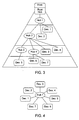
- Fig. 2 is a block diagram illustrating the primary physical components of a USB system.
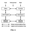
- Fig. 3 is a block diagram illustrating the tiered star physical configuration of a plurality of devices connected to hubs on a USB interconnect.
- Fig. 4 is a block diagram illustrating the simple star logical configuration of a plurality of devices connected to a USB interconnect.
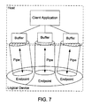
- Fig. 5 is a functional block diagram illustrating the logical and physical flows of data within a USB system.
- Fig. 6 is a functional block diagram illustrating the logical and physical flows of data within the host in a USB system.
- Fig. 7 is a diagram illustrating the flow of data between client software in the USB host and a plurality of endpoints in a USB device.
- Fig. 8 is a diagram illustrating the structure of the USB test application in one embodiment of the invention.
- a host computer utilizes a USB system.
- the USB system includes a USB, a USB host controller coupled to the USB, a host controller driver for driving the host controller and a set of USB interfaces which allow communications between a test application and the host controller driver.
- the test application comprises a USB interpreter which is used to selectively test the functions of the USB system. Specifically, the application is configured to examine standard device descriptors, query USB devices using standard device requests and exercise individual USB interface functions.
- the USB interpreter allows the user to take these actions without having to first create and compile a test application.
- the USB interpreter thereby allows a user to selectively obtain information which facilitates debugging of USB devices and related software.
- USB was motivated primarily by three considerations.
- the USB is a bus designed to provide a simple and efficient method for connecting external peripheral devices to desktop computer systems.
- the figure shows a computer system 10 connected to several peripheral devices 11-15.
- the devices are connected to the USB port 16 on the computer system via hubs 17-18.
- hubs 17-18 on the USB enables users to expand the number of devices which can be connected to the computer system (as compared to the two or three which could be directly connected to a non-USB system.)
- the system may also include compound devices 12 which serve as both hubs and functional devices. (Note that device 13 is connected to the USB via compound device 12.)
- USB host is the computer system which incorporates the USB root hub and forms the basis of the USB system.
- USB devices comprise the peripherals and functional devices Which are to be connected to the computer system.
- USB “devices” may also refer to the hubs which can be connected to the USB to provide additional attachment ports.
- the third part, the USB interconnect comprises the physical connections between the USB devices and the USB host as well as the manner in which the devices communicate with host.
- the host is the computer system in which the USB system is implemented.
- the host incorporates a root hub of the USB which provides one or more attachment points for devices or other hubs.
- a host controller provides the interface between the host and the USB.
- the host controller may be implemented in one or a combination of hardware, firmware and software.
- the USB devices are functional devices which provide capabilities to the system (e.g., an ISDN modem, a joystick or a set of speakers.)
- the USB devices may also be hubs which provide additional attachment points to the USB to which additional devices may be connected. (Non-hub devices are sometimes referred to as functions.)
- Some USB devices serve as both functional devices and hubs to which other devices can be attached.
- the USB Specification requires that all USB devices conform to certain interface standards and thereby ensures that the devices comprehend the USB protocol and respond to standard USB requests and commands.
- the physical aspects of the USB interconnect are defined by the bus topology. (Although the bus topology includes non-physical aspects of the USB interconnect, they will be addressed elsewhere in this disclosure.)
- the bus topology describes the manner in which the USB connects USB devices with the USB host.
- the physical configuration of the USB interconnect is that of a tiered star.
- the host has a root hub which forms the basis of the interconnect Devices and/or additional hubs can be connected to the root and other hubs to form successive tiers of the interconnect.
- each hub forms the center of one of the stars in the tiered star configuration.
- Each wire segment in the interconnect is a point-to-point connection between the host or a hub and another hub or a device.
- USB systems support "hot plugging”. That is, USB devices may be attached to or removed from the USB at any time.
- the USB is designed to detect these changes in its physical topology and accommodate the changes in the available functions. All USB devices are connected to the USB at one of the hubs (either the root hub or one of the hubs chained from the root.) Attachment or removal of a device at a hub is indicated in the hub's port status.
- the hub sends a notification to the host
- the host then sends a query to the hub to determine the reason the notification was sent to the host
- the hub sends the number of the port to which the device was attached to the host
- the host then enables this port and begins communicating with the device via the control pipe (0 endpoint)
- the host determines whether the attached device is a hub or a function and assigns a unique USB address to the device.
- the unique USB address and the 0 endpoint of the device are used as a control pipe for the device. If the newly attached device is a hub which already has devices attached to its ports, this same process is repeated for each of the attached devices. After a device has been attached and communications established between the device and the host, notifications are sent to interested host software.
- the hub disables the port to which the device had been attached and sends notification of the device's removal to the host The host then removes the device and related data from any affected data structures. If the removed device is a hub to which other devices are attached, the removal process is repeated for each of the devices attached to the removed hub. Notifications are sent to interested host software indicating that the removed devices are no longer available.
- the logical topology of the system is a simple star as shown in Fig. 4.
- the logical configuration can be considered a series of direct connections between the individual USB devices and a client software application on the host
- the logical relationship of the client software to the devices can also be thought of as one or more direct connections between the client software and the specific functions provided by the devices. While the view of the logical configuration as being a series of direct connections holds true for most operations, the system remains aware of the tiered physical topology so that devices downstream from a removed hub can be removed from the logical configuration when the hub is removed (see the discussion of hot-swapping above.)
- the USB provides means for communications between client software running on the host and functions provided by the USB devices.
- Figs. 5 and 6 illustrate the flow of data which is communicated between the client software and the device functions.
- the figures show the host as comprising three components: the client software; the USB system software (including USB driver, host controller driver and host of software); and the USB host controller.
- the host controller driver interfaces the host controller with the USB system software
- the USB driver interfaces the USB system software with the client software.
- Fig. 5 shows that the USB device also comprises three components: the function; the logical device; and the USB bus interface.
- a USB logical device is viewed by the USB system as an interface formed by a collection of endpoints.
- An endpoint is a uniquely identifiable portion of a USB device that forms the end of a communications path from the host to the device.
- Software may only communicate with a USB device via its endpoints. (The communications flow is illustrated in the figure by the arrows.)
- the number of each endpoint is determined by the designer of the device. The combination of a device address (assigned by the system at device attachment time) and the endpoint number allows each endpoint to be uniquely identified.
- USB devices are required to have an endpoint with number 0. This endpoint is used to initialize and manipulate (e.g., to configure) the logical device. Endpoint 0 provides access to the device's configuration information and allows access to the device for status and control purposes. Devices can have additional endpoints as required to implement their functions. Devices can have up to 16 additional input endpoints and 16 additional output endpoints (unless they are not full-speed devices, in which case they are limited to a reduced number of endpoints.).
- the communications path between an endpoint on a device and software on the host is referred to as a pipe.
- a pipe comes into existence when a USB device is configured.
- Software clients normally request data transfers via I/O Request Packets (IRPs) to a pipe. The software clients then either wait or are notified when the requests are completed.
- Endpoint 0 has an associated pipe called the Default Pipe.
- the Default Pipe is used by system software to determine device identification and configuration requirements and to configure the device.
- the Default Pipe can also be used by device specific software after the device is configured, but the USB system software retains "ownership" of the Default Pipe and controls its use by client software.
- the client software in this embodiment comprises a test application 30 and a test application driver 31.
- the USB system software 32 comprises USB driver 33 and host control driver 34.
- the USB driver 33 and host cool driver 34 are part of the USB Framework Support.
- the USB Framework Support is a Solaris based implementation of the USB system software and includes a set of interfaces (USB Architecture Interfaces, or USBAI) which allow third party vendors to write USB client drivers on a Solaris SPARC platform.
- Test application 30 includes modules configured to control testing of the different functions of the USB system.
- the separation of the modules capabilities generally conforms to the separation of USB functionalities defined in the USB Specification.
- one module 35 controls the testing of standard device requests defined in Chapter 9 of the Specification, while another module 36 controls testing of hub standard requests as defined in Chapter 11 and another module 38 controls the testing of USBAI functions.
- Interpreter module 37 does not provide for the testing of a separate set of functions, but instead supports testing of all of the USB functions. These modules are all operatively coupled to the body 39 of the test application.
- Test application driver 31 is similarly structured, having a main driver component 40 and several modules 41-44 which correspond to the modules of application 30.
- Test application driver 31 is a loadable driver. That is, when a USB device is hot-plugged, the USB architecture framework will load the driver and create a device node for the newly installed device. If the device is hot-unplugged, the driver will be unloaded as to the unplugged device.
- the test application may be run on any USB device after it is installed.
- the application which is controlled primarily by the interpreter module, takes a device node as an argument, opens the device node and constructs state information for the device based on descriptor information obtained from the device.
- Test application driver 31 maintains the device state for use in testing the device. System test resources are allocated based on the constructed state information. The state information is also used as the basis of test requests which may be formulated by application 30.
- the test requests are forwarded to USBI module 43 of the test application driver 31, which decodes and validates the test parameters. If the test parameters are valid (i.e., within the allowable limits of the parameters,) the test application 30 and application driver 31 construct test cases using USBAI functions.
- Test application driver 31 updates the state information for the device when the function calls are issued and notifies test application 30 of the pass/fail status of the tests after the test functions are performed. Test application 30 then notifies the user.
- the test application runs a suite of tests to verify all of the USBAI function calls.
- the application opens a device node, constructs state information for the device and allocates system resources based on the state information.
- the USBAI module 38 of the test application 30 formulates test requests and parameters based on the state information and conveys the test requests and parameters to the USBAI module 42 of the test application driver 31 for validation.
- the USBAI module of the test application driver formulates a series of test cases using the USBAI functions.
- the USBAI module of the test application driver then makes USBAI function calls corresponding to the test cases to the USB system software.
- the USBAI module of the test application driver returns a pass or fail indication to the test application after analyzing the results of the function calls. This same process is repeated for all of the endpoints in the selected USB device.
- the test application may spawn multiple threads to allow concurrent testing of the different endpoints. Some embodiments may also provide for concurrent testing of multiple USB devices.
- the test application may run a suite of tests to verify that a USB device can provide appropriate device information in response to all of the standard device requests defined in the USB Specification.
- the application again opens a device node, constructs state information for the device and allocates system resources based on the state information. All of the standard device requests are packaged in a request structure which is passed to the test application driver.
- the Chapter 9 module 41 of the test application driver 31 validates the commands in the request structure and then conveys the requests to the USB device via the Default Pipe. The information provided by the device in response to the standard device requests is then returned to the test application.
- Different embodiments of the invention may include various features.
- One such feature is a command line mode.
- command line mode a user may input individual commands which are interpreted and executed by the application to test particular functions of the USB system. This can eliminate unnecessary testing which would be performed by a comprehensive suite of tests. Commands may, however, also be set up to execute a series of operations instead of a single operation.
- the command line mode also allows the test application to be used remotely. In other words, the user does not have to be physically present to test the USB system.
- the user may instead establish communications with the test system and enter commands through the communications link. For example, the user may establish a modem connection between a remote computer and the test system and then enter commands via the modem connection.
- the link may utilize any suitable means for communicating, and the foregoing example of a modem-based link is intended to be illustrative rather than limiting.
- the user may also execute commands which are unrelated to the test system (e.g., Unix shell commands) without having to interrupt the test session.
- the time normally required to start and terminate other test systems to perform non-system functions may therefore be avoided.
- the command line mode can be configured to alias the available commands to a unique list to reduce the amount of typing which is required.
- the test system can also be configured to provide online help to facilitate the user's interaction with the system.
- test system is configured with a functional mode in which the system can single-step through a USBAI function. This may be useful when the user needs to examine traffic on the USB. After a USBAI function command is issued, USB traffic may be examined using a logic analyzer as each step of the function is performed. This can be a valuable debugging feature.
- the system is configured to perform device enumeration. That is, when there are multiple USB devices connected to the system, it can list all the connected devices and construct state information such as port number, device type, device class and path for each of the devices. The user can select the device at a particular port for certain tests and then switch to a different port and test the device connected to that port.
- the test system may be configured to make this information available to the user.
- Information such as device descriptors can be displayed in a matrix format to enable the user to make side-by-side comparisons of the characteristics of individual devices. Because bus enumeration is an ongoing activity in the USB system, devices are recognized as they are connected to the USB and the information which is normally obtained on the devices can be displayed alongside information for previously installed devices. Likewise, information corresponding to devices which are removed from the USB system can be removed from the display.
- the commands which can be input to the test system can be grouped into four categories: commands relating to device state information; standard device request commands; USB architecture interface commands; and miscellaneous commands. Although a number of these commands are listed below, this list is not intended to be limiting. It is contemplated that the USB Specification may be amended to add, delete or modify the allowed commands to accommodate the changing functionality of the USB, and the test system may be adapted to include the new commands and functions of the USB.
- the device state information commands are shown in Table 1 along with their corresponding functions.
- Device state information is tracked for the devices enumerated and identified by the test system. When an endpoint of a device is accessed, its state is updated in the test system.
- Status List s port number, device class and device node name for all available devices. (Usually used after the "enumerate” command.)
- Enumerate Probes all available USB device nodes and creates device state information for each of the connected USB devices.
- Device_state Port Used to switch from a port at which one device is attached to another port at which a second device is connected. (The port numbers can be obtained from the "status" command.)
- the standard device requests are defined in Chapter 9 of the USB Specification.
- the standard device requests are shown in Table 2 along with their corresponding functions. All USB devices are required to respond to standard device requests from the host These requests are made via the device's default pipe using control transfers.
- the request and the request's parameters are sent to the device in the setup packet.
- Get_status Used to obtain status for a device, interface or endpoint Device status consists of a remote_wakeup value corresponding to either enable or disable.
- the returned status in the interface field must be zero.
- the returned status of an endpoint can be either stalled or not stalled.
- clear_feature Used to clear or disable two feature selectors: DEVICE_REMOTE_WAKEUP for the device; or ENDPOINT_STALL on a specific endpoint address.
- the endpoint address can be obtained from the "get_descriptor” or “device_state” commands. set_feature Used to set or enable two feature selectors: DEVICE_REMOTE_WAKEUP for the device; or ENDPOINT_STALL on a specific endpoint address.
- the endpoint address can be obtained from the "get_descriptor” or “device_state” commands. set_address Used only by system software. get_descriptor Used to return the descriptors for device, configuration, string or hub descriptors. All devices must provide a device descriptor and at least one configuration descriptor. The command returns the hub descriptor only in the device is in the hub class. set_descriptor USB devices usually do not support this command. The stall condition should be returned.
- the USBAI commands are shown in Table 3 along with their corresponding. functions.
- the USBAI commands are issued to a particular endpoint of a selected device.
- the USBAI functions corresponding to these commands can be executed in single-step mode in order to allow the user to examine traffic on the USB.
- open_pipe Used to open individual endpoints of USB devices.
- the open_pipe command takes an endpoint index as an argument for opening the pipe.
- the endpoint index can be obtained from the "device_state” command.
- the endpoint must be opened before it can be closed.
- the endpoint index can be obtained from the "device_state” command. start_polling This command applies only to an interrupt endpoint.
- the policy allows the system software to change the behavior of the pipe.
- the height must be opened using "open_pipe” before the policy can be set.
- the two policy fields which can be set by the user are pp_max_outstanding_request and pp_periodic_max_transfer_size. get_policy Used to read the pipe policy.
- the pipe must be opened using the "open_pipe” command. before the policy can be read. reset Used to clear and released the associated resources allocated by the software.
- the pipe must be opened using the "open_pipe” command before the pipe can be reset.
- This command is used to verify the usb_pipe_set_private USB architecture interface function.
- get_private Used to obtain private data that was set in the USB client driver.
- the set_private command must be used before the get_private command.
- the get_private command returns an error if the pipe is not been opened or if the set_private command has not been executed.
- reserve Used to reserve a pipe of an endpoint index by calling usb_pipe_reserve in the USBI module of the USB client driver.
- the pipe of the endpoint must be opened before the pipe can be reserved.
- release Used to release a pipe of an endpoint index. This command calls usb_pipe_release.
- the pipe of an endpoint must be opened and reserved before the pipe can be released.
- the pipe must be opened before this command can be used.
- the pipe must be opened before this command can be used.
- the pipe must be opened before this command can be used.
- the pipe must be opened before this command can be used.
- test application provides for the following miscellaneous commands (see Table 4.) help/? Invokes the help utility of the test application. quit / exit Terminates the test application. sizeof Returns data structure size for device, configuration or endpoint descriptors.
Applications Claiming Priority (2)
| Application Number | Priority Date | Filing Date | Title |
|---|---|---|---|
| US09/232,983 US6389560B1 (en) | 1999-01-19 | 1999-01-19 | Universal serial bus interpreter |
| US232983 | 1999-01-19 |
Publications (3)
| Publication Number | Publication Date |
|---|---|
| EP1031931A2 true EP1031931A2 (de) | 2000-08-30 |
| EP1031931A3 EP1031931A3 (de) | 2000-09-06 |
| EP1031931B1 EP1031931B1 (de) | 2004-03-24 |
Family
ID=22875392
Family Applications (1)
| Application Number | Title | Priority Date | Filing Date |
|---|---|---|---|
| EP00300324A Expired - Lifetime EP1031931B1 (de) | 1999-01-19 | 2000-01-18 | "Universal serial bus" Interpreter |
Country Status (5)
| Country | Link |
|---|---|
| US (1) | US6389560B1 (de) |
| EP (1) | EP1031931B1 (de) |
| JP (1) | JP2000215116A (de) |
| AT (1) | ATE262701T1 (de) |
| DE (1) | DE60009185T2 (de) |
Cited By (5)
| Publication number | Priority date | Publication date | Assignee | Title |
|---|---|---|---|---|
| EP1220102A1 (de) * | 2000-12-29 | 2002-07-03 | Gateway, Inc. | USB-Knotenpunkt mit Weichselektion von Ports |
| US7043587B2 (en) | 2001-09-20 | 2006-05-09 | Lenovo (Singapore) Pte. Ltd. | System and method for connecting a universal serial bus device to a host computer system |
| US7131035B2 (en) | 2002-07-31 | 2006-10-31 | Advanced Micro Devices, Inc. | Serial bus host controller diagnosis |
| EP2293194A1 (de) * | 2009-09-04 | 2011-03-09 | ST-Ericsson (Grenoble) SAS | Vorrcihtung und Verfahren zum Testen einer USB OTG-Hardwareschnittstelle |
| FR2997775A1 (fr) * | 2012-11-06 | 2014-05-09 | Renault Sa | Dispositif et procede d'evaluation de compatibilite d'un systeme electronique avec plusieurs appareils |
Families Citing this family (52)
| Publication number | Priority date | Publication date | Assignee | Title |
|---|---|---|---|---|
| US6343260B1 (en) | 1999-01-19 | 2002-01-29 | Sun Microsystems, Inc. | Universal serial bus test system |
| US6654913B1 (en) * | 1999-02-17 | 2003-11-25 | International Business Machines Corporation | Alternate port apparatus for manufacturing test of integrated serial bus and method therefor |
| US6934774B1 (en) * | 1999-12-20 | 2005-08-23 | Fujitsu Limited | Method and system for reliable device configuration in a computer system |
| US6546450B1 (en) * | 1999-12-22 | 2003-04-08 | Intel Corporation | Method and apparatus for sharing a universal serial bus device among multiple computers by switching |
| US6813725B1 (en) * | 2000-01-26 | 2004-11-02 | Hewlett-Packard Development Company, L.P. | Method for restoring an operating system utilizing a storage device on a USB bus |
| US6484219B1 (en) * | 2000-02-04 | 2002-11-19 | Microsoft Corporation | Host-specified USB device requests |
| US6829726B1 (en) * | 2000-03-06 | 2004-12-07 | Pc-Doctor, Inc. | Method and system for testing a universal serial bus within a computing device |
| US6704819B1 (en) * | 2000-04-19 | 2004-03-09 | Microsoft Corporation | Method and apparatus for device sharing and arbitration |
| US6671831B1 (en) * | 2000-06-13 | 2003-12-30 | Cypress Semiconductor Corp. | Fault tolerant USB method and apparatus |
| US6625761B1 (en) * | 2000-06-13 | 2003-09-23 | Cypress Semiconductor Corp. | Fault tolerant USB method and apparatus |
| US6640312B1 (en) * | 2000-08-01 | 2003-10-28 | National Instruments Corporation | System and method for handling device retry requests on a communication medium |
| US6832273B2 (en) * | 2000-12-21 | 2004-12-14 | Microsoft Corporation | System and method to specify extended configuration descriptor information in USB devices |
| US7127678B2 (en) * | 2000-12-21 | 2006-10-24 | Microsoft Corporation | System and method to specify device specific user interface information in the firmware of a USB device |
| US20020104046A1 (en) * | 2001-01-31 | 2002-08-01 | Mohammad Saleem C. | Method and system for automatically testing a universal serial bus peripheral design |
| US6931575B2 (en) * | 2001-07-27 | 2005-08-16 | Dell Products L.P. | Method and system for testing hardware and software configurations in a computer system |
| US20030056036A1 (en) * | 2001-09-14 | 2003-03-20 | Carlton Gary Don | Apparatus and method for testing universal serial bus communication |
| US6904489B2 (en) * | 2001-10-23 | 2005-06-07 | Digi International Inc. | Methods and systems for remotely accessing universal serial bus devices |
| US6930670B2 (en) * | 2001-12-31 | 2005-08-16 | Aiptek International Inc. | Computer peripheral input system with two input types and method of data communication for the same |
| JP4063593B2 (ja) * | 2002-05-30 | 2008-03-19 | 富士通株式会社 | デバイス情報を管理可能なバスアナライザ |
| US7020801B2 (en) | 2002-06-06 | 2006-03-28 | Microsoft Corporation | Systems and methods for analyzing bus data |
| US7689724B1 (en) | 2002-08-16 | 2010-03-30 | Cypress Semiconductor Corporation | Apparatus, system and method for sharing data from a device between multiple computers |
| US20040044928A1 (en) * | 2002-09-04 | 2004-03-04 | Der-Shyong Chang | Test device and method for information transmission interfaces |
| US7293118B1 (en) | 2002-09-27 | 2007-11-06 | Cypress Semiconductor Corporation | Apparatus and method for dynamically providing hub or host operations |
| US7284149B1 (en) | 2002-10-16 | 2007-10-16 | Ken Scott Fisher | Intermittent connection protection for external computer devices |
| US20040090984A1 (en) * | 2002-11-12 | 2004-05-13 | Intel Corporation | Network adapter for remote devices |
| US20040151327A1 (en) * | 2002-12-11 | 2004-08-05 | Ira Marlow | Audio device integration system |
| US8155342B2 (en) | 2002-12-11 | 2012-04-10 | Ira Marlowe | Multimedia device integration system |
| US20070293183A1 (en) * | 2002-12-11 | 2007-12-20 | Ira Marlowe | Multimedia device integration system |
| US20050239434A1 (en) * | 2002-12-11 | 2005-10-27 | Marlowe Ira M | Multimedia device integration system |
| US7489786B2 (en) * | 2002-12-11 | 2009-02-10 | Ira Marlowe | Audio device integration system |
| US6950859B1 (en) * | 2002-12-23 | 2005-09-27 | Microtune (San Diego), Inc. | Wireless cable replacement for computer peripherals |
| US7136904B2 (en) * | 2002-12-23 | 2006-11-14 | Microtine (San Diego), Inc. | Wireless cable replacement for computer peripherals using a master adapter |
| US7136993B2 (en) * | 2003-04-29 | 2006-11-14 | Dell Products L.P. | Method and system for remote or local access to keyboard control in legacy USB mode with a UHCI USB controller |
| KR100498498B1 (ko) | 2003-05-15 | 2005-07-01 | 삼성전자주식회사 | 하드디스크 드라이브의 테스트 방법 및 이에 적합한 기록매체 |
| KR100518572B1 (ko) | 2003-05-15 | 2005-10-04 | 삼성전자주식회사 | 직렬 멀티 포트 통신 방법, 이에 적합한 장치, 이 장치를제어하는 방법, 그리고 이 제어 방법에 적합한 기록 매체 |
| KR100498499B1 (ko) | 2003-05-15 | 2005-07-01 | 삼성전자주식회사 | 하드디스크 드라이브의 테스트 장치 |
| US20050071109A1 (en) * | 2003-09-25 | 2005-03-31 | Defelice Robert J. | Media platform testing |
| EP1692614A2 (de) * | 2003-11-06 | 2006-08-23 | intuwave Limited | Verfahren zur schnellen softwareanwendungsentwicklung für eine drahtlose mobile einrichtung |
| IL159838A0 (en) | 2004-01-13 | 2004-06-20 | Yehuda Binder | Information device |
| US7216265B2 (en) * | 2004-06-15 | 2007-05-08 | International Business Machines Corporation | Software independent watchdogging scheme for monitoring operating system |
| US7653123B1 (en) | 2004-09-24 | 2010-01-26 | Cypress Semiconductor Corporation | Dynamic data rate using multiplicative PN-codes |
| JP2007066126A (ja) * | 2005-09-01 | 2007-03-15 | Hitachi Global Storage Technologies Netherlands Bv | データ記憶装置のテスト方法及びデータ記憶装置の製造方法 |
| US7526590B2 (en) * | 2006-03-31 | 2009-04-28 | Intel Corporation | Systems and methods for remote pipe resource management in wireless adapters |
| BRPI0621864A2 (pt) * | 2006-07-13 | 2011-12-20 | Trek 2000 Int Ltd | dispositivo portátil com interface do usuário |
| KR100849223B1 (ko) * | 2006-07-27 | 2008-07-31 | 삼성전자주식회사 | Usb 장치 테스트 방법 및 그 시스템 |
| US8473664B2 (en) * | 2006-12-11 | 2013-06-25 | Intel Corporation | Safe removal of external device from computing device |
| US8578179B2 (en) * | 2007-10-19 | 2013-11-05 | Samsung Electronics Co., Ltd | Safe command execution and error recovery for storage devices |
| KR20090128814A (ko) * | 2008-06-11 | 2009-12-16 | 삼성전자주식회사 | 포트 선택기, 이를 이용한 디바이스 평가 시스템 및 방법 |
| US8151017B2 (en) * | 2010-08-23 | 2012-04-03 | Smartech World Wide Limited | Multiplexing application and debug channels on a single USB connection |
| US8566934B2 (en) | 2011-01-21 | 2013-10-22 | Gigavation, Inc. | Apparatus and method for enhancing security of data on a host computing device and a peripheral device |
| KR102039113B1 (ko) | 2011-08-10 | 2019-10-31 | 기타 스리바스타바 | 호스트 컴퓨팅 디바이스와 주변기기의 데이터의 보안을 강화하기 위한 장치 및 방법 |
| TWI525444B (zh) * | 2013-11-28 | 2016-03-11 | 緯創資通股份有限公司 | 電子裝置及隨插即用裝置 |
Family Cites Families (15)
| Publication number | Priority date | Publication date | Assignee | Title |
|---|---|---|---|---|
| US5859993A (en) * | 1996-08-30 | 1999-01-12 | Cypress Semiconductor Corporation | Dual ROM microprogrammable microprocessor and universal serial bus microcontroller development system |
| JPH10207804A (ja) | 1997-01-16 | 1998-08-07 | Alps Electric Co Ltd | 偽装端末システムおよび偽装端末装置 |
| US6219736B1 (en) * | 1997-04-24 | 2001-04-17 | Edwin E. Klingman | Universal serial bus (USB) RAM architecture for use with microcomputers via an interface optimized for integrated services device network (ISDN) |
| US6012103A (en) | 1997-07-02 | 2000-01-04 | Cypress Semiconductor Corp. | Bus interface system and method |
| US5974486A (en) * | 1997-08-12 | 1999-10-26 | Atmel Corporation | Universal serial bus device controller comprising a FIFO associated with a plurality of endpoints and a memory for storing an identifier of a current endpoint |
| US6000042A (en) | 1997-08-25 | 1999-12-07 | 3Com Corporation | Fault detection on a dual supply system for a universal serial bus system |
| JPH1187597A (ja) * | 1997-09-10 | 1999-03-30 | Japan Aviation Electron Ind Ltd | 表面実装用電気部品 |
| US6157975A (en) * | 1998-01-07 | 2000-12-05 | National Semiconductor Corporation | Apparatus and method for providing an interface to a compound Universal Serial Bus controller |
| US6044428A (en) * | 1998-03-17 | 2000-03-28 | Fairchild Semiconductor Corporation | Configurable universal serial bus node |
| US6119194A (en) | 1998-03-19 | 2000-09-12 | Advanced Micro Devices, Inc. | Method and apparatus for monitoring universal serial bus activity |
| US6185569B1 (en) | 1998-06-29 | 2001-02-06 | Microsoft Corporation | Linked data structure integrity verification system which verifies actual node information with expected node information stored in a table |
| TW410516B (en) * | 1998-07-28 | 2000-11-01 | Novatek Microelectronics Corp | Electromagnetic safety enhancement device for universal serial bus and method thereof |
| US6178514B1 (en) | 1998-07-31 | 2001-01-23 | Bradley C. Wood | Method and apparatus for connecting a device to a bus carrying power and a signal |
| US6105097A (en) | 1998-10-14 | 2000-08-15 | Cypress Semiconductor Corp. | Device and method for interconnecting universal serial buses including power management |
| US6202103B1 (en) * | 1998-11-23 | 2001-03-13 | 3A International, Inc. | Bus data analyzer including a modular bus interface |
-
1999
- 1999-01-19 US US09/232,983 patent/US6389560B1/en not_active Expired - Lifetime
-
2000
- 2000-01-18 EP EP00300324A patent/EP1031931B1/de not_active Expired - Lifetime
- 2000-01-18 AT AT00300324T patent/ATE262701T1/de not_active IP Right Cessation
- 2000-01-18 DE DE60009185T patent/DE60009185T2/de not_active Expired - Fee Related
- 2000-01-19 JP JP10965A patent/JP2000215116A/ja active Pending
Non-Patent Citations (4)
| Title |
|---|
| "Revision 1.0" UNIVERSAL SERIAL BUS SPECIFICATION, [Online] 15 January 1996 (1996-01-15), XP002142038 Retrieved from the Internet: <URL:http://www.adelaide.edu.au/~gturner/s pecification/usb/usb-10.pdf> [retrieved on 2000-07-07] * |
| ADAMS M ET AL: "CONFORMANCE TESTING OF VMEBUS AND MULTIBUS II PRODUCTS" IEEE MICRO,US,IEEE INC. NEW YORK, vol. 12, no. 1, 1 February 1992 (1992-02-01), pages 57-64, XP000257468 ISSN: 0272-1732 * |
| DREITLEIN M: "THE CHALLENGE OF TESTING SCSI PERIPHERALS" ELECTRONICS TEST,US,MILLER FREEMAN, SAN FRANCISCO, vol. 13, no. 6, 1 June 1990 (1990-06-01), page 55,56,58,59 XP000174601 ISSN: 0164-9620 * |
| ZELMS C M: "ON-LINE DIAGNOSIS OF PERIPHERALS IN A MINICOMPUTER SYSTEM" PROCEEDINGS OF THE NATIONAL ELECTRONICS CONFERENCE, 1 October 1980 (1980-10-01), XP000748284 * |
Cited By (8)
| Publication number | Priority date | Publication date | Assignee | Title |
|---|---|---|---|---|
| EP1220102A1 (de) * | 2000-12-29 | 2002-07-03 | Gateway, Inc. | USB-Knotenpunkt mit Weichselektion von Ports |
| US6718423B2 (en) | 2000-12-29 | 2004-04-06 | Gateway, Inc. | Bus hub with a selectable number of ports |
| US7043587B2 (en) | 2001-09-20 | 2006-05-09 | Lenovo (Singapore) Pte. Ltd. | System and method for connecting a universal serial bus device to a host computer system |
| US7131035B2 (en) | 2002-07-31 | 2006-10-31 | Advanced Micro Devices, Inc. | Serial bus host controller diagnosis |
| DE10234991B4 (de) * | 2002-07-31 | 2008-07-31 | Advanced Micro Devices, Inc., Sunnyvale | Hostcontrollerdiagnose für einen seriellen Bus |
| EP2293194A1 (de) * | 2009-09-04 | 2011-03-09 | ST-Ericsson (Grenoble) SAS | Vorrcihtung und Verfahren zum Testen einer USB OTG-Hardwareschnittstelle |
| WO2011026851A1 (en) * | 2009-09-04 | 2011-03-10 | St-Ericsson (Grenoble) Sas | Method and apparatus for testing an usb otg hardware interface |
| FR2997775A1 (fr) * | 2012-11-06 | 2014-05-09 | Renault Sa | Dispositif et procede d'evaluation de compatibilite d'un systeme electronique avec plusieurs appareils |
Also Published As
| Publication number | Publication date |
|---|---|
| US6389560B1 (en) | 2002-05-14 |
| EP1031931B1 (de) | 2004-03-24 |
| JP2000215116A (ja) | 2000-08-04 |
| ATE262701T1 (de) | 2004-04-15 |
| DE60009185D1 (de) | 2004-04-29 |
| DE60009185T2 (de) | 2005-01-27 |
| EP1031931A3 (de) | 2000-09-06 |
Similar Documents
| Publication | Publication Date | Title |
|---|---|---|
| US6389560B1 (en) | Universal serial bus interpreter | |
| US6480801B2 (en) | Universal serial bus test system | |
| US6970957B1 (en) | Dynamically configuring resources for cycle translation in a computer system | |
| US8725914B2 (en) | Message signaled interrupt management for a computer input/output fabric incorporating platform independent interrupt manager | |
| US6141708A (en) | Host bridge configured to mask a portion of peripheral devices coupled to a bus further downstream of the host bridge from a host processor | |
| US8386654B2 (en) | System and method for transforming PCIe SR-IOV functions to appear as legacy functions | |
| US6272584B1 (en) | System board with consolidated EEPROM module | |
| JP3974288B2 (ja) | 周辺装置をコンピュータに登録する方法及び装置 | |
| EP1252569B1 (de) | Virtuelles rom für geräte-aufzählung | |
| JP2004531838A (ja) | 仮想pciデバイス装置及び方法 | |
| US8725919B1 (en) | Device configuration for multiprocessor systems | |
| US6546482B1 (en) | Invalid configuration detection resource | |
| US8775712B2 (en) | Bus connecting device for connecting host with external device | |
| US6216196B1 (en) | System and method for multiple device drivers to arbitrate for a single device | |
| US5991826A (en) | System for configuring computer devices according to configuration patterns | |
| JP2503183B2 (ja) | バス・アダプタ・システム | |
| CN112084128B (zh) | 消息中断通信方法、计算机设备和存储介质 | |
| US5964871A (en) | Resolution of resource conflicts by reduction of systems to solve | |
| US8527745B2 (en) | Input/output device including a host interface for processing function level reset requests and updating a timer value corresponding to a time until application hardware registers associated with the function level reset requests are available | |
| US20110087820A1 (en) | Queue sharing and reconfiguration in pci express links | |
| US7110928B1 (en) | Apparatuses and methods for modeling shared bus systems | |
| Bandara et al. | Enabling VirtIO Driver Support on FPGAs | |
| Wong | PCI express multi-root switch reconfiguration during system operation | |
| JP2001056793A (ja) | 情報処理装置 | |
| Devices | QNX® Neutrino® Device Drivers |
Legal Events
| Date | Code | Title | Description |
|---|---|---|---|
| PUAI | Public reference made under article 153(3) epc to a published international application that has entered the european phase |
Free format text: ORIGINAL CODE: 0009012 |
|
| PUAL | Search report despatched |
Free format text: ORIGINAL CODE: 0009013 |
|
| AK | Designated contracting states |
Kind code of ref document: A2 Designated state(s): AT BE CH CY DE DK ES FI FR GB GR IE IT LI LU MC NL PT SE |
|
| AX | Request for extension of the european patent |
Free format text: AL;LT;LV;MK;RO;SI |
|
| AK | Designated contracting states |
Kind code of ref document: A3 Designated state(s): AT BE CH CY DE DK ES FI FR GB GR IE IT LI LU MC NL PT SE |
|
| AX | Request for extension of the european patent |
Free format text: AL;LT;LV;MK;RO;SI |
|
| 17P | Request for examination filed |
Effective date: 20010214 |
|
| AKX | Designation fees paid |
Free format text: AT BE CH CY DE DK ES FI FR GB GR IE IT LI LU MC NL PT SE |
|
| 17Q | First examination report despatched |
Effective date: 20020613 |
|
| RAP1 | Party data changed (applicant data changed or rights of an application transferred) |
Owner name: SUN MICROSYSTEMS, INC. |
|
| GRAP | Despatch of communication of intention to grant a patent |
Free format text: ORIGINAL CODE: EPIDOSNIGR1 |
|
| GRAS | Grant fee paid |
Free format text: ORIGINAL CODE: EPIDOSNIGR3 |
|
| GRAA | (expected) grant |
Free format text: ORIGINAL CODE: 0009210 |
|
| AK | Designated contracting states |
Kind code of ref document: B1 Designated state(s): AT BE CH CY DE DK ES FI FR GB GR IE IT LI LU MC NL PT SE |
|
| PG25 | Lapsed in a contracting state [announced via postgrant information from national office to epo] |
Ref country code: IT Free format text: LAPSE BECAUSE OF FAILURE TO SUBMIT A TRANSLATION OF THE DESCRIPTION OR TO PAY THE FEE WITHIN THE PRE;WARNING: LAPSES OF ITALIAN PATENTS WITH EFFECTIVE DATE BEFORE 2007 MAY HAVE OCCURRED AT ANY TIME BEFORE 2007. THE CORRECT EFFECTIVE DATE MAY BE DIFFERENT FROM THE ONE RECORDED.SCRIBED TIME-LIMIT Effective date: 20040324 Ref country code: AT Free format text: LAPSE BECAUSE OF FAILURE TO SUBMIT A TRANSLATION OF THE DESCRIPTION OR TO PAY THE FEE WITHIN THE PRESCRIBED TIME-LIMIT Effective date: 20040324 Ref country code: NL Free format text: LAPSE BECAUSE OF FAILURE TO SUBMIT A TRANSLATION OF THE DESCRIPTION OR TO PAY THE FEE WITHIN THE PRESCRIBED TIME-LIMIT Effective date: 20040324 Ref country code: LI Free format text: LAPSE BECAUSE OF FAILURE TO SUBMIT A TRANSLATION OF THE DESCRIPTION OR TO PAY THE FEE WITHIN THE PRESCRIBED TIME-LIMIT Effective date: 20040324 Ref country code: FI Free format text: LAPSE BECAUSE OF FAILURE TO SUBMIT A TRANSLATION OF THE DESCRIPTION OR TO PAY THE FEE WITHIN THE PRESCRIBED TIME-LIMIT Effective date: 20040324 Ref country code: CH Free format text: LAPSE BECAUSE OF FAILURE TO SUBMIT A TRANSLATION OF THE DESCRIPTION OR TO PAY THE FEE WITHIN THE PRESCRIBED TIME-LIMIT Effective date: 20040324 Ref country code: BE Free format text: LAPSE BECAUSE OF FAILURE TO SUBMIT A TRANSLATION OF THE DESCRIPTION OR TO PAY THE FEE WITHIN THE PRESCRIBED TIME-LIMIT Effective date: 20040324 |
|
| REG | Reference to a national code |
Ref country code: GB Ref legal event code: FG4D |
|
| REG | Reference to a national code |
Ref country code: CH Ref legal event code: EP |
|
| REG | Reference to a national code |
Ref country code: IE Ref legal event code: FG4D |
|
| REF | Corresponds to: |
Ref document number: 60009185 Country of ref document: DE Date of ref document: 20040429 Kind code of ref document: P |
|
| PG25 | Lapsed in a contracting state [announced via postgrant information from national office to epo] |
Ref country code: SE Free format text: LAPSE BECAUSE OF FAILURE TO SUBMIT A TRANSLATION OF THE DESCRIPTION OR TO PAY THE FEE WITHIN THE PRESCRIBED TIME-LIMIT Effective date: 20040624 Ref country code: GR Free format text: LAPSE BECAUSE OF FAILURE TO SUBMIT A TRANSLATION OF THE DESCRIPTION OR TO PAY THE FEE WITHIN THE PRESCRIBED TIME-LIMIT Effective date: 20040624 Ref country code: DK Free format text: LAPSE BECAUSE OF FAILURE TO SUBMIT A TRANSLATION OF THE DESCRIPTION OR TO PAY THE FEE WITHIN THE PRESCRIBED TIME-LIMIT Effective date: 20040624 |
|
| PG25 | Lapsed in a contracting state [announced via postgrant information from national office to epo] |
Ref country code: ES Free format text: LAPSE BECAUSE OF FAILURE TO SUBMIT A TRANSLATION OF THE DESCRIPTION OR TO PAY THE FEE WITHIN THE PRESCRIBED TIME-LIMIT Effective date: 20040705 |
|
| NLV1 | Nl: lapsed or annulled due to failure to fulfill the requirements of art. 29p and 29m of the patents act | ||
| REG | Reference to a national code |
Ref country code: CH Ref legal event code: PL |
|
| ET | Fr: translation filed | ||
| PG25 | Lapsed in a contracting state [announced via postgrant information from national office to epo] |
Ref country code: GB Free format text: LAPSE BECAUSE OF NON-PAYMENT OF DUE FEES Effective date: 20050118 Ref country code: LU Free format text: LAPSE BECAUSE OF NON-PAYMENT OF DUE FEES Effective date: 20050118 Ref country code: CY Free format text: LAPSE BECAUSE OF FAILURE TO SUBMIT A TRANSLATION OF THE DESCRIPTION OR TO PAY THE FEE WITHIN THE PRESCRIBED TIME-LIMIT Effective date: 20050118 Ref country code: IE Free format text: LAPSE BECAUSE OF NON-PAYMENT OF DUE FEES Effective date: 20050118 |
|
| PLBE | No opposition filed within time limit |
Free format text: ORIGINAL CODE: 0009261 |
|
| STAA | Information on the status of an ep patent application or granted ep patent |
Free format text: STATUS: NO OPPOSITION FILED WITHIN TIME LIMIT |
|
| PG25 | Lapsed in a contracting state [announced via postgrant information from national office to epo] |
Ref country code: MC Free format text: LAPSE BECAUSE OF NON-PAYMENT OF DUE FEES Effective date: 20050131 |
|
| 26N | No opposition filed |
Effective date: 20041228 |
|
| PG25 | Lapsed in a contracting state [announced via postgrant information from national office to epo] |
Ref country code: DE Free format text: LAPSE BECAUSE OF NON-PAYMENT OF DUE FEES Effective date: 20050802 |
|
| GBPC | Gb: european patent ceased through non-payment of renewal fee |
Effective date: 20050118 |
|
| PG25 | Lapsed in a contracting state [announced via postgrant information from national office to epo] |
Ref country code: FR Free format text: LAPSE BECAUSE OF NON-PAYMENT OF DUE FEES Effective date: 20050930 |
|
| REG | Reference to a national code |
Ref country code: IE Ref legal event code: MM4A |
|
| REG | Reference to a national code |
Ref country code: FR Ref legal event code: ST |
|
| PG25 | Lapsed in a contracting state [announced via postgrant information from national office to epo] |
Ref country code: PT Free format text: LAPSE BECAUSE OF NON-PAYMENT OF DUE FEES Effective date: 20040824 |