EP1031911A1 - Data processing apparatus with detachable keyboard - Google Patents
Data processing apparatus with detachable keyboard Download PDFInfo
- Publication number
- EP1031911A1 EP1031911A1 EP00301366A EP00301366A EP1031911A1 EP 1031911 A1 EP1031911 A1 EP 1031911A1 EP 00301366 A EP00301366 A EP 00301366A EP 00301366 A EP00301366 A EP 00301366A EP 1031911 A1 EP1031911 A1 EP 1031911A1
- Authority
- EP
- European Patent Office
- Prior art keywords
- key input
- body portion
- support
- processing apparatus
- data processing
- Prior art date
- Legal status (The legal status is an assumption and is not a legal conclusion. Google has not performed a legal analysis and makes no representation as to the accuracy of the status listed.)
- Withdrawn
Links
Images



Classifications
-
- G—PHYSICS
- G06—COMPUTING OR CALCULATING; COUNTING
- G06F—ELECTRIC DIGITAL DATA PROCESSING
- G06F1/00—Details not covered by groups G06F3/00 - G06F13/00 and G06F21/00
- G06F1/16—Constructional details or arrangements
- G06F1/1613—Constructional details or arrangements for portable computers
- G06F1/1633—Constructional details or arrangements of portable computers not specific to the type of enclosures covered by groups G06F1/1615 - G06F1/1626
- G06F1/1684—Constructional details or arrangements related to integrated I/O peripherals not covered by groups G06F1/1635 - G06F1/1675
- G06F1/1698—Constructional details or arrangements related to integrated I/O peripherals not covered by groups G06F1/1635 - G06F1/1675 the I/O peripheral being a sending/receiving arrangement to establish a cordless communication link, e.g. radio or infrared link, integrated cellular phone
-
- G—PHYSICS
- G06—COMPUTING OR CALCULATING; COUNTING
- G06F—ELECTRIC DIGITAL DATA PROCESSING
- G06F1/00—Details not covered by groups G06F3/00 - G06F13/00 and G06F21/00
- G06F1/16—Constructional details or arrangements
- G06F1/1613—Constructional details or arrangements for portable computers
- G06F1/1615—Constructional details or arrangements for portable computers with several enclosures having relative motions, each enclosure supporting at least one I/O or computing function
- G06F1/1616—Constructional details or arrangements for portable computers with several enclosures having relative motions, each enclosure supporting at least one I/O or computing function with folding flat displays, e.g. laptop computers or notebooks having a clamshell configuration, with body parts pivoting to an open position around an axis parallel to the plane they define in closed position
-
- G—PHYSICS
- G06—COMPUTING OR CALCULATING; COUNTING
- G06F—ELECTRIC DIGITAL DATA PROCESSING
- G06F1/00—Details not covered by groups G06F3/00 - G06F13/00 and G06F21/00
- G06F1/16—Constructional details or arrangements
- G06F1/1613—Constructional details or arrangements for portable computers
- G06F1/1633—Constructional details or arrangements of portable computers not specific to the type of enclosures covered by groups G06F1/1615 - G06F1/1626
- G06F1/1662—Details related to the integrated keyboard
- G06F1/1669—Detachable keyboards
Definitions
- the present invention relates to a data processing apparatus, such as a personal computer or word processor, composed of a body portion having a display panel provided on the front face thereof and a key input portion linked to an end portion of the body portion.
- a type of data processing apparatus is conventionally known that is composed of a body portion incorporating a basic circuit and having a display panel provided on the front face thereof and a key input portion linked to the body portion.
- the size of the key input portion is made substantially identical with that of the body portion, and thus the former becomes larger as the latter becomes larger. This not only spoils the portability of the key input portion but also creates unnecessary space therein.
- the body portion becomes larger, it becomes less stable in the state (3) above and is thus more prone to topple down when subjected to vibrations or a shock.
- An object of the present invention is to provide a data processing apparatus that can be brought into one of the states (1) to (3) described above without requiring any extra support member, without requiring any extra portion to keep or insert such a member in, and thus without requiring a body portion to be made thicker and that nevertheless achieves stable support of the body portion in a simple structure.
- a data processing apparatus is provided with: a body portion incorporating a basic circuit and having a display panel provided on the front face thereof: a support portion rotatably linked to an end portion of the body portion; a key input portion detachably linked to an end portion of the support portion; and communication means for communicating data entered in the key input portion to the body portion on a cordless basis when the key input portion is detached from the support portion.
- a data processing apparatus is provided with: a body portion incorporating a basic circuit and having a display panel provided on the front face thereof; a support portion rotatably linked to an end portion of the body portion; and a key input portion detachably linked to an end portion of the support portion.
- the data processing apparatus can be brought into any one of the following three states: a first state in which the support portion together with the key input portion linked thereto covers the face of the body portion on which the display panel is provided; a second state in which, as compared with the first state, the support portion together with the key input portion linked thereto is placed on a flat surface and the face of the body portion on which the display panel is provided is rotated up so as to face an operator; and a third state in which, as compared with the second state, the key input portion is detached from the support portion and the support portion is rotated backward so as to be placed on the flat surface behind the body portion.
- Fig. 1 is a side view of the appearance of a data processing apparatus embodying the invention, showing its "folded-up" state into which it is brought into when not in use; that is, Fig. 1 shows its first state in which a key input portion and a support portion are linked together and are so located as to cover the display panel face of a body portion.
- reference numeral 100 represents a body portion
- reference numeral 200 represents a support portion
- reference numeral 300 represents a key input portion.
- the data processing apparatus is brought into this state when not in use, in particular when kept in storage or transported.
- a schematic perspective view of the same state is shown in Fig. 4.
- Fig. 2 is a side view of the appearance of the data processing apparatus embodying the invention, showing its "unfolded" state; that is.
- Fig. 2 shows its second state in which, as compared with the first state, the support portion 200 together with the key input portion 300 linked thereto is placed on a flat surface and the body portion 100 is rotated up so as to allow the display panel face to face the operator.
- a schematic perspective view of the same state is shown in Fig. 5.
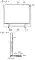
- Figs. 3A and 3B are a front view and a side view, respectively, of the appearance of the data processing apparatus embodying the invention, showing its state in which, as compared with the second state, the key input portion 300 is detached from the support portion 200.
- FIGs. 3A and 3B show the third state of the data processing apparatus in which, as compared with the second state shown in Fig. 2, the support portion 200 is rotated backward to behind the body portion 100 to achieve stable support of the body portion 100 even with the key input portion 300 detached. It is to be noted that, in both of the front and side views Figs. 3A and 3B, the key input portion 300 is omitted. To facilitate the understanding of Figs. 3A and 3B, a schematic perspective view of the same state is shown in Fig. 6.
- the body portion 100 is provided with a display panel 101, a receiver 102, and a body-portion-side hinge 103, and incorporates a basic circuit, for controlling the entire data processing apparatus, composed of a CPU, ROM, RAM, and others.
- the display panel 101 is an LCD (liquid crystal display) panel, and is so arranged as to be exposed on the front face of the body portion 100 and laid over the basic circuit incorporated in the body portion 100.
- LCD liquid crystal display
- the receiver 102 is provided with an infrared communication function that allows the body portion 100 to receive, on a cordless basis, the data entered in the key input portion 300 and transmitted from the transmitter (described later) provided therein. To obtain the optimum communication conditions, it is preferable that this receiver 102 be provided in an upper-end portion of the body portion 100 so that, irrespective of whether the data processing apparatus is in the second state shown in Fig. 5 or in the third state shown in Fig. 6, the cordless communication between the body portion 100 and the key input portion 300 will not be intercepted by the casing of the data processing apparatus or other obstacles.
- the body-portion-side hinge 103 is provided in a lower-end portion of the body portion 100.
- the body-portion-side hinge 103 together with support-portion-side hinges (described later), links the body portion 100 and the support portion 200 together in such a way that the support portion 200 is rotatable from the first state shown in Fig. 4, to the second state shown in Fig. 5, and further to the third state shown in Fig. 6.
- the support portion 200 supports the body portion 100, and is provided with a battery 201 for the body portion 100, a power inlet 202, support-portion-side hinges 203, fitting holes 204 that allow the key input portion 300 to be linked to the support portion 200, and others.
- the battery 201 supplies the body portion 100 with electric power from which the display panel 101, the basic circuit, and others operate.
- the power inlet 202 allows electric power to be fed in from the outside.
- the support-portion-side hinges 203 are provided in an end portion of the support portion 200.
- the fitting holes 204 into which the fitting projections (described later) provided on the key input portion 300 are inserted in the first and second states shown in Figs. 4 and 5, thereby allow the support portion 200 and the key input portion 300 to be linked together.
- the body portion 100 and the support portion 200 are so designed as to allow the body portion 100 to be fixed at a desired angle relative to the support portion 200 in the second and third states shown in Figs. 5 and 6. This is achieved, for example, by securing a certain friction in the linkage between the body-portion-side hinge 103 and the support-portion-side hinges 203.
- the key input portion 300 is provided with a transmitter 301, fitting projections 302, a battery (not shown) for the key input portion 300, input devices such as a key board 311 and a pointing device (i.e. a mouse, tablet, or the like) for entering character-based, graphic, or other data, and others.
- a pointing device i.e. a mouse, tablet, or the like
- the transmitter 301 is provided with an infrared communication function that allows the data entered in the key input portion 300 to be transmitted, on a cordless basis, to the receiver 102 of the body portion 100.
- the fitting projections 302 which are inserted into the fitting holes 204 (see Fig. 3B) provided in the support portion 200 in the first and second states shown in Figs. 4 and 5, thereby allow the support portion 200 and the key input portion 300 to be linked together.
- the body portion 100, the support portion 200, and the key input portion 300 are so sized that the support portion 200 and the key input portion 300, when linked together as in the first state shown in Fig. 4, are approximately as large as the body portion 100.
- the data processing apparatus embodying the invention can be brought into the first state shown in Fig. 4 when it is not in use such as when it is kept in storage or transported.
- this data processing apparatus when this data processing apparatus is used, it can be brought into either the second state shown in Fig. 5 in which the support portion 200 and the key input portion 300 are linked together or into the third state shown in Fig. 6 in which the support portion 200 and the key input portion 300 are detached from each other.
- the body portion 100 can be supported stably in a simple structure that does not require a support member to be attached to the rear face of the body portion 100.
- the body portion 100 and the key input portion 300 exchange the entered data on a cordless basis, and therefore, in the third state shown in Fig. 6, the detached key input portion 300 does not need to be connected to the body portion 100 by way of a cable or the like. This facilitates key input operation.
- the support portion 200 and the key input portion 300 when linked together, are approximately as large as the body portion 100, and therefore, by making the support portion 200 sufficiently large relative to the body portion 100, the body portion 100 can be supported stably so as not to topple down easily when the data processing apparatus is used in the third state shown in Fig. 6.
- the relatively heavy battery 201 for the body portion 100 is provided in the support portion 200. Providing such a heavy member in the support portion 200 helps achieve stable support of the body portion 100 by preventing it from toppling down when subjected to vibrations or a shock.
- Fig. 7 is a block diagram showing an example of the hardware configuration of the data processing apparatus of this embodiment.
- the body portion 100 has a display panel 101, a receiver 102, a CPU 111, a ROM 112, a RAM 113, and display control means 114.
- the CPU 111 controls the entire data processing apparatus by executing a program for controlling the data processing apparatus stored in the ROM 112.
- the ROM 112 is used to store, in addition to the above-mentioned program executed by the CPU 111, the data used thereby and the data related to input/output operation, such as the codes of characters that can be displayed.
- the RAM 113 is used to store temporarily the results of the operation executed by the CPU 111, the entered data received by the receiver 102, and other data.
- the display control means 114 is, for example, a liquid crystal display driving circuit for controlling a liquid crystal display device.
- the display control means 114 serves to control the display on the display panel 101 by controlling, on a hardware basis, the display device on which to achieve display, and thereby permits characters and images entered from the key input portion 300 to be displayed on the display panel 101.
- the support portion 200 has a battery 201 for the body portion 100 and a power inlet 202.
- the battery 201 for the body portion 100 supplies electric power to the body portion 100.
- the power inlet 202 allows electric power to be fed in from the outside and then fed, through the battery 201 or directly, to the body portion 100.
- the key input portion 300 has a transmitter 301, a battery 303 for the key input portion 300, a keyboard 311, a pointing device 312, and input control means 313.
- the input control means 313 controls data entry from the keyboard 311 and the pointing device 312, and feeds the entered data to the transmitter 301.
- an LCD (liquid crystal display) panel is used as the display panel 101; however, it is also possible to use instead a display device of any other type such as a plasma display.
- fitting projections on the support portion 200 and fitting holes in the key input portion 300 may link the support portion 200 and the key input portion 300 together.
- each of the support portion 200 and the key input portion 300 may be linked together in any manner as long as they can be linked together easily and firmly.
- hook slots are provided in the support portion 200 and in the key input portion 300, in appropriate positions thereon that face the portion around the display panel 101 of the body portion 100, and hooks are provided in the portion around the display panel 101 of the body portion 100, in the positions thereon that face those hook slots. These hooks are inserted into the corresponding hook slots so as to be engaged therewith, and this helps prevent the body portion 100 from being unfolded easily.
- hooks on the body portion 100 and hook slots in the support portion 200 and in the key input portion 300 it is also possible to provide hook slots in the body portion and hooks on the support portion 200 and on the key input portion 300 to fix the body portion 100 to the support portion 200 and the key input portion 300 linked together.
- the support portion 200 alone can be rotated so as to cover the display panel face, with the hooks of the body portion 100 engaged with the hook slots of the support portion 200. This helps keep the support portion 200 covering part of the display panel face without rotating into an unfolded position, and thereby prevent the display panel face from being uncovered wholly.
- a key board 311 and a pointing device 312 i.e. a mouse, tablet, or the like
- a tablet integral with a display using a liquid crystal display panel instead of using a key board 311 and a pointing device 312 (i.e. a mouse, tablet, or the like) as input devices in the key input portion 300 to allow entry of character-based, graphic, or other data, it is also possible to use a tablet integral with a display using a liquid crystal display panel.
- the communication portion provided in the body portion 100 and in the key input portion 300 allows exchange of data on a cordless basis irrespective of whether the key input portion 300 is detached from the support portion 200 or not.
- the key input portion 300 is not detached from the support portion 200, it is possible to communicate data either on a direct-link basis or on a cordless basis. This helps enhance data security.
Landscapes
- Engineering & Computer Science (AREA)
- Computer Hardware Design (AREA)
- Theoretical Computer Science (AREA)
- Physics & Mathematics (AREA)
- General Engineering & Computer Science (AREA)
- Human Computer Interaction (AREA)
- General Physics & Mathematics (AREA)
- Mathematical Physics (AREA)
- Input From Keyboards Or The Like (AREA)
- Casings For Electric Apparatus (AREA)
Abstract
A data processing apparatus has a body portion incorporating a basic circuit
and having a display panel provided on the front face thereof, a support portion
rotatably linked to an end portion of the body portion, a key input portion
detachably linked to an end portion of the support portion, and a communication
portion for communicating data entered in the key input portion to the body
portion on a cordless basis when the key input portion is detached from the
support portion.
Description
The present invention relates to a data processing apparatus, such as a
personal computer or word processor, composed of a body portion having a display
panel provided on the front face thereof and a key input portion linked to an end
portion of the body portion.
A type of data processing apparatus is conventionally known that is
composed of a body portion incorporating a basic circuit and having a display
panel provided on the front face thereof and a key input portion linked to the body
portion. Some of this type of data processing apparatus are designed to allow
themselves to be brought into one of the following three states:
A conventional example of a data processing apparatus that can be brought
into one of the states (1) to (3) described above is disclosed in Japanese Laid-Open
Patent Application No. H5-313786.
However, according to Japanese Laid-Open Patent Application No. H5-313786
mentioned above, when the state of the data processing apparatus is
changed from the state (1) above to the state (2) above, and further from the state
(2) above to the state (3) above, to achieve stable support of the body portion even
with the key input portion detached therefrom, it is necessary to insert a support
member into a hole or holes formed in the rear face of the body portion. This not
only demands extra operation steps but also leads easily to loss of the support
member if it drops out.
Moreover, it is necessary to form, in the rear face of the body portion, a
recessed portion in which the support member is kept when retracted and a hole or
holes into which it is inserted. This inevitably increases the thickness of the body
portion and thus spoils the portability and storability thereof.
Moreover, to permit the support member to support the body portion at a
desired angle, it is necessary to design a complicated structure, for example,
having a hole or holes that are so formed as to allow the support member to be
inserted therein at a number of angles.
Furthermore, the size of the key input portion is made substantially
identical with that of the body portion, and thus the former becomes larger as the
latter becomes larger. This not only spoils the portability of the key input portion
but also creates unnecessary space therein.
Moreover, as the body portion becomes larger, it becomes less stable in the
state (3) above and is thus more prone to topple down when subjected to vibrations
or a shock.
An object of the present invention is to provide a data processing apparatus
that can be brought into one of the states (1) to (3) described above without
requiring any extra support member, without requiring any extra portion to keep or
insert such a member in, and thus without requiring a body portion to be made
thicker and that nevertheless achieves stable support of the body portion in a
simple structure.
To achieve the above object, according to one aspect of the present
invention, a data processing apparatus is provided with: a body portion
incorporating a basic circuit and having a display panel provided on the front face
thereof: a support portion rotatably linked to an end portion of the body portion; a
key input portion detachably linked to an end portion of the support portion; and
communication means for communicating data entered in the key input portion to
the body portion on a cordless basis when the key input portion is detached from
the support portion.
According to another aspect of the present invention, a data processing
apparatus is provided with: a body portion incorporating a basic circuit and
having a display panel provided on the front face thereof; a support portion
rotatably linked to an end portion of the body portion; and a key input portion
detachably linked to an end portion of the support portion. Here, the data
processing apparatus can be brought into any one of the following three states: a
first state in which the support portion together with the key input portion linked
thereto covers the face of the body portion on which the display panel is provided;
a second state in which, as compared with the first state, the support portion
together with the key input portion linked thereto is placed on a flat surface and
the face of the body portion on which the display panel is provided is rotated up so
as to face an operator; and a third state in which, as compared with the second
state, the key input portion is detached from the support portion and the support
portion is rotated backward so as to be placed on the flat surface behind the body
portion.
This and other objects and features of the present invention will become
clear from the following description, taken in conjunction with the preferred
embodiments with reference to the accompanying drawings in which:
Hereinafter, a data processing apparatus embodying the present invention
will be described with reference to the accompanying drawings.
Fig. 1 is a side view of the appearance of a data processing apparatus
embodying the invention, showing its "folded-up" state into which it is brought
into when not in use; that is, Fig. 1 shows its first state in which a key input
portion and a support portion are linked together and are so located as to cover the
display panel face of a body portion.
In Fig. 1, reference numeral 100 represents a body portion, reference
numeral 200 represents a support portion, and reference numeral 300 represents a
key input portion. Usually, the data processing apparatus is brought into this
state when not in use, in particular when kept in storage or transported. To
facilitate the understanding of Fig. 1, a schematic perspective view of the same
state is shown in Fig. 4.
Fig. 2 is a side view of the appearance of the data processing apparatus
embodying the invention, showing its "unfolded" state; that is. Fig. 2 shows its
second state in which, as compared with the first state, the support portion 200
together with the key input portion 300 linked thereto is placed on a flat surface
and the body portion 100 is rotated up so as to allow the display panel face to face
the operator. To facilitate the understanding of Fig. 2, a schematic perspective
view of the same state is shown in Fig. 5.
Figs. 3A and 3B are a front view and a side view, respectively, of the
appearance of the data processing apparatus embodying the invention, showing its
state in which, as compared with the second state, the key input portion 300 is
detached from the support portion 200.
That is, Figs. 3A and 3B show the third state of the data processing
apparatus in which, as compared with the second state shown in Fig. 2, the
support portion 200 is rotated backward to behind the body portion 100 to achieve
stable support of the body portion 100 even with the key input portion 300
detached. It is to be noted that, in both of the front and side views Figs. 3A and
3B, the key input portion 300 is omitted. To facilitate the understanding of Figs.
3A and 3B, a schematic perspective view of the same state is shown in Fig. 6.
The body portion 100 is provided with a display panel 101, a receiver 102,
and a body-portion-side hinge 103, and incorporates a basic circuit, for controlling
the entire data processing apparatus, composed of a CPU, ROM, RAM, and others.
The display panel 101 is an LCD (liquid crystal display) panel, and is so
arranged as to be exposed on the front face of the body portion 100 and laid over
the basic circuit incorporated in the body portion 100.
The receiver 102 is provided with an infrared communication function that
allows the body portion 100 to receive, on a cordless basis, the data entered in the
key input portion 300 and transmitted from the transmitter (described later)
provided therein. To obtain the optimum communication conditions, it is
preferable that this receiver 102 be provided in an upper-end portion of the body
portion 100 so that, irrespective of whether the data processing apparatus is in the
second state shown in Fig. 5 or in the third state shown in Fig. 6, the cordless
communication between the body portion 100 and the key input portion 300 will
not be intercepted by the casing of the data processing apparatus or other obstacles.
The body-portion-side hinge 103 is provided in a lower-end portion of the
body portion 100. The body-portion-side hinge 103, together with support-portion-side
hinges (described later), links the body portion 100 and the support
portion 200 together in such a way that the support portion 200 is rotatable from
the first state shown in Fig. 4, to the second state shown in Fig. 5, and further to
the third state shown in Fig. 6.
The support portion 200 supports the body portion 100, and is provided with
a battery 201 for the body portion 100, a power inlet 202, support-portion-side
hinges 203, fitting holes 204 that allow the key input portion 300 to be linked to
the support portion 200, and others.
The battery 201 supplies the body portion 100 with electric power from
which the display panel 101, the basic circuit, and others operate. The power
inlet 202 allows electric power to be fed in from the outside.
The support-portion-side hinges 203 are provided in an end portion of the
support portion 200. The support-portion-side hinges 203, together with the body-portion-side
hinge 103, link the body portion 100 and the support portion 200
together in such a way that the support portion 200 is rotatable from the first state
shown in Fig. 4, to the second state shown in Fig. 5, and further to the third state
shown in Fig. 6.
The fitting holes 204, into which the fitting projections (described later)
provided on the key input portion 300 are inserted in the first and second states
shown in Figs. 4 and 5, thereby allow the support portion 200 and the key input
portion 300 to be linked together.
The body portion 100 and the support portion 200 are so designed as to
allow the body portion 100 to be fixed at a desired angle relative to the support
portion 200 in the second and third states shown in Figs. 5 and 6. This is
achieved, for example, by securing a certain friction in the linkage between the
body-portion-side hinge 103 and the support-portion-side hinges 203.
As shown in Fig. 6, the key input portion 300 is provided with a transmitter
301, fitting projections 302, a battery (not shown) for the key input portion 300,
input devices such as a key board 311 and a pointing device (i.e. a mouse, tablet, or
the like) for entering character-based, graphic, or other data, and others.
The transmitter 301 is provided with an infrared communication function
that allows the data entered in the key input portion 300 to be transmitted, on a
cordless basis, to the receiver 102 of the body portion 100.
The fitting projections 302, which are inserted into the fitting holes 204 (see
Fig. 3B) provided in the support portion 200 in the first and second states shown in
Figs. 4 and 5, thereby allow the support portion 200 and the key input portion 300
to be linked together.
The body portion 100, the support portion 200, and the key input portion
300 are so sized that the support portion 200 and the key input portion 300, when
linked together as in the first state shown in Fig. 4, are approximately as large as
the body portion 100.
Thus, the data processing apparatus embodying the invention can be
brought into the first state shown in Fig. 4 when it is not in use such as when it is
kept in storage or transported. On the other hand, when this data processing
apparatus is used, it can be brought into either the second state shown in Fig. 5 in
which the support portion 200 and the key input portion 300 are linked together or
into the third state shown in Fig. 6 in which the support portion 200 and the key
input portion 300 are detached from each other. In this way, the body portion 100
can be supported stably in a simple structure that does not require a support
member to be attached to the rear face of the body portion 100. Moreover, there is
no need to provide a portion to keep or insert such a member in, and therefore the
body portion 100 can be made accordingly thinner.
Moreover, the body portion 100 and the key input portion 300 exchange the
entered data on a cordless basis, and therefore, in the third state shown in Fig. 6,
the detached key input portion 300 does not need to be connected to the body
portion 100 by way of a cable or the like. This facilitates key input operation.
Furthermore, the support portion 200 and the key input portion 300, when
linked together, are approximately as large as the body portion 100, and therefore,
by making the support portion 200 sufficiently large relative to the body portion
100, the body portion 100 can be supported stably so as not to topple down easily
when the data processing apparatus is used in the third state shown in Fig. 6.
Moreover, the relatively heavy battery 201 for the body portion 100 is
provided in the support portion 200. Providing such a heavy member in the
support portion 200 helps achieve stable support of the body portion 100 by
preventing it from toppling down when subjected to vibrations or a shock.
Fig. 7 is a block diagram showing an example of the hardware configuration
of the data processing apparatus of this embodiment.
As shown in Fig. 7, the body portion 100 has a display panel 101, a receiver
102, a CPU 111, a ROM 112, a RAM 113, and display control means 114.
The CPU 111 controls the entire data processing apparatus by executing a
program for controlling the data processing apparatus stored in the ROM 112. The
ROM 112 is used to store, in addition to the above-mentioned program executed by
the CPU 111, the data used thereby and the data related to input/output operation,
such as the codes of characters that can be displayed. The RAM 113 is used to
store temporarily the results of the operation executed by the CPU 111, the entered
data received by the receiver 102, and other data.
The display control means 114 is, for example, a liquid crystal display
driving circuit for controlling a liquid crystal display device. The display control
means 114 serves to control the display on the display panel 101 by controlling, on
a hardware basis, the display device on which to achieve display, and thereby
permits characters and images entered from the key input portion 300 to be
displayed on the display panel 101.
As shown in Fig. 7, the support portion 200 has a battery 201 for the body
portion 100 and a power inlet 202.
The battery 201 for the body portion 100 supplies electric power to the body
portion 100. The power inlet 202 allows electric power to be fed in from the
outside and then fed, through the battery 201 or directly, to the body portion 100.
As shown in Fig. 7, the key input portion 300 has a transmitter 301, a battery
303 for the key input portion 300, a keyboard 311, a pointing device 312, and input
control means 313.
The input control means 313 controls data entry from the keyboard 311 and
the pointing device 312, and feeds the entered data to the transmitter 301.
In the embodiment described above, an LCD (liquid crystal display) panel is
used as the display panel 101; however, it is also possible to use instead a display
device of any other type such as a plasma display.
Moreover, instead of using infrared communication between the receiver
102 and the transmitter 301, it is also possible to use any means that allows
communication on a cordless basis such as a wireless system using a radio wave.
Moreover, instead of providing fitting holes 204 in the support portion 200
and fitting projections 302 on the key input portion 300, it is also possible to
provide fitting projections on the support portion 200 and fitting holes in the key
input portion 300 to link the support portion 200 and the key input portion 300
together. Alternatively, it is also possible to provide each of the support portion
200 and the key input portion 300 with both a fitting projection and a fitting hole.
That is, the support portion 200 and the key input portion 300 may be linked
together in any manner as long as they can be linked together easily and firmly.
Moreover, although not shown in the figures, to allow the body portion 100
to be fixed to the support portion 200 and the key input portion 300 linked together
in the first state shown in Fig. 1, hook slots are provided in the support portion 200
and in the key input portion 300, in appropriate positions thereon that face the
portion around the display panel 101 of the body portion 100, and hooks are
provided in the portion around the display panel 101 of the body portion 100, in
the positions thereon that face those hook slots. These hooks are inserted into the
corresponding hook slots so as to be engaged therewith, and this helps prevent the
body portion 100 from being unfolded easily.
Instead of providing hooks on the body portion 100 and hook slots in the
support portion 200 and in the key input portion 300, it is also possible to provide
hook slots in the body portion and hooks on the support portion 200 and on the key
input portion 300 to fix the body portion 100 to the support portion 200 and the
key input portion 300 linked together.
Moreover, even when the data processing apparatus is left unused, as when
it is kept in storage or transported, with the key input portion 300 detached from
the support portion 200, the support portion 200 alone can be rotated so as to cover
the display panel face, with the hooks of the body portion 100 engaged with the
hook slots of the support portion 200. This helps keep the support portion 200
covering part of the display panel face without rotating into an unfolded position,
and thereby prevent the display panel face from being uncovered wholly.
Instead of using a key board 311 and a pointing device 312 (i.e. a mouse,
tablet, or the like) as input devices in the key input portion 300 to allow entry of
character-based, graphic, or other data, it is also possible to use a tablet integral
with a display using a liquid crystal display panel.
It is possible to allow the use of the transmitter 301 and the receiver 102 also
in the states other than when the key input portion 300 is detached from the
support portion 200; for example, it is possible to provide additionally a mode
selection function or the like so that their use will be allowed even when the key
input portion 300 is not detached from the support portion 200.
In that case, the communication portion provided in the body portion 100
and in the key input portion 300 allows exchange of data on a cordless basis
irrespective of whether the key input portion 300 is detached from the support
portion 200 or not. Thus, when the key input portion 300 is not detached from
the support portion 200, it is possible to communicate data either on a direct-link
basis or on a cordless basis. This helps enhance data security.
It is to be understood that, within the scope of the appended claims, the present
invention may be practiced in any other manner than is specifically described above.
Claims (7)
- A data processing apparatus comprising:a body portion 100 incorporating a basic circuit and having a display panel 101 provided on a front face thereof;a support portion 200 rotatably linked to an end portion of the body portion 100;a key input portion 300 detachably linked to an end portion of the support portion 200; andcommunication means 102, 301 for communicating data entered in the key input portion 300 to the body portion 100 on a cordless basis when the key input portion 300 is detached from the support portion 200.
- A data processing apparatus as claimed in claim 1,
wherein the communication means comprises:transmitting means 301 provided in the key input portion 300 so as to transmit the data entered in the key in put portion 300 on a cordless basis; andreceiving means 102 provided in the body portion 100 so as to receive the data transmitted from the transmitting means 301 on a cordless basis. - A data processing apparatus comprising:a body portion 100 incorporating a basic circuit and having a display panel 101 provided on a front face thereof;a support portion 200 rotatably linked to an end portion of the body portion 100; anda key input portion 300 detachably linked to an end portion of the support portion 200,
wherein the data processing apparatus can be brought into any one of the following three states:a first state in which the support portion 200 together with the key input portion 300 linked thereto covers the face of the body portion 100 on which the display panel 101 is provided;a second state in which, as compared with the first state, the support portion 200 together with the key input portion 300 linked thereto is placed on a flat surface and the face of the body portion 100 on which the display panel 101 is provided is rotated up so as to face an operator; anda third state in which, as compared with the second state, the key input portion 300 is detached from the support portion 200 and the support portion 200 is rotated backward so as to be placed on the flat surface behind the body portion 100. - A data processing apparatus as claimed in claim 3, further comprising:transmitting means 301 provided in the key input portion 300 so as to transmit the data entered in the key input portion 300 on a cordless basis; andreceiving means 102 provided in the body portion 100 so as to receive the data transmitted from the transmitting means 301 on a cordless basis.
- A data processing apparatus as claimed in claim 3,
wherein the support portion 200 and the key input portion 300 when linked together are as large as the body portion 100. - A data processing apparatus comprising: a body portion incorporating a display panel; a support portion rotatably linked to the body portion and adapted to form a base support to rest on a horizontal support surface and to support the body portion; and a data input portion detachably linked to the support portion and including user-operable data input means.
- A data processing apparatus in which a display portion is hinged to a base portion, the base portion including a data input part which is detachable from a support part hinged to the display portion.
Applications Claiming Priority (2)
| Application Number | Priority Date | Filing Date | Title |
|---|---|---|---|
| JP11043978A JP2000242365A (en) | 1999-02-23 | 1999-02-23 | Information processing device |
| JP4397899 | 1999-02-23 |
Publications (1)
| Publication Number | Publication Date |
|---|---|
| EP1031911A1 true EP1031911A1 (en) | 2000-08-30 |
Family
ID=12678818
Family Applications (1)
| Application Number | Title | Priority Date | Filing Date |
|---|---|---|---|
| EP00301366A Withdrawn EP1031911A1 (en) | 1999-02-23 | 2000-02-22 | Data processing apparatus with detachable keyboard |
Country Status (5)
| Country | Link |
|---|---|
| US (1) | US6593859B1 (en) |
| EP (1) | EP1031911A1 (en) |
| JP (1) | JP2000242365A (en) |
| KR (1) | KR20000076703A (en) |
| TW (1) | TW476873B (en) |
Cited By (2)
| Publication number | Priority date | Publication date | Assignee | Title |
|---|---|---|---|---|
| FR2837588A1 (en) * | 2002-03-21 | 2003-09-26 | Michel Kaitandjian | Portable computer has base which supports an adjustable screen using a telescopic arm and ball joint and also a detachable keyboard and mouse with radio, electric or infra red communication |
| EP2573652A1 (en) * | 2003-07-08 | 2013-03-27 | Glenn Rolus Borgward | Portable digital computer with detachable input devices |
Families Citing this family (27)
| Publication number | Priority date | Publication date | Assignee | Title |
|---|---|---|---|---|
| US20020140690A1 (en) * | 2001-03-30 | 2002-10-03 | Gamsaragan Edward V. | Computer with communicating separable computing display subsystem |
| US20070069975A1 (en) * | 2001-11-28 | 2007-03-29 | Palm, Inc. | Detachable expandable flexible display |
| US7652876B2 (en) * | 2002-06-13 | 2010-01-26 | Gerald Moscovitch | Graphics and monitor controller assemblies in multi-screen display systems |
| JPWO2004099958A1 (en) * | 2003-05-12 | 2006-07-13 | 富士通株式会社 | Electronics |
| US6902332B2 (en) * | 2003-07-31 | 2005-06-07 | Microsoft Corporation | Universal remote computer keyboard |
| US6989987B1 (en) * | 2004-02-06 | 2006-01-24 | Marqueta Wilson | Reconfigurable computer monitor |
| US7471506B2 (en) * | 2004-09-22 | 2008-12-30 | Hewlett-Packard Development Company, L.P. | Method and system of a portable computer with a detachable display |
| US8922457B2 (en) * | 2005-11-07 | 2014-12-30 | Jerry Moscovitch | Controller and graphics assemblies in multi-screen display systems |
| NL2000073C2 (en) * | 2006-05-11 | 2007-11-13 | Jakob Roelof Van Den Berg | Personal computer. |
| DE102007028995A1 (en) * | 2007-04-25 | 2008-10-30 | Henning Walter | Portable digital computer |
| US7545627B1 (en) * | 2007-11-24 | 2009-06-09 | Lantigua Juan J | Lapdesk dual interface portable-stationary computer |
| CN101604185B (en) * | 2008-06-11 | 2016-04-27 | 联想(北京)有限公司 | A kind of notebook computer |
| JP2010256973A (en) * | 2009-04-21 | 2010-11-11 | Sony Corp | Information processing device |
| USD638014S1 (en) * | 2009-11-30 | 2011-05-17 | Creative Technology Ltd | Electronic reader device |
| USD641749S1 (en) * | 2009-11-30 | 2011-07-19 | Creative Technology Ltd | Communication device |
| USD638015S1 (en) * | 2010-04-30 | 2011-05-17 | Creative Technology Ltd | Electronic reader device |
| USD660837S1 (en) * | 2011-02-23 | 2012-05-29 | Rgb Systems, Inc. | Desktop touch screen |
| TWI472903B (en) | 2011-12-23 | 2015-02-11 | Pegatron Corp | Docking station |
| KR102056721B1 (en) * | 2012-12-11 | 2019-12-17 | 삼성전자주식회사 | Foldable computing apparatus and Method for erecting display unit |
| US9053250B2 (en) * | 2013-03-26 | 2015-06-09 | Hewlett-Packard Development Company, L.P. | Dual-mode tablet input system with primary computer wherein first mode is keyboard input with computer and second mode involves mirroring with computer |
| CN105793794B (en) * | 2013-12-11 | 2019-06-04 | 惠普发展公司,有限责任合伙企业 | Retractable structure for computing device |
| JPWO2015092942A1 (en) * | 2013-12-20 | 2017-03-16 | 株式会社東芝 | Electronics |
| USD755783S1 (en) * | 2014-01-29 | 2016-05-10 | Rgb Systems, Inc. | Tabletop control panel |
| CN104950995A (en) * | 2014-03-31 | 2015-09-30 | 联想(北京)有限公司 | Electronic equipment |
| CN105159397A (en) * | 2015-08-28 | 2015-12-16 | 联想(北京)有限公司 | Electronic equipment |
| US9829927B2 (en) * | 2016-02-09 | 2017-11-28 | Google Llc | Laptop computer with cover rotatably attached to base that rotates to cover keyboard |
| US10678300B2 (en) * | 2016-12-31 | 2020-06-09 | Lenovo (Singapore) Pte. Ltd. | Multi-fold computing device |
Citations (4)
| Publication number | Priority date | Publication date | Assignee | Title |
|---|---|---|---|---|
| US5175672A (en) * | 1990-08-09 | 1992-12-29 | Outbound Systems, Inc. | Housing apparatus for portable computer systems |
| JPH05216830A (en) * | 1992-02-06 | 1993-08-27 | Sharp Corp | Notebook type computer device |
| EP0834792A2 (en) * | 1996-10-03 | 1998-04-08 | Hewlett-Packard Company | Detachable flat panel computer display and support |
| JPH11282611A (en) * | 1998-03-27 | 1999-10-15 | Dainippon Printing Co Ltd | Keyboard-separated notebook electronic device |
Family Cites Families (10)
| Publication number | Priority date | Publication date | Assignee | Title |
|---|---|---|---|---|
| JPH05158579A (en) * | 1991-12-03 | 1993-06-25 | Sharp Corp | Computer device with display part |
| JPH05216559A (en) * | 1992-02-04 | 1993-08-27 | Citizen Watch Co Ltd | Portable computer |
| JPH05313786A (en) | 1992-05-13 | 1993-11-26 | Hitachi Ltd | Information processing equipment |
| JPH0830353A (en) * | 1994-07-19 | 1996-02-02 | Hitachi Ltd | Information processing device |
| KR100239035B1 (en) * | 1997-02-27 | 2000-01-15 | 윤학범 | Bus guidance broadcasting system |
| KR100455448B1 (en) * | 1997-02-28 | 2004-12-23 | 삼성전자주식회사 | Attachable notebook pc capable of displaying data by using main body of the notebook only |
| US5983073A (en) * | 1997-04-04 | 1999-11-09 | Ditzik; Richard J. | Modular notebook and PDA computer systems for personal computing and wireless communications |
| KR19980067403U (en) * | 1997-05-27 | 1998-12-05 | 윤종용 | Portable computer |
| KR19990018850U (en) * | 1997-11-14 | 1999-06-05 | 왕중일 | Notebook computer |
| US6028764A (en) * | 1998-09-28 | 2000-02-22 | Intel Corporation | Portable computer with separable screen |
-
1999
- 1999-02-23 JP JP11043978A patent/JP2000242365A/en active Pending
-
2000
- 2000-02-22 KR KR1020000008444A patent/KR20000076703A/en not_active Ceased
- 2000-02-22 EP EP00301366A patent/EP1031911A1/en not_active Withdrawn
- 2000-02-23 TW TW089103139A patent/TW476873B/en not_active IP Right Cessation
- 2000-02-23 US US09/511,309 patent/US6593859B1/en not_active Expired - Fee Related
Patent Citations (4)
| Publication number | Priority date | Publication date | Assignee | Title |
|---|---|---|---|---|
| US5175672A (en) * | 1990-08-09 | 1992-12-29 | Outbound Systems, Inc. | Housing apparatus for portable computer systems |
| JPH05216830A (en) * | 1992-02-06 | 1993-08-27 | Sharp Corp | Notebook type computer device |
| EP0834792A2 (en) * | 1996-10-03 | 1998-04-08 | Hewlett-Packard Company | Detachable flat panel computer display and support |
| JPH11282611A (en) * | 1998-03-27 | 1999-10-15 | Dainippon Printing Co Ltd | Keyboard-separated notebook electronic device |
Non-Patent Citations (2)
| Title |
|---|
| PATENT ABSTRACTS OF JAPAN vol. 017, no. 662 (P - 1655) 7 December 1993 (1993-12-07) * |
| PATENT ABSTRACTS OF JAPAN vol. 2000, no. 01 31 January 2000 (2000-01-31) * |
Cited By (3)
| Publication number | Priority date | Publication date | Assignee | Title |
|---|---|---|---|---|
| FR2837588A1 (en) * | 2002-03-21 | 2003-09-26 | Michel Kaitandjian | Portable computer has base which supports an adjustable screen using a telescopic arm and ball joint and also a detachable keyboard and mouse with radio, electric or infra red communication |
| WO2003081403A1 (en) * | 2002-03-21 | 2003-10-02 | Michel Kaitandjian | Detachable computer with detachable elements |
| EP2573652A1 (en) * | 2003-07-08 | 2013-03-27 | Glenn Rolus Borgward | Portable digital computer with detachable input devices |
Also Published As
| Publication number | Publication date |
|---|---|
| TW476873B (en) | 2002-02-21 |
| US6593859B1 (en) | 2003-07-15 |
| JP2000242365A (en) | 2000-09-08 |
| KR20000076703A (en) | 2000-12-26 |
Similar Documents
| Publication | Publication Date | Title |
|---|---|---|
| US6593859B1 (en) | Data processing apparatus | |
| JP4205345B2 (en) | Radio communication antenna and mobile electronic device having the antenna | |
| US6788530B2 (en) | User friendly computer equipment, monitor unit, and monitor unit setting base | |
| EP3526654B1 (en) | Modular computing system | |
| JP3571635B2 (en) | Apparatus having multiple display devices and display method thereof | |
| JP4149483B2 (en) | Electronics | |
| EP1329797B1 (en) | Portable computer | |
| US6549789B1 (en) | Portable electronic device with an adaptable user interface | |
| US6473296B2 (en) | Information processing device | |
| JP2010067225A (en) | Information processor | |
| US7471506B2 (en) | Method and system of a portable computer with a detachable display | |
| JP3461156B2 (en) | Pen input electronics | |
| JP2000137544A (en) | Notebook type personal computer | |
| JP3963786B2 (en) | Information processing device | |
| US6901274B2 (en) | Portable information device | |
| US20070177344A1 (en) | Portable personal computer | |
| EP2110733B1 (en) | Connection module and electronic apparatus coupling system | |
| JP2001339499A (en) | Mobile phone with PC | |
| KR20090080426A (en) | Expansion module and mobile terminal having same | |
| JP2001216072A (en) | Character input device and portable terminal device | |
| JPH11296259A (en) | Portable personal computer | |
| EP0689298A1 (en) | Portable radio package | |
| JP3420875B2 (en) | Mobile phone equipment | |
| KR100402793B1 (en) | Portable terminal having a keyboard | |
| KR20030028943A (en) | Case of portable terminal having keyboard |
Legal Events
| Date | Code | Title | Description |
|---|---|---|---|
| PUAI | Public reference made under article 153(3) epc to a published international application that has entered the european phase |
Free format text: ORIGINAL CODE: 0009012 |
|
| AK | Designated contracting states |
Kind code of ref document: A1 Designated state(s): DE FR GB |
|
| AX | Request for extension of the european patent |
Free format text: AL;LT;LV;MK;RO;SI |
|
| 17P | Request for examination filed |
Effective date: 20001114 |
|
| AKX | Designation fees paid |
Free format text: DE FR GB |
|
| 17Q | First examination report despatched |
Effective date: 20050125 |
|
| STAA | Information on the status of an ep patent application or granted ep patent |
Free format text: STATUS: THE APPLICATION IS DEEMED TO BE WITHDRAWN |
|
| 18D | Application deemed to be withdrawn |
Effective date: 20050607 |