EP1031847A1 - Procédé de localisation de radios mobiles terrestres a partir d'un aeronef - Google Patents
Procédé de localisation de radios mobiles terrestres a partir d'un aeronef Download PDFInfo
- Publication number
- EP1031847A1 EP1031847A1 EP00400453A EP00400453A EP1031847A1 EP 1031847 A1 EP1031847 A1 EP 1031847A1 EP 00400453 A EP00400453 A EP 00400453A EP 00400453 A EP00400453 A EP 00400453A EP 1031847 A1 EP1031847 A1 EP 1031847A1
- Authority
- EP
- European Patent Office
- Prior art keywords
- aircraft
- real
- radio
- signals
- implementing
- Prior art date
- Legal status (The legal status is an assumption and is not a legal conclusion. Google has not performed a legal analysis and makes no representation as to the accuracy of the status listed.)
- Granted
Links
Images


Classifications
-
- G—PHYSICS
- G01—MEASURING; TESTING
- G01S—RADIO DIRECTION-FINDING; RADIO NAVIGATION; DETERMINING DISTANCE OR VELOCITY BY USE OF RADIO WAVES; LOCATING OR PRESENCE-DETECTING BY USE OF THE REFLECTION OR RERADIATION OF RADIO WAVES; ANALOGOUS ARRANGEMENTS USING OTHER WAVES
- G01S5/00—Position-fixing by co-ordinating two or more direction or position line determinations; Position-fixing by co-ordinating two or more distance determinations
- G01S5/02—Position-fixing by co-ordinating two or more direction or position line determinations; Position-fixing by co-ordinating two or more distance determinations using radio waves
- G01S5/12—Position-fixing by co-ordinating two or more direction or position line determinations; Position-fixing by co-ordinating two or more distance determinations using radio waves by co-ordinating position lines of different shape, e.g. hyperbolic, circular, elliptical or radial
-
- G—PHYSICS
- G01—MEASURING; TESTING
- G01S—RADIO DIRECTION-FINDING; RADIO NAVIGATION; DETERMINING DISTANCE OR VELOCITY BY USE OF RADIO WAVES; LOCATING OR PRESENCE-DETECTING BY USE OF THE REFLECTION OR RERADIATION OF RADIO WAVES; ANALOGOUS ARRANGEMENTS USING OTHER WAVES
- G01S3/00—Direction-finders for determining the direction from which infrasonic, sonic, ultrasonic or electromagnetic waves, or particle emission, not having a directional significance, are being received
- G01S3/02—Direction-finders for determining the direction from which infrasonic, sonic, ultrasonic or electromagnetic waves, or particle emission, not having a directional significance, are being received using radio waves
- G01S3/74—Multi-channel systems specially adapted for direction-finding, i.e. having a single antenna system capable of giving simultaneous indications of the directions of different signals
Definitions
- the present invention relates to a method and a device for location, from an aircraft, of fixed or mobile terrestrial transmitters.
- These transmitters belong to a radiocommunication system TDMA type cell phones; in particular this system consists of a network of radio communications using the GSM or DCS 1800 standard.
- the standard DCS 1800 is an evolution of the GSM standard.
- TDMA is a abbreviation of the English terms “Time Division Multiple Access”; he is sometimes replaced by the acronym AMRT which is the abbreviation of the terms “Multiple Time Distribution Access”.
- GSM is a abbreviation of the Anglo-Saxon terms "Global System for Mobile communication ”.
- DCS is an abbreviation of the Anglo-Saxon terms "Digital Cellular System”.
- the GSM network is a network enabling digital communications, between mobiles or between mobiles and public switched network subscribers.
- the radio subsystem is the equipment that provides coverage a given geographic area, called a cell, which contains the materials and software necessary to communicate with mobile stations. Functionally, this radio subsystem is divided into, a function of control ensured by a BSC base station controller, abbreviation of the English expression “Base Station Controller”, and a function of radio transmission supported by BTS base stations, abbreviation of the English expression "Base Transceiver Station”.
- Radio interface Each cell is covered using a base station. This one manages the link with the mobile station using an interface called "Radio interface”.
- FIG. 2 gives an illustration of a typical configuration use of MS mobile stations, BTS base stations and a BSC base station controller.
- MS mobile stations are managed by a BTS base station.
- BTS base stations are connected to a single BSC base station controller.
- the structure of the network is of cellular type, that is to say that the network capacity is obtained by meshing the territory using cells each served by a base station.
- An important feature of a cellular network is the reuse of frequencies across the network. Associated with this characteristic is the notion of reuse reason.
- the reuse pattern defines the number of juxtaposed cells that don't use not the same frequencies.
- Figure 3 gives an example of planning the use of frequencies with a size four reuse pattern.
- two cells using the same frequency for example the frequency numbered three, are at least one cell apart.
- the size of the cells can vary from a hundred meters to several tens of kilometers.
- An aircraft flying over the network of cellular radio is likely to intercept signals emitted in several cells; even the signals emitted by cells using the same frequency. Under these conditions, the problem arises of knowing locate the different transmitters, from the aircraft.
- the method consists in using an array of antennas distributed over an aircraft and, to associate multi-sensor synchronization techniques with a high-resolution direction finding technique for localization real-time geographic distribution of terrestrial transmitters cellular radio communications of the TDMA type.
- the invention synchronizes the transmissions received.
- the programs received can arrive simultaneously, when they have been transmitted by mobile stations different.
- the synchronization method is associated with a function of recognition, to be able to detect emissions from the same source despite the possible overlap between the different emissions from different sources.
- the method according to the invention performs a high resolution direction finding.
- the high resolution direction finding provides angular, site and azimuth, from the direction of arrival of the signals emitted by the different sources, in the aircraft repository.
- the aircraft is moving relative to the absolute geocentric coordinate system to which the terrestrial transmitters are linked. Its displacement is done according to a certain attitude.
- the attitude is characterized by instantaneous angles roll, pitch and yaw.
- the process uses information from the central aircraft inertial, to convert the direction of arrival, of signals emitted by emission sources, from an aircraft reference system to the geocentric reference frame absolute, and to calculate the intersection of their direction with the earth in using a digital terrain model; dots of intersection are called elementary studs.
- the process builds tracks.
- the transmitter positions are extracted from the tracks, for example by locating the maximum density of the track, or for example by calculating a weighted barycenter of the elementary plots of each track.
- GSM transmitters that can operate in escape from frequency, it is necessary to know how to perform localizations with little measures.
- the use of techniques based on a probability density allows to extract reliable locations thanks to the taking into account errors on only a few elementary studs.
- the method according to the invention is presented in the form of a flow diagram in FIG. 4.
- the method consists in intercept 1, from an aircraft, radio signals and detect 1 using a multi-channel synchronization method to determine the different emission sources.
- the method calculates 2 simultaneously a site angle ⁇ , and an azimuth angle ⁇ , to instantly determine the direction of arrival of radio signals from emission sources determined.
- the process calculates 2, in the absolute geocentric coordinate system, the intersection of directions of arrival of radio signals, different emission sources, with the soil, using a digital terrain model, to determine the geographic position of emission sources in the absolute geocentric benchmark.
- the process builds tracks 3 in the geographic areas where locate the emission sources, to estimate the position of the emitters in these geographic areas.
- a device implementing the method according to the invention, is shown in Figure 5. It includes an array of antennas 4, a receiver multi-channel 5, a time management system 6, a location system and for detecting the attitude of the aircraft 7, a processing computer digital 8.
- the antenna array 4 consists of antennas 9 distributed over the aircraft. This antenna array 4 can be designated by the terminology network of “patch” antennas. The antenna array 4 intercepts at input radio signals from radio transmitters and provides output the received signals.
- the multi-channel receiver 5 consists of a taring box 10 and a synchronous multi-channel receiver 11.
- the taring box 10 allows to periodically tare the radio reception channels in order to correct the relative drifts between tracks.
- Taring is a known function which consists in sending, before the acquisition of signals, a reference signal known. The comparison of the outputs of the reception channels allows determine the relative compensations to be introduced in the reception to obtain an identical response at the output of each of tract.
- the time management system 6 provides a time reference.
- the attitude location and detection system the aircraft 7 provides the position and the attitude of the aircraft, with respect to the reference absolute geocentric to which the transmitters are linked.
- the outputs of the antenna array 4 are connected to the inputs of the taring box 10.
- the outputs of the taring box 10 are connected at the inputs of the synchronous multi-channel receiver 11.
- the management system schedule 6 has an output connected to the synchronous multi-channel receiver 11 and to control and processing equipment 12, to provide them with a reference common timetable.
- the attitude location and detection system the aircraft 7 is connected to the control and processing equipment 12 for provide him with the position and attitude of the aircraft.
- Monitoring and control equipment processing 12 is connected, by a bidirectional link, on the one hand, to the unit of storage 13, and, on the other hand, to the user interface 14.
- the control and processing 12 has two outputs, one is connected to the receiver synchronous multi-channel 11 and the other is connected to the taring box 10.
- the first step in treatment is to detect the presence bursts on a traffic channel, or TCH abbreviation of the Anglo-Saxon terms traffic channel.
- burst is an Anglo-Saxon term commonly used in the field of radiocommunications.
- the French equivalent, salvo or packet is very little used. In the rest of the description, only the term burst is used. All bursts of a traffic channel TCH are bursts with the same physical structure: a reference sequence of 26 symbols framed by two areas of data from 58 useful symbols.
- the GSM standard provides for the use of eight different sequences TSC standards which allow a certain separation of communications using the same frequency.
- the method performs multi-channel synchronization, testing successively each of the possible sequences and, by providing output the position of the detected bursts and the detected sequences.
- This detection is performed in an environment, where the signal to be detected may be of lower power than another power program present on the same channel.
- the method implements a known multi-channel synchronization technique and described in patent [1] and in patent application [2]. This technique allows a modem to synchronize using sequences in the waveform in the presence of jammers. The principle of this technique is described below.
- frequency Fe is not necessarily a multiple of the symbol frequency.
- N the acquisition time is greater than two seconds; this duration makes it possible to be sure that the message acquired is a type 3 message and that it gives information on the identity of the cell, Cell Identity according to English terminology.
- the threshold S depends on the probability of false alarm desired: with:
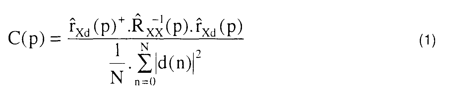
- multi-channel synchronization therefore requires, for each position p tested, the calculation of r and Xd (p), of R and XX (p), of the inverse of R and XX (P) and of the criterion r and Xd (p) + .R and XX -1 (p) .r and Xd (p).
- the matrix R and XX (p) is calculated and inverted every P positions, that is to say for the positions p 0 such as p, modulo P, be zero.
- the matrix is calculated by performing the correlation on N + P samples:
- the criterion C (p) is calculated using R and -1 / XX (p 0 ), the calculation of R and Xd (p) remaining unchanged.
- the second situation is less likely than the first, but it can occur in an urban or mountainous context.
- the simultaneous reception of signals transmitted in several cells is all the more likely the higher the altitude of the aircraft.
- the MUSIC method is based on the structure of the covariance matrix R XX , and it assumes that the noise b (t) is spatially white. This means that the noise level is the same on all the sensors, and that it is uncorrelated between two separate sensors.
- the signal space matrix L s is diagonal and has the dimension MxM.
- the directional vectors of the matrix A are linear combinations of the eigenvectors of the signal space Es, according to equation (8).
- the decomposition into eigen elements of R XX shows that the eigenvectors of the matrices E s and E b are orthogonal. Consequently, the directing vectors of the matrix A are orthogonal to those of the noise space E b .
- the P MUSIC function ( ⁇ , ⁇ ) is canceled for all the angles ( ⁇ m , ⁇ m ) of the incident sources.
- the expression of this function confirms that it is normalized between 0 and 1.
- the angles of elevation ⁇ m and of azimuth, m are corrected, taking into account the attitude and the orientation of the aircraft.
- the attitude and the orientation of the aircraft are provided by the inertial unit of the aircraft.
- the correction is carried out by regularly taking the measurement of the attitude of the aircraft.
- the attitude of the aircraft is expressed according to the instantaneous angles of roll, pitch and yaw.
- the corrected values of the elevation and azimuth angles are converted into geographic positions, called elementary plots.
- the corrected angles of elevation ⁇ m and of azimuth ⁇ m are given in the reference frame of the antennas relative to the aircraft.
- the conversion consists in transforming them into elevation and azimuth angles relative to the absolute geocentric coordinate system.
- the geographic positions are obtained by performing the intersection of the direction of arrival, associated with a site angle and an azimuth angle expressed in the absolute geocentric coordinate system, with a digital model of the terrain. The points of intersection are called elementary plots.
- the third step is to locate the transmitters from the elementary studs by tracking techniques.
- a characteristic of GSM transmitters is that each alternation communication system uses a set of bearings whose frequency is random.
- the usual radio-geographic tracking techniques do not can adapt to this inconsistent frequency. Only Adaptive tracking techniques can be used.
- the measures used, for the search for GSM transmitters are the basic measures taken from the on-board measurement chain, that is to say the elementary studs.
- GSM broadcasts have technical markers, which are used to group elementary measurements before localization Fine.
- Adaptive tracking uses image processing techniques to grouping by geographic segmentation of elementary measures.
- Image processing techniques consist of, a mesh operation, a geographic probability density calculation, filtering operations and segmentation operations by a construction of watersheds.
- the mesh operation performs the geographic mesh of geographic areas where the elementary plots are located.
- the method used for the density calculation is to calculate a histogram of measures.
- the measurement histogram is calculated on a state space. If, for example, the measurements are the intersections with the earth, and if the state space is the location on the surface of the earth, then, at each new measurement, the mesh of the state space where is located the measurement is incremented by one. For example, a mesh, in which are three measures, has a density of three.
- the method used for calculating the density consists in supposing that the vector of measurements follows a centered normal law. This density calculation is particularly suited to the low volumes of measurements generated by transmitters that are not very active.
- the covariance matrix of the measurement vector is known.
- the vector of measurements is supposed to follow a normal centered law.
- Each cell of the mesh of the state space is incremented by the value of the conditional density. If, for example, the measurements are the intersections with the earth, and if the state space is the location on the surface of the earth, then, with each new measurement, each cell i of the mesh of the space of state is incremented by a value p i .
- the distance between two successive meshes is preferably fixed at N times (1 ⁇ N ⁇ 3) an “average” standard deviation, sigma, of measurements taken on all elementary studs.
- Figure 10 illustrates the mesh around an elementary pad.
- the geographic density calculated above may present undesirable discontinuities for adaptive tracking treatments. For for this reason, a set of filter modules is used. Filtering performed by a module is either linear or morphological.
- a mask defining the local area of work is used. This local area is centered on each mesh of the geographic region to be treated. Local area defines neighbors geographic to consider for this mesh.
- Figure 11a illustrates a mask said, in 4-connectedness; the local area, centered on a mesh marked 0, includes four neighbors denoted 1, 2, 3 and 4.
- Figure 11b illustrates a mask says, in 8-connectedness; the local area, centered on a mesh marked 0, includes eight neighbors marked 1, 2, ..., 8.
- the opening and closing filters have a remarkable advantage; only one application of the filters is necessary because the filters are idempotent. This means that, unlike erosion and expansion, repeating these filters is useless, because the result obtained after repeating is identical to the result obtained after the first application.
- the filtering treatments have another characteristic of be able to be executed quickly; they require a single exploration of the image. They can be used at any time during operation to improve a calculated density.
- a digital image I n can be modeled as being a set of meshes, or blocks assimilated to elementary points of a real image; the tiles can be considered to be equivalent to pixels.
- the notion of catchment area C (M) associated with a minimum M is defined by, the set of pixels or meshes p of I n such that a drop of water falling in p flows along the relief of I n in following a descending path which brings it to the minimum M.
- FIG 12 illustrates the construction of the watersheds.
- the image I n is considered as a surface of which each of the minima has been drilled with a hole. This surface is slowly immersed in a body of water, assumed to be infinite for the convenience of the explanation. Water gradually fills the watersheds of I n through these hole minima, and in particular those at lower elevations. At all times during the flood, the different lakes delimited on the topography are at the same altitude. A dam is built at each place where the waters coming from two distinct minima meet. At the end of the immersion procedure, each minimum is completely surrounded by a dike which delimits the associated watershed. The segmentation into regions thus obtained is that of watersheds. The set of dykes defines the watershed. A known algorithm for constructing watersheds is described in document [3].
- the method of creating tracks, used for localization of GSM transmitters, is progressive and adaptive.
- the method can take place on several levels. Every level, the goal is to refine all the tracks generated during the levels precedents.
- the method consists in developing a first set of tracks, using the techniques previously described.
- all J tracks are examined, in order to create tracks where possible, or in order to increase the accuracy of existing tracks.
- the most reliable elementary measures are selected by sort; sorting is based on associated uncertainty ellipses with elementary studs.
- the threshold imposed during this sorting is adapted to the volume available measures. Draconian selection limits possibilities processing by providing little information. Conversely, a selection less severe is a source of imprecision of the final locations.
- a density calculation is performed on the meshed geographic area. The calculation of density by normal law assumption is particularly suitable for low volume of measurements generated by weakly active transmitters.
- a segmentation, by construction of watersheds is performed, on the density image. This segmentation delimits different areas of influence. Each zone constitutes a track, so that at the outcome of the first level J tracks are available; the J tracks correspond to the J regions.
- Each of the J tracks is reviewed at the next level in the aim to increase its accuracy, or in order to create new leads.
- a selection of measurements is made; the selection is based on the value of the ellipses of uncertainty.
- the selection allows a partition into two subsets, of the set of measures of the track; the score is adapted to the number of measures available.
- the selection threshold is set automatically, depending on the range of variation of the ellipses of uncertainty of the measurements of the track considered.
- Sure the selected measurements the process performs a density calculation, on the reduced area delimited by the geographic coordinates of the measurements. he is possible to detect new tracks, again using a segmentation by watershed on the reduced density of each track. If the segmentation operation detects multiple regions, new ones tracks are created. Each new track is then made up of a part measurements of the original track. However, if only one region is set in evidence, only the accuracy of this track is improved thanks to the selection made on the measures of this track.
- the number of levels of this method is variable, depending the degree of complexity of the problem.
- Fine localization performed after tracking, consists of detecting the density maxima of each track or to calculate the weighted barycenter elementary measurements (or elementary studs) of each track.
- the fine localization gives the position of the transmitters with an ellipse associated uncertainty.
Landscapes
- Physics & Mathematics (AREA)
- Engineering & Computer Science (AREA)
- General Physics & Mathematics (AREA)
- Radar, Positioning & Navigation (AREA)
- Remote Sensing (AREA)
- Mobile Radio Communication Systems (AREA)
- Radar Systems Or Details Thereof (AREA)
- Radio Relay Systems (AREA)
Abstract
Description
- une station mobile, ou MS qui est l'abréviation de l'expression anglo-saxonne « Mobile Station ».
- un sous-système radio, ou BSS qui est l'abréviation de l'expression anglo-saxonne « Base Station System ».
- un sous-système gestion et acheminement, ou NSS qui est l'abréviation de l'expression anglo-saxonne « Network and Switching Sub-System ».
- le MSC (abréviation des termes anglo-saxons « Mobile-services Switching Center ») : il s'agit du commutateur du service mobile chargé de l'acheminement des communications de, et vers les mobiles dans une cellule,
- le HLR (abréviation des termes anglo-saxons « Home Location Register») : il s'agit de la base de données où sont enregistrés les paramètres permanents d'un abonné ; le HLR contient par ailleurs l'information de localisation du mobile constamment à jour,
- le VLR (abréviation des termes anglo-saxons « Visitor Location Register ») : il s'agit de la base de donnée où est enregistrée la localisation fine du mobile en zone d'appel.
- à intercepter, à partir d'un aéronef, des signaux radioélectriques et à les détecter, en mettant en oeuvre une synchronisation multi-voies, pour déterminer les différentes sources d'émission,
- à calculer simultanément un angle de site Δ, et un angle d'azimut , pour déterminer instantanément la direction d'arrivée des signaux radioélectriques des sources d'émission déterminées,
- à construire des pistes dans les zones géographiques où se situent les sources d'émission, pour estimer la position des émetteurs.
- la figure 1, un réseau de radiocommunications de type GSM selon l'art antérieur,
- la figure 2, une configuration typique d'utilisation de stations mobiles MS, de stations de base BTS et d'un contrôleur de stations de base BSC selon l'art antérieur,
- la figure 3, un exemple de planification d'utilisation de fréquences avec un motif de réutilisation de quatre selon l'art antérieur,
- la figure 4, le procédé selon l'invention sous la forme d'un organigramme,
- la figure 5, une décomposition fonctionnelle d'un dispositif mettant en oeuvre le procédé selon l'invention,
- la figure 6, un tracé du critère PMUSIC (, Δ) pour deux sources d'incidence, 60 degrés et 100 degrés en azimut (), et 0 degré en site (Δ = 0),
- la figure 7, une goniométrie azimut-site,
- la figure 8, une première représentation d'un spectre du critère de MUSIC,
- la figure 9, une seconde représentation d'un spectre du critère de MUSIC,
- la figure 10, un exemple de maillage autour d'un plot,
- la figure 11a, un masque dit en 4-connexités,
- la figure 11b, un masque dit en 8-connexités,
- la figure 12, une illustration de la construction des lignes de partage des eaux.
- numérisation des signaux fournis par le récepteur multi-voies synchrone,
- stockage des signaux sur l'unité de stockage 13, avec une référence horaire commune,
- détermination de la liste des séquences de référence TSC , abréviation des termes anglo-saxons « Training Sequence Code », détectées sur le canal, ainsi que des niveaux de réception associés, et des positions de synchronisation,
- utilisation de ces positions de synchronisation afin de déterminer les angles d'arrivée,
- corrélation entre la position, l'assiette du porteur et les directions d'arrivée, afin de fournir par intersection terre des localisations élémentaires appelées plots,
- maillage d'une zone géographique et calcul de densité pour construire une image à partir des plots,
- regroupement des plots par pistage adaptatif qui affine progressivement les pistes,
- localisation des émetteurs par extraction des maxima ou calcul d'un barycentre pondéré des plots regroupés en pistes,
- affichage vers un utilisateur et acquisition de données saisies par l'utilisateur, au moyen de l'interface avec l'utilisateur 14.


- l'aéronef intercepte des signaux émis dans plusieurs cellules,
- ou, l'aéronef intercepte un signal ayant suivi plusieurs trajets ; la propagation est dite multi-trajets.

- une méthode avec histogramme des mesures,
- une méthode avec une hypothèse de loi normale : la matrice de covariance du vecteur de mesures est connu, et par hypothèse, le vecteur de mesures suit une loi normale centrée.


Claims (12)
- Procédé de localisation en temps réel d'émetteurs terrestres appartenant à un réseau de radiocommunications cellulaires de type TDMA, caractérisé en ce qu'il consiste :à intercepter (1), à partir d'un aéronef, des signaux radioélectriques et à les détecter (1), en mettant en oeuvre une synchronisation multi-voies, pour déterminer les différentes sources d'émission,à calculer (2) simultanément un angle de site (Δ), et un angle d'azimut (), pour déterminer instantanément la direction d'arrivée des signaux radioélectriques des sources d'émission déterminées,à construire des pistes (3) dans les zones géographiques où se situent les sources d'émission, pour estimer la position des émetteurs.
- Procédé de localisation temps réel d'émetteurs terrestres selon la revendication 1, caractérisé en ce qu'il consiste :à calculer (2), dans le repère géocentrique absolu, l'intersection des directions d'arrivée des signaux radioélectriques, des différentes sources d'émission, avec le sol, en mettant à contribution un modèle numérique de terrain, pour déterminer la position géographique des sources d'émission,
- Procédé de localisation temps réel d'émetteurs terrestres selon l'une quelconque des revendications 1 et 2, caractérisé en ce qu'il consiste à détecter la présence de bursts de trafic (TCH) en reconnaissant des séquences d'apprentissage présentes dans les formes d'onde utilisant la norme GSM ou la norme DCS1800, pour synchroniser les signaux radioélectriques.
- Procédé de localisation temps réel d'émetteurs terrestres selon l'une quelconque des revendications 1 à 3, caractérisé en ce qu'il consiste à mettre en oeuvre une goniométrie haute résolution, pour déterminer l'incidence (m,Δm) de la direction d'arrivée des signaux radioélectriques dans un repère de l'aéronef.
- Procédé de localisation temps réel d'émetteurs terrestres selon la revendication 4, caractérisé en ce que la goniométrie est de type MUSIC et la recherche des incidences (m,Δm) consiste à minimiser, suivant l'azimut () et le site (Δ), le critère de MUSIC : PMUSIC (, Δ).
- Procédé de localisation temps réel d'émetteurs terrestres selon l'une quelconque des revendications 4 et 5, caractérisé en ce qu'il consiste à convertir l'incidence (, Δ), déterminée dans le repère de l'aéronef, dans le repère géocentrique absolu en tenant compte de l'attitude de l'aéronef.
- Procédé de localisation temps réel d'émetteurs terrestres selon l'une quelconque des revendications 1 à 6, caractérisé en ce qu'il consiste à calculer la densité de probabilité en mettant en oeuvre une méthode d'histogramme des mesures, les mesures étant les points d'intersection avec le sol.
- Procédé de localisation temps réel d'émetteurs terrestres selon l'une quelconque des revendications 1 à 7, caractérisé en ce qu'il consiste à filtrer la densité de probabilité en mettant en oeuvre un filtre linéaire.
- Procédé de localisation temps réel d'émetteurs terrestres selon l'une quelconque des revendications 1 à 7, caractérisé en ce qu'il consiste à filtrer la densité de probabilité en mettant en oeuvre un filtre morphologique.
- Procédé de localisation temps réel d'émetteurs terrestres selon l'une quelconque des revendications 1 à 9, caractérisé en ce qu'il consiste à segmenter les images de densité en construisant des lignes de partage des eaux, pour construire des pistes.
- Utilisation à bord d'un aéronef de moyens de traitement (4, 5, 6, 7, 8) de signaux radioélectriques provenant d'émetteurs radioélectriques terrestres, appartenant à un réseau de radiocommunications cellulaires de type TDMA, pour la mise en oeuvre du procédé selon l'une quelconque des revendications précédentes.
- Dispositif de localisation temps réel d'émetteurs radioélectriques terrestres pour la mise en oeuvre du procédé selon l'une des revendications précédentes, caractérisé en ce qu'il comprend :un réseau d'antennes (4) réparties sur un aéronef, pour capter les signaux radioélectriques,un récepteur multi-voies (5), pour réceptionner les signaux de sorties du réseau d'antennes (4) et synchroniser les signaux reçus,un calculateur de traitement numérique (8), pour traiter les signaux synchronisés et localiser les émetteurs de signaux radioélectriques captés,un système de gestion horaire (6), pour donner une référence temporelle commune au récepteur multi-voies (5) et au calculateur de traitement numérique (8),un système de localisation et de détection de l'assiette de l'aéronef (7), pour fournir l'attitude de l'avion dans le repère géocentrique absolu, au calculateur de traitement numérique (8),
Applications Claiming Priority (2)
| Application Number | Priority Date | Filing Date | Title |
|---|---|---|---|
| FR9902244 | 1999-02-23 | ||
| FR9902244A FR2790098B1 (fr) | 1999-02-23 | 1999-02-23 | Procede de localisation de radios mobiles terrestres a partir d'un aeronef |
Publications (2)
| Publication Number | Publication Date |
|---|---|
| EP1031847A1 true EP1031847A1 (fr) | 2000-08-30 |
| EP1031847B1 EP1031847B1 (fr) | 2006-06-07 |
Family
ID=9542427
Family Applications (1)
| Application Number | Title | Priority Date | Filing Date |
|---|---|---|---|
| EP00400453A Expired - Lifetime EP1031847B1 (fr) | 1999-02-23 | 2000-02-18 | Procédé de localisation de radios mobiles terrestres a partir d'un aeronef |
Country Status (6)
| Country | Link |
|---|---|
| US (1) | US6714782B1 (fr) |
| EP (1) | EP1031847B1 (fr) |
| AT (1) | ATE329276T1 (fr) |
| CA (1) | CA2299136A1 (fr) |
| DE (1) | DE60028433T2 (fr) |
| FR (1) | FR2790098B1 (fr) |
Cited By (6)
| Publication number | Priority date | Publication date | Assignee | Title |
|---|---|---|---|---|
| EP1253799A1 (fr) * | 2001-04-27 | 2002-10-30 | Thales | Procédé et dispositif de localisation d'un mobile au sein d'un reseau de communication |
| EP1253436A1 (fr) * | 2001-04-27 | 2002-10-30 | Thales | Système et procédé de localisation de radiomobiles en dehors de la couverture d'un réseau cellulaire |
| FR2829241A1 (fr) * | 2001-09-05 | 2003-03-07 | Thales Sa | Procede et dispositif de radiogoniometrie cooperative en transmission |
| RU2373551C1 (ru) * | 2008-03-24 | 2009-11-20 | Федеральное агентство по образованию Государственное образовательное учреждение высшего профессионального образования Рязанский государственный радиотехнический университет | Способ измерения угловых координат нескольких объектов в многоканальных доплеровских рлс |
| US9918545B2 (en) | 2013-02-04 | 2018-03-20 | Bakkerelkhuizen Innovations B.V. | Stand for a portable device with a graphic user interface display |
| RU2661913C1 (ru) * | 2017-03-10 | 2018-07-23 | Федеральное государственное бюджетное образовательное учреждение высшего образования "Рязанский государственный радиотехнический университет" | Способ выделения спектральных отсчетов в многоканальной доплеровской рлс |
Families Citing this family (19)
| Publication number | Priority date | Publication date | Assignee | Title |
|---|---|---|---|---|
| US8446321B2 (en) | 1999-03-05 | 2013-05-21 | Omnipol A.S. | Deployable intelligence and tracking system for homeland security and search and rescue |
| US7908077B2 (en) * | 2003-06-10 | 2011-03-15 | Itt Manufacturing Enterprises, Inc. | Land use compatibility planning software |
| US7889133B2 (en) | 1999-03-05 | 2011-02-15 | Itt Manufacturing Enterprises, Inc. | Multilateration enhancements for noise and operations management |
| US7612716B2 (en) | 1999-03-05 | 2009-11-03 | Era Systems Corporation | Correlation of flight track data with other data sources |
| US7782256B2 (en) * | 1999-03-05 | 2010-08-24 | Era Systems Corporation | Enhanced passive coherent location techniques to track and identify UAVs, UCAVs, MAVs, and other objects |
| US7570214B2 (en) | 1999-03-05 | 2009-08-04 | Era Systems, Inc. | Method and apparatus for ADS-B validation, active and passive multilateration, and elliptical surviellance |
| US8203486B1 (en) | 1999-03-05 | 2012-06-19 | Omnipol A.S. | Transmitter independent techniques to extend the performance of passive coherent location |
| US7667647B2 (en) * | 1999-03-05 | 2010-02-23 | Era Systems Corporation | Extension of aircraft tracking and positive identification from movement areas into non-movement areas |
| US7777675B2 (en) * | 1999-03-05 | 2010-08-17 | Era Systems Corporation | Deployable passive broadband aircraft tracking |
| US7739167B2 (en) | 1999-03-05 | 2010-06-15 | Era Systems Corporation | Automated management of airport revenues |
| US6917880B2 (en) * | 2001-06-29 | 2005-07-12 | Information Systems Laboratories, Inc. | Intelligent passive navigation system for back-up and verification of GPS |
| US7965227B2 (en) | 2006-05-08 | 2011-06-21 | Era Systems, Inc. | Aircraft tracking using low cost tagging as a discriminator |
| WO2014119992A1 (fr) | 2013-02-04 | 2014-08-07 | Bakkerelkhuizen Innovations B.V. | Support pour dispositif portable, doté d'un affichage d'interface utilisateur graphique |
| ES2869858T3 (es) * | 2013-05-08 | 2021-10-26 | Airbus Defence & Space Gmbh | Evaluación de la posición de un vehículo aéreo |
| EP3111127B1 (fr) | 2014-02-28 | 2020-01-22 | Oahwip B.V. | Socle pour dispositif portable à affichage d'interface utilisateur graphique |
| FR3041766B1 (fr) * | 2015-09-25 | 2019-03-29 | Thales | Procede de localisation passive d'emetteurs electromagnetiques au sol, utilisation, et dispositif associe |
| KR102649597B1 (ko) * | 2019-01-02 | 2024-03-20 | 한국전자통신연구원 | 무인 비행체를 이용한 신호원의 위치정보 확인 방법 및 장치 |
| CN115001602B (zh) * | 2022-05-07 | 2023-05-09 | 成都美数科技有限公司 | 一种多通道接收机误差动态修正方法、系统、终端及介质 |
| CN114814720B (zh) * | 2022-06-20 | 2022-09-30 | 成都市克莱微波科技有限公司 | 微波测向装置、系统、方法及存储介质 |
Citations (3)
| Publication number | Priority date | Publication date | Assignee | Title |
|---|---|---|---|---|
| FR2721410A1 (fr) * | 1994-06-16 | 1995-12-22 | Alcatel Espace | Méthode et système de localisation d'équipements sol émetteurs à l'aide de satellites. |
| FR2721459A1 (fr) * | 1994-06-21 | 1995-12-22 | Alcatel Mobile Comm France | Procédé de radiolocalisation d'un mobile à l'aide d'un satellite, dispositif de radiolocalisation, et procédé d'émission correspondants. |
| FR2766320A1 (fr) * | 1997-07-15 | 1999-01-22 | Thomson Csf | Procede et dispositif d'analyse des interferences dans un systeme de radiocommunication cellulaire |
Family Cites Families (12)
| Publication number | Priority date | Publication date | Assignee | Title |
|---|---|---|---|---|
| US5515378A (en) * | 1991-12-12 | 1996-05-07 | Arraycomm, Inc. | Spatial division multiple access wireless communication systems |
| US5457466A (en) * | 1993-09-07 | 1995-10-10 | Litton Systems Inc. | Emitter azimuth and elevation direction finding using only linear interferometer arrays |
| US5559806A (en) * | 1995-02-27 | 1996-09-24 | Motorola, Inc. | Transceiver having steerable antenna and associated method |
| FR2732490B1 (fr) | 1995-03-28 | 1997-04-25 | Thomson Csf | Procede de reception multicapteur d'une station de base d'un reseau de communication echangeant des donnees avec des mobiles, et dispositif pour sa mise en oeuvre |
| US5774087A (en) * | 1997-02-20 | 1998-06-30 | Litton Systems Inc. | Apparatus for measuring moving emitter elevation and azimuth direction from doppler change measurements |
| FR2764074B1 (fr) | 1997-06-03 | 1999-08-20 | Thomson Csf | Procede et dispositif de radiogoniometrie cooperative en transmission |
| US6011974A (en) * | 1997-09-23 | 2000-01-04 | Telefonaktiebolaget L M Ericsson (Publ) | Method and system for determining position of a cellular mobile terminal |
| US5907302A (en) * | 1997-12-19 | 1999-05-25 | The United States Of America As Represented By The Secretary Of The Air Force | Adaptive elevational scan processor statement of government interest |
| US5999129A (en) * | 1998-06-01 | 1999-12-07 | Litton Systems, Inc. | Multiplatform ambiguous phase circle and TDOA protection emitter location |
| GB2339078B (en) * | 1998-07-02 | 2003-07-02 | Secr Defence | Adaptive sensor array apparatus |
| US6239747B1 (en) * | 1999-03-11 | 2001-05-29 | Lucent Technologies Inc. | Antenna system and method for direction finding |
| US6061022A (en) * | 1999-06-04 | 2000-05-09 | Itt Manufacturing Enterprises, Inc. | Azimuth and elevation direction finding system based on hybrid amplitude/phase comparison |
-
1999
- 1999-02-23 FR FR9902244A patent/FR2790098B1/fr not_active Expired - Lifetime
-
2000
- 2000-02-18 EP EP00400453A patent/EP1031847B1/fr not_active Expired - Lifetime
- 2000-02-18 DE DE60028433T patent/DE60028433T2/de not_active Expired - Lifetime
- 2000-02-18 AT AT00400453T patent/ATE329276T1/de not_active IP Right Cessation
- 2000-02-22 CA CA002299136A patent/CA2299136A1/fr not_active Abandoned
- 2000-02-23 US US09/511,911 patent/US6714782B1/en not_active Expired - Fee Related
Patent Citations (3)
| Publication number | Priority date | Publication date | Assignee | Title |
|---|---|---|---|---|
| FR2721410A1 (fr) * | 1994-06-16 | 1995-12-22 | Alcatel Espace | Méthode et système de localisation d'équipements sol émetteurs à l'aide de satellites. |
| FR2721459A1 (fr) * | 1994-06-21 | 1995-12-22 | Alcatel Mobile Comm France | Procédé de radiolocalisation d'un mobile à l'aide d'un satellite, dispositif de radiolocalisation, et procédé d'émission correspondants. |
| FR2766320A1 (fr) * | 1997-07-15 | 1999-01-22 | Thomson Csf | Procede et dispositif d'analyse des interferences dans un systeme de radiocommunication cellulaire |
Cited By (12)
| Publication number | Priority date | Publication date | Assignee | Title |
|---|---|---|---|---|
| EP1253799A1 (fr) * | 2001-04-27 | 2002-10-30 | Thales | Procédé et dispositif de localisation d'un mobile au sein d'un reseau de communication |
| EP1253436A1 (fr) * | 2001-04-27 | 2002-10-30 | Thales | Système et procédé de localisation de radiomobiles en dehors de la couverture d'un réseau cellulaire |
| FR2824207A1 (fr) * | 2001-04-27 | 2002-10-31 | Thomson Csf | Procede et dispositif de localisation d'un mobile au sein d'un reseau de communication |
| FR2824146A1 (fr) * | 2001-04-27 | 2002-10-31 | Thomson Csf | Systeme et procede de localisation de radiomobiles en dehors de la couverture d'un reseau cellulaire |
| US6999728B2 (en) | 2001-04-27 | 2006-02-14 | Thales | Method and device for the location of a mobile telephone in a communications network |
| US7398086B2 (en) | 2001-04-27 | 2008-07-08 | Thales | System and method to locate radiomobiles outside the coverage of a cellular network |
| FR2829241A1 (fr) * | 2001-09-05 | 2003-03-07 | Thales Sa | Procede et dispositif de radiogoniometrie cooperative en transmission |
| EP1291664A1 (fr) | 2001-09-05 | 2003-03-12 | Thales | Procédé et dispositif de radiogoniometrie cooperative en transmission |
| US6693591B2 (en) | 2001-09-05 | 2004-02-17 | Thales | Method and device for co-operative radio direction-finding in transmission |
| RU2373551C1 (ru) * | 2008-03-24 | 2009-11-20 | Федеральное агентство по образованию Государственное образовательное учреждение высшего профессионального образования Рязанский государственный радиотехнический университет | Способ измерения угловых координат нескольких объектов в многоканальных доплеровских рлс |
| US9918545B2 (en) | 2013-02-04 | 2018-03-20 | Bakkerelkhuizen Innovations B.V. | Stand for a portable device with a graphic user interface display |
| RU2661913C1 (ru) * | 2017-03-10 | 2018-07-23 | Федеральное государственное бюджетное образовательное учреждение высшего образования "Рязанский государственный радиотехнический университет" | Способ выделения спектральных отсчетов в многоканальной доплеровской рлс |
Also Published As
| Publication number | Publication date |
|---|---|
| US6714782B1 (en) | 2004-03-30 |
| DE60028433D1 (de) | 2006-07-20 |
| DE60028433T2 (de) | 2007-01-11 |
| FR2790098A1 (fr) | 2000-08-25 |
| EP1031847B1 (fr) | 2006-06-07 |
| CA2299136A1 (fr) | 2000-08-23 |
| FR2790098B1 (fr) | 2001-05-11 |
| ATE329276T1 (de) | 2006-06-15 |
Similar Documents
| Publication | Publication Date | Title |
|---|---|---|
| EP1031847B1 (fr) | Procédé de localisation de radios mobiles terrestres a partir d'un aeronef | |
| EP0931429B1 (fr) | Procede et dispositif d'analyse des interferences dans un systeme de radiocommunication cellulaire | |
| Papi et al. | Radiolocation and tracking of automatic identification system signals for maritime situational awareness | |
| Muckenhuber et al. | Open-source sea ice drift algorithm for Sentinel-1 SAR imagery using a combination of feature tracking and pattern matching | |
| EP2362555B1 (fr) | Procédé de recouvrement d'un signal parmi un ensemble de signaux collectes par satellite | |
| EP3399328B1 (fr) | Procédé et système de localisation distribué phdoa, pwdoa, de sources émettrices | |
| CA2382415C (fr) | Systeme et procede de localisation de radiomobiles en dehors de la couverture d'un reseau cellulaire | |
| EP0681190A1 (fr) | Procédé de détection radar discrète et système de mise en oeuvre | |
| EP2974431B1 (fr) | Procédé de prédiction du niveau de champ radio et/ou de la durée de propagation des réseaux de téléphonie cellulaire utilisant des bases de données terrain à haute résolution | |
| FR2960364A1 (fr) | Systeme de telecommunication par satellite comportant un mecanisme de separation de messages emis par une pluralite d'emetteurs | |
| EP1671152A1 (fr) | Procede et dispositif de filtrage de reponses dans un extracteur de radar secondaire | |
| FR2834563A1 (fr) | Procede de suppression de signaux radioelectriques pulses et dispositif de mise en oeuvre du procede | |
| Xie et al. | Evaluating ICESat-2 seafloor photons by underwater light-beam propagation and noise modeling | |
| CN116828391B (zh) | 一种检测ais异常开关的方法 | |
| Portilla-Yandún et al. | A hybrid physical-statistical algorithm for SAR wave spectra quality assessment | |
| Dabaghi Daryan et al. | Intelligent mitigation of GPS spoofing using the Kalman filter in the tracking loop based on multi-correlator | |
| CN119416125A (zh) | 一种基于机器学习的无线电信号识别方法及系统 | |
| EP1253799A1 (fr) | Procédé et dispositif de localisation d'un mobile au sein d'un reseau de communication | |
| WO2017098128A1 (fr) | Systeme d'analyse spatio-temporelle des flux d'objets mobiles | |
| POHONTU et al. | Detection of spoofed AIS: Simulated tracks vs. real maritime data | |
| EP3420642B1 (fr) | Capteur intégré d'interception des émissions radioélectriques com/rad | |
| EP3839550A1 (fr) | Procede de geolocalisation d'objets connectes et dispositif associe | |
| Sun et al. | Retrieving telemetry range from ICESat-2 data by a no-prior-terrain onboard filtering algorithm | |
| EP0330541B1 (fr) | Procédé et dispositif de radiolocalisation et leurs utilisations dans des systèmes de radiocommunication | |
| EP4073465B1 (fr) | Filtrage particulaire et centrale de navigation a correlation de mesure |
Legal Events
| Date | Code | Title | Description |
|---|---|---|---|
| PUAI | Public reference made under article 153(3) epc to a published international application that has entered the european phase |
Free format text: ORIGINAL CODE: 0009012 |
|
| AK | Designated contracting states |
Kind code of ref document: A1 Designated state(s): AT BE CH CY DE DK ES FI FR GB GR IE IT LI LU MC NL PT SE |
|
| AX | Request for extension of the european patent |
Free format text: AL;LT;LV;MK;RO;SI |
|
| 17P | Request for examination filed |
Effective date: 20010130 |
|
| AKX | Designation fees paid |
Free format text: AT BE CH CY DE DK ES FI FR GB GR IE IT LI LU MC NL PT SE |
|
| RAP1 | Party data changed (applicant data changed or rights of an application transferred) |
Owner name: THALES |
|
| 17Q | First examination report despatched |
Effective date: 20050426 |
|
| GRAP | Despatch of communication of intention to grant a patent |
Free format text: ORIGINAL CODE: EPIDOSNIGR1 |
|
| GRAS | Grant fee paid |
Free format text: ORIGINAL CODE: EPIDOSNIGR3 |
|
| GRAA | (expected) grant |
Free format text: ORIGINAL CODE: 0009210 |
|
| AK | Designated contracting states |
Kind code of ref document: B1 Designated state(s): AT BE CH CY DE DK ES FI FR GB GR IE IT LI LU MC NL PT SE |
|
| PG25 | Lapsed in a contracting state [announced via postgrant information from national office to epo] |
Ref country code: AT Free format text: LAPSE BECAUSE OF FAILURE TO SUBMIT A TRANSLATION OF THE DESCRIPTION OR TO PAY THE FEE WITHIN THE PRESCRIBED TIME-LIMIT Effective date: 20060607 Ref country code: NL Free format text: LAPSE BECAUSE OF FAILURE TO SUBMIT A TRANSLATION OF THE DESCRIPTION OR TO PAY THE FEE WITHIN THE PRESCRIBED TIME-LIMIT Effective date: 20060607 Ref country code: IE Free format text: LAPSE BECAUSE OF FAILURE TO SUBMIT A TRANSLATION OF THE DESCRIPTION OR TO PAY THE FEE WITHIN THE PRESCRIBED TIME-LIMIT Effective date: 20060607 Ref country code: FI Free format text: LAPSE BECAUSE OF FAILURE TO SUBMIT A TRANSLATION OF THE DESCRIPTION OR TO PAY THE FEE WITHIN THE PRESCRIBED TIME-LIMIT Effective date: 20060607 Ref country code: IT Free format text: LAPSE BECAUSE OF FAILURE TO SUBMIT A TRANSLATION OF THE DESCRIPTION OR TO PAY THE FEE WITHIN THE PRESCRIBED TIME-LIMIT;WARNING: LAPSES OF ITALIAN PATENTS WITH EFFECTIVE DATE BEFORE 2007 MAY HAVE OCCURRED AT ANY TIME BEFORE 2007. THE CORRECT EFFECTIVE DATE MAY BE DIFFERENT FROM THE ONE RECORDED. Effective date: 20060607 |
|
| REG | Reference to a national code |
Ref country code: GB Ref legal event code: FG4D Free format text: NOT ENGLISH |
|
| REG | Reference to a national code |
Ref country code: CH Ref legal event code: EP |
|
| REG | Reference to a national code |
Ref country code: IE Ref legal event code: FG4D Free format text: LANGUAGE OF EP DOCUMENT: FRENCH |
|
| REF | Corresponds to: |
Ref document number: 60028433 Country of ref document: DE Date of ref document: 20060720 Kind code of ref document: P |
|
| PG25 | Lapsed in a contracting state [announced via postgrant information from national office to epo] |
Ref country code: DK Free format text: LAPSE BECAUSE OF FAILURE TO SUBMIT A TRANSLATION OF THE DESCRIPTION OR TO PAY THE FEE WITHIN THE PRESCRIBED TIME-LIMIT Effective date: 20060907 |
|
| PG25 | Lapsed in a contracting state [announced via postgrant information from national office to epo] |
Ref country code: ES Free format text: LAPSE BECAUSE OF FAILURE TO SUBMIT A TRANSLATION OF THE DESCRIPTION OR TO PAY THE FEE WITHIN THE PRESCRIBED TIME-LIMIT Effective date: 20060918 |
|
| REG | Reference to a national code |
Ref country code: SE Ref legal event code: TRGR |
|
| GBT | Gb: translation of ep patent filed (gb section 77(6)(a)/1977) |
Effective date: 20060923 |
|
| PG25 | Lapsed in a contracting state [announced via postgrant information from national office to epo] |
Ref country code: PT Free format text: LAPSE BECAUSE OF FAILURE TO SUBMIT A TRANSLATION OF THE DESCRIPTION OR TO PAY THE FEE WITHIN THE PRESCRIBED TIME-LIMIT Effective date: 20061107 |
|
| NLV1 | Nl: lapsed or annulled due to failure to fulfill the requirements of art. 29p and 29m of the patents act | ||
| REG | Reference to a national code |
Ref country code: IE Ref legal event code: FD4D |
|
| PG25 | Lapsed in a contracting state [announced via postgrant information from national office to epo] |
Ref country code: LI Free format text: LAPSE BECAUSE OF NON-PAYMENT OF DUE FEES Effective date: 20070228 Ref country code: CH Free format text: LAPSE BECAUSE OF NON-PAYMENT OF DUE FEES Effective date: 20070228 Ref country code: MC Free format text: LAPSE BECAUSE OF NON-PAYMENT OF DUE FEES Effective date: 20070228 |
|
| PLBE | No opposition filed within time limit |
Free format text: ORIGINAL CODE: 0009261 |
|
| STAA | Information on the status of an ep patent application or granted ep patent |
Free format text: STATUS: NO OPPOSITION FILED WITHIN TIME LIMIT |
|
| 26N | No opposition filed |
Effective date: 20070308 |
|
| REG | Reference to a national code |
Ref country code: CH Ref legal event code: PL |
|
| BERE | Be: lapsed |
Owner name: THALES Effective date: 20070228 |
|
| PG25 | Lapsed in a contracting state [announced via postgrant information from national office to epo] |
Ref country code: BE Free format text: LAPSE BECAUSE OF NON-PAYMENT OF DUE FEES Effective date: 20070228 |
|
| PG25 | Lapsed in a contracting state [announced via postgrant information from national office to epo] |
Ref country code: GR Free format text: LAPSE BECAUSE OF FAILURE TO SUBMIT A TRANSLATION OF THE DESCRIPTION OR TO PAY THE FEE WITHIN THE PRESCRIBED TIME-LIMIT Effective date: 20060908 |
|
| PG25 | Lapsed in a contracting state [announced via postgrant information from national office to epo] |
Ref country code: LU Free format text: LAPSE BECAUSE OF NON-PAYMENT OF DUE FEES Effective date: 20070218 Ref country code: CY Free format text: LAPSE BECAUSE OF FAILURE TO SUBMIT A TRANSLATION OF THE DESCRIPTION OR TO PAY THE FEE WITHIN THE PRESCRIBED TIME-LIMIT Effective date: 20060607 |
|
| REG | Reference to a national code |
Ref country code: FR Ref legal event code: PLFP Year of fee payment: 17 |
|
| PGFP | Annual fee paid to national office [announced via postgrant information from national office to epo] |
Ref country code: DE Payment date: 20160209 Year of fee payment: 17 Ref country code: IT Payment date: 20160222 Year of fee payment: 17 |
|
| PGFP | Annual fee paid to national office [announced via postgrant information from national office to epo] |
Ref country code: SE Payment date: 20160211 Year of fee payment: 17 Ref country code: GB Payment date: 20160217 Year of fee payment: 17 |
|
| REG | Reference to a national code |
Ref country code: FR Ref legal event code: PLFP Year of fee payment: 18 |
|
| REG | Reference to a national code |
Ref country code: DE Ref legal event code: R119 Ref document number: 60028433 Country of ref document: DE |
|
| REG | Reference to a national code |
Ref country code: SE Ref legal event code: EUG |
|
| GBPC | Gb: european patent ceased through non-payment of renewal fee |
Effective date: 20170218 |
|
| PG25 | Lapsed in a contracting state [announced via postgrant information from national office to epo] |
Ref country code: SE Free format text: LAPSE BECAUSE OF NON-PAYMENT OF DUE FEES Effective date: 20170219 |
|
| REG | Reference to a national code |
Ref country code: FR Ref legal event code: PLFP Year of fee payment: 19 |
|
| PG25 | Lapsed in a contracting state [announced via postgrant information from national office to epo] |
Ref country code: DE Free format text: LAPSE BECAUSE OF NON-PAYMENT OF DUE FEES Effective date: 20170901 |
|
| PG25 | Lapsed in a contracting state [announced via postgrant information from national office to epo] |
Ref country code: GB Free format text: LAPSE BECAUSE OF NON-PAYMENT OF DUE FEES Effective date: 20170218 Ref country code: IT Free format text: LAPSE BECAUSE OF NON-PAYMENT OF DUE FEES Effective date: 20170218 |
|
| PGFP | Annual fee paid to national office [announced via postgrant information from national office to epo] |
Ref country code: FR Payment date: 20190125 Year of fee payment: 20 |