EP1031425B1 - Printing apparatus and suction recovery control method - Google Patents
Printing apparatus and suction recovery control method Download PDFInfo
- Publication number
- EP1031425B1 EP1031425B1 EP00301421A EP00301421A EP1031425B1 EP 1031425 B1 EP1031425 B1 EP 1031425B1 EP 00301421 A EP00301421 A EP 00301421A EP 00301421 A EP00301421 A EP 00301421A EP 1031425 B1 EP1031425 B1 EP 1031425B1
- Authority
- EP
- European Patent Office
- Prior art keywords
- ink
- printing
- printhead
- timing
- Prior art date
- Legal status (The legal status is an assumption and is not a legal conclusion. Google has not performed a legal analysis and makes no representation as to the accuracy of the status listed.)
- Expired - Lifetime
Links
Images


Classifications
-
- B—PERFORMING OPERATIONS; TRANSPORTING
- B41—PRINTING; LINING MACHINES; TYPEWRITERS; STAMPS
- B41J—TYPEWRITERS; SELECTIVE PRINTING MECHANISMS, i.e. MECHANISMS PRINTING OTHERWISE THAN FROM A FORME; CORRECTION OF TYPOGRAPHICAL ERRORS
- B41J2/00—Typewriters or selective printing mechanisms characterised by the printing or marking process for which they are designed
- B41J2/005—Typewriters or selective printing mechanisms characterised by the printing or marking process for which they are designed characterised by bringing liquid or particles selectively into contact with a printing material
- B41J2/01—Ink jet
- B41J2/135—Nozzles
- B41J2/165—Preventing or detecting of nozzle clogging, e.g. cleaning, capping or moistening for nozzles
- B41J2/16517—Cleaning of print head nozzles
- B41J2/1652—Cleaning of print head nozzles by driving a fluid through the nozzles to the outside thereof, e.g. by applying pressure to the inside or vacuum at the outside of the print head
- B41J2/16532—Cleaning of print head nozzles by driving a fluid through the nozzles to the outside thereof, e.g. by applying pressure to the inside or vacuum at the outside of the print head by applying vacuum only
Definitions
- the present invention relates to a printing apparatus and suction recovery control method, and more particularly, to a printing apparatus employing a printhead which performs printing in accordance with an ink-jet printing method, and suction recovery control method.
- a printing apparatus employed in a printer or a printer unit of a copy machine or facsimile apparatus or the like, prints an image based on inputted image data by forming dot patterns on a print medium, e.g., paper, thin plastic sheet, fabric or the like.
- a print medium e.g., paper, thin plastic sheet, fabric or the like.
- Such printing apparatus can be categorized according to printing methods, e.g., ink-jet method, wire dot method, thermal-transfer method, laser-beam method and so on.
- the type employing ink-jet printing method which performs printing by discharging ink from a printhead to a print medium is advantageous, not only because printing can be performed with high precision at high speed, but because printing can be performed with low noise by virtue of the non-impact method, and color images can easily be printed with multiple colors of ink.
- ink is heated to cause film boiling and ink is discharged by pressure of bubbles generated by the film boiling.
- the bubble-jet method is known to realize high resolution printing and high speed printing even more easily.
- An ink-jet printing apparatus using ink as a recording material for printing, attributes importance to reliability maintenance for the ink discharge function of a printhead, in order to prevent negative influence on printing, caused by ink evaporation or bubble mixture in ink.
- the ink-jet printing apparatus comprises a cap for capping the printhead, and a head recovery unit having a suction pump for sucking ink inside the cap.
- the ink discharge surface of the printhead is capped at the position where the printhead faces against the cap, and the suction pump sucks bubbles inside the printhead.
- the suction recovery processing is an important technique for reliability maintenance of the ink-jet printing apparatus.
- the conventional ink-jet printing apparatus counts the number of times of discharge, or times the non-printing state period of the apparatus, or executes both, so that the suction is performed while the bubble volume is as constant as possible, and then controls suction operation in accordance with the counted values.
- the timing of suction operation of the printhead is determined based on the point of time whichever earlier: at which a predetermined time has elapsed from an initial point of time, or at which a predetermined amount of printing is completed from the initial point of time.
- Japanese Patent Application Laid-Open (KOKAI) No. 6-238914 proposes a method of determining timing of suction operation of a printhead based on the number of times of discharge, non-printing state period of the printer, and temperature of the printhead, taking into account a difference in the bubble generation amount in the head caused by a temperature rise inside the printhead.
- the reliability maintenance employed in the conventional ink-jet printing apparatus does not consider the number of times of discharge per unit printing area of a printhead (e.g., actual number of times of discharge while an image corresponding to one line is printed on A4-size paper.
- a print image duty e.g., actual number of times of discharge while an image corresponding to one line is printed on A4-size paper.
- suction operation is unnecessarily performed, causing to reduce the throughput of the printing apparatus or increase the amount of wasted ink, or causing discharge failure by bubbles before suction operation is performed.
- the bubble-jet method employs a method of locally heating ink to cause film boiling to generate ink discharge energy.
- the internal temperature of the printhead gradually rises as printing operation is performed, and as a result of the temperature rise, the generation state or growth rate of bubbles changes.
- the conventional example proposes a method of determining the timing of suction operation of the printhead based on the number of times of discharge, non-printing state period of the printer, and printhead temperature.
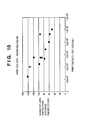
- Fig. 10 shows a relation between the number of lines printed by a printhead before discharge failure occurs, and a print time duty. Note that the print time duty is the number of print dots per unit time (dot/second).
- the internal temperature of the printhead is further taken into consideration, the case where the number of print dots per unit time is large and the internal temperature is low is more likely to cause discharge failure than the case where the number of print dots per unit time is small and the internal temperature is high.
- mass-produced ink-jet printheads differ in various printing characteristics. Therefore, even in a case where the same print data is inputted to print the same image, consideration must be given in that there may be a printhead which easily raises temperature and a printhead which does not easily raise temperature. Therefore, despite execution of temperature rise detection, the printhead which does not easily raise temperature is more likely to allow printing than the printhead which easily raises temperature. In other words, the printhead which does not easily raise temperature is more likely to perform printing consecutively or perform a number of times of printing within the unit time than the printhead which easily raises temperature.
- the printhead which has a low temperature and does not easily raise the temperature is more likely to cause discharge failure by bubbles in the printhead, than the printhead which has a high temperature and easily raises the temperature.
- an ink-jet printing apparatus raises a problem in that the conventional temperature rise detection cannot sufficiently prevent discharge failure because there are cases where discharge failure due to bubbles in the printhead occurs when a printhead has a low temperature rather than a high temperature.
- the printhead temperature (detected temperature) detected by the sensor of the printing apparatus is low, there may be cases that the actual printhead temperature is higher than the detected temperature. In this case, suction operation is not performed, causing discharge failure. On the contrary, even if the printhead temperature (detected temperature) detected by the sensor of the printing apparatus is high, there may be cases that the actual printhead temperature is lower than the detected temperature. In this case, the number of times of suction operation may unnecessarily increase, resulting in a reduced throughput of printing operation and the increased amount of wasted ink.
- the timing of suction operation cannot accurately be determined depending on the printing pattern.
- the printhead temperature detected at the end of printing the pattern on the print medium is relatively low compared to a case of printing a pattern having a uniform print image duty on the entire print medium. Because of this, suction operation is not performed, causing discharge failure.
- the printhead temperature detected at the end of printing the pattern on the print medium is relatively high compared to a case of printing a pattern having a uniform print image duty on the entire print medium- Because of this, the number of times of suction operation may unnecessarily increase, resulting in a reduced throughput of printing operation and the increased amount of wasted ink.
- suction recovery operation may cause to change the state of ink in a printhead. Therefore, if suction recovery operation is performed during printing of one page of print medium, tonality of an image printed on the print medium may change. For this reason, it is not preferable to execute suction recovery operation during printing of one page ot print medium.
- EP-A-0 589 581 describes a print rate control technique for power management, and a pen servicing technique for determining appropriate service intervals for plural pen ink-jet printers. The number of drops of ink that are fired from each pen in a printhead are counted and the pen firing rate is calculated such that printer throughput can be controlled to limit time-averaged power and such that pen servicing frequency can be based upon the need for such servicing.
- US-A-5 781 204 describes an ink jet apparatus with a suction recovery device and controller to remove bubbles created in an ink jet head. At periodic intervals, the ambient temperature of the ink jet head is measured and the temperature of the ink jet head is presumed. The number of dots discharged in the period is corrected on the basis of the measured ambient temperature and the presumed temperature of the ink jet head. The control of the suction recovery operation is effected in conformity with the corrected number of dots.
- EP-A-0 694 403 describes a printing apparatus in which the number of ink droplets discharged from a printhead is counted and the counted number is accumulated to the total number of dots printed since a last recovery suction. The total number of dots is compared with a threshold and recovery suction is performed if the threshold has been exceeded.
- EP-A-0 622 202 describes a start-up sequence of nozzle clearing procedures of increasing severity. The sequence is performed as long as some of the nozzles fail to fire ink.
- US-A-5 850 237 describes a printing apparatus in which a purge ink procedure is executed to maintain proper operation of an ink jet head.
- a time period during printing is determined and the number of print drop commands received by each of a plurality of ink ejectors during the time period.
- a target value for the number of print drop commands received by each ejector is set and if any of the ink ejectors do not receive the appropriate target number of print commands, then a purge ink procedure is performed.
- US-A-5 638 100 describes an ink jet apparatus with a preliminary ejection mode.
- a drive controlling means includes a defoaming position means for changing the - 12 - position of a defoaming point arising on each heat generating element when ink is ejected in the preliminary ejection mode.
- JP 08 216437 describes a recording device capable of reducing its power source capacity with changing the recording speed.
- the number of recording dots and recording time for a main scan of a recording head is counted and a recording duty ratio is computed.
- a rest period before the next main scan calculated based on the recording duty ratio.
- a print image duty is the number of print dots printed by ink discharge within a unit printing area, for example, the actual number of times of ink discharge while a printhead performs printing of a single scan (one line) on A4-size paper.
- the value of the print image duty may be expressed by a ratio of the number of printed dots to the total number of dots in the unit printing area.
- the print time duty is obtained by dividing the number of printed dots, formed by ink discharge, by the time period required to print the printed dots. For instance, in a case of printing 10,000 dots by ink discharge, the print time duty is obtained by dividing 10,000 dots by the time period required to print 10,000 dots.
- the time period required for printing may be the period from the start of ink discharge to print the first dot until the end of ink discharge to print the 10,000th dot, or may be the timing convenient for the printing apparatus, e.g., the period from the end of paper feed until the start of paper discharge. In any case, the relation between the print image duty and discharge failure with such timing needs to be clarified in advance.
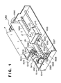
- Fig. 1 is a perspective view showing the outer appearance of an ink-jet printer IJRA as a typical embodiment of the present invention.
- a carriage HC engages with a spiral groove 5004 of a lead screw 5005, which rotates via driving force transmission gears 5009 to 5011 upon forward/reverse rotation of a driving motor 5013.
- the carriage HC has a pin (not shown), and is reciprocally scanned in the directions of arrows a and b in Fig. 1 .
- An integrated ink-jet cartridge IJC which incorporates a printing head IJH and an ink tank IT is mounted on the carriage HC.
- Reference numeral 5002 denotes a sheet pressing plate, which presses a paper sheet against a platen 5000, ranging from one end to the other end of the scanning path of the carriage.
- Reference numerals 5007 and 5008 denote photocouplers which serve as a home position detector for recognizing the presence of a lever 5006 of the carriage in a corresponding region, and used for switching, e.g., the rotating direction of the motor 5013.
- Reference numeral 5016 denotes a member for supporting a cap member 5022, which caps the front surface of the printing head IJH; and 5015, a suction device for sucking ink residue through the interior of the cap member.
- the suction device 5015 performs suction recovery of the printing head via an opening 5023 of the cap member 5015.
- Reference numeral 5017 denotes a cleaning blade; 5019, a member which allows the blade to be movable in the back-and-forth direction of the blade. These members are supported on a main unit support plate 5018. The shape of the blade is not limited to this, but a known cleaning blade can be used in this embodiment.
- Reference numeral 5021 denotes a lever for initiating a suction operation in the suction recovery operation. The lever 5021 moves upon movement of a cam 5020, which engages with the carriage, and receives a driving force from the driving motor via a known transmission mechanism such as clutch switching.
- the capping, cleaning, and suction recovery operations are performed at their corresponding positions upon operation of the lead screw 5005 when the carriage reaches the home-position side region.
- the present invention is not limited to this arrangement as long as desired operations are performed at known timings.
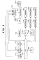
- Fig. 2 is a block diagram showing the arrangement of a control circuit of the ink-jet printer.
- reference numeral 1700 denotes an interface for inputting a printing signal from an external unit such as a host computer; 1701, an MPU; 1702, a ROM for storing a control program executed by the MPU 1701; and 1703, a DRAM for storing various data (the printing signal, printing data supplied to the printing head, and the like).
- Reference numeral 1704 denotes a gate array (G.A.) for performing supply control of printing data to the printing head IJH.
- G.A. gate array
- the gate array 1704 also performs data transfer control among the interface 1700, the MPU 1701, and the RAM 1703.
- Reference numeral 1705 denotes a head driver for driving the printhead IJH; and 1706 and 1707, motor drivers for driving the transfer motor 1709 and the carrier motor 1710.
- the printing signal is converted into printing data for printing operation by the gate array 1704 and the MPU 1701.
- the printhead IJH is driven in accordance with the printing data supplied to the head driver 1705, and performs printing operation.
- a recovery controller 1708 controlled by the MPU 1701, controls various recovery operation such as capping the front surface of the printhead IJH with the cap 5022, cleaning the front surface of the printhead IJH with the cleaning blade 5017, suction recovery of the printhead IJH with the suction device 5015 or the like.
- a dot counter 1712 counts the number of printed dots formed by ink discharged from the printhead IJH during printing operation. The counted number is outputted as a signal to the recovery controller 1708 along with the progress of the printing operation.
- a time counter 1711a times a printing period and outputs the time count result to the recovery controller 1708.
- a time counter 1711b starts timing duration of non-printing state of the ink-jet printing apparatus when the power of the ink-jet printer IJRA is first turned on, and outputs the time count result to the recovery controller 1708. Note that the time counter 1711b is backed up by a battery. Thus, even if the power supply to the ink-jet printer IJRA is off, the time counter 1711b is still operable.
- the recovery controller 1708 transmits a suction operation instruction to the suction device 5015 and MPU 1701, based on the timed results outputted by the time counters 1711a and 1711b and the number of printed dots outputted by the dot counter 1712.
- the ink-jet cartridge IJC may be the exchangeable type that integrally incorporates the ink tank IT and printhead.
- an ink tank IT and printhead IJH may be separately provided so that only the ink tank IT can be exchanged when ink is exhausted.
- Fig. 3 is a perspective view showing the outer appearance of the ink-jet cartridge IJC where the printhead IJH and ink tank IT are separable.
- the ink tank IT is separable from the printhead IJH at the boundary line K as shown in Fig. 3 .
- the ink-jet cartridge IJC includes an electrical contact portion (not shown) so that the ink-jet cartridge IJC receives electrical signals from the carriage HC when mounted on the carriage HC.
- the printhead IJH is driven by the received electrical signals.
- reference numerals 500 denotes a ink discharge orifice array.
- the ink tank IT includes a fibrous or porous ink absorbing member for maintaining ink.
- Fig. 4 is a perspective view of the main part of the printhead IJH which constructs the ink-jet cartridge IJC shown in Fig. 1 .
- a plurality of discharge orifices 1b are formed at predetermined pitch on a discharge orifice surface 1a which faces against the print paper P (see Fig. 1 ) with predetermined spacing.
- reference numeral 4 denotes a substrate comprising electrothermal transducers 1e and an ink supply port 1f which is a long groove-like through hole.
- a row of electrothermal transducers 1e serving as discharge energy generators, are provided, wherein the transducers of two rows are displaced from each other slightly.
- a common ink chamber 1c is connected with each discharge orifice 1b through each liquid path ld.
- the common ink chamber 1c is also connected to the ink tank IT of the ink-jet cartridge IJC so as to receive ink supply from the ink tank IT. Ink supplied from the ink tank IT is temporarily stored in the common ink chamber 1c, then introduced to the liquid path 1d because of capillary phenomenon, and fills the liquid path 1d while forming meniscus at the discharge orifices 1b.
- the first embodiment assumes that there are 256 discharge orifices 1b on the printhead IJH, and that the ink-jet printer IJRA is capable of printing images on paper as large as a size A3 at 1200 DPI with a driving frequency of 10 kHz.
- step S101 it is determined if the power of the ink-jet printer IJRA is turned on for the first time. If it is the first time, the control proceeds to step S102 where the time counter 1711b starts timing the non-printing state period (t2). This timing operation continues even if the power supply to the ink-jet printer IJRA is terminated. Then, the control proceeds to step S103. Meanwhile, if the power of the ink-jet printer IJRA is not turned on for the first time, step S102 is skipped and the control proceeds to step S103.
- step S103 the non-printing state period (t2) timed from the start of the printer IJRA is compared with a threshold value of a non-suction state period (hereinafter referred to as a threshold value t2th).
- a threshold value of a non-suction state period hereinafter referred to as a threshold value t2th.
- the threshold value (t2th) is determined in advance by testing how long a period the ink-jet printer can withstand non-printing state before a printhead causes discharge failure, and the determined threshold value (t2th) is set in the ROM 1702.
- step S116 the control proceeds to step S116 which will be described later.
- step S104 the control proceeds to step S104 for initializing the printing period value (t1) timed by the time counter 1711a. Further, in step S105, the number of printed dots (X) counted by the dot counter 1712 is initialized. Next in step S106, it is determined whether or not printing operation is to be started. If NO, the control returns to step S103, but if YES, the control proceeds to step S107.
- step S107 when the printing operation begins, the time counter 1711a starts timing the printing period (t1). Further in step S108, the dot counter 1712 starts counting the number of printed dots (X). Note that the first embodiment assumes that the time counter 1711a starts timing the printing period (t1) when feeding of printing paper to the ink-jet printer IJRA is completed.
- step S109 it is determined whether or not printing of one sheet of print paper has been completed.
- the control proceeds to step S110 where the time counter 1711a terminates timing of the printing period (t1)
- step S111 the print time duty is calculated according to equation (1).
- a correction coefficient ( ⁇ ) is obtained with reference to Table 1 shown below.
- Correction coefficient ( ⁇ ) is determined in advance based on an experiment. More specifically, correction coefficients ( ⁇ ) for various values (X/t1) calculated by equation (1) are obtained, by changing a print image duty, or by printing a different printing pattern, e.g., a pattern having print data only in the first half of print paper.
- the correction coefficient ( ⁇ ) and a threshold value (Yth) of a corrected print dot count value (Y) which will be described later are determined based on the relation between the number of print dots per unit time and discharge failure as shown in Fig. 10 .
- step S112 the corrected print dot count value (Y) is obtained according to equation (2) by using the correction coefficient ( ⁇ ) as a weight.
- Y Y + X + ⁇ X
- step S113 the corrected print dot count value (Y) is compared with the threshold value (Yth). If Y ⁇ Yth, the control proceeds to step S116. Meanwhile, if Y ⁇ Yth, the control proceeds to step S114 where the non-printing state period (t2) is compared with the threshold value (t2th). Herein, if t2 ⁇ t2th, the control proceeds to step S116. Meanwhile, if t2 ⁇ t2th, the control proceeds to step S115 to determine whether or not to end printing operation. In step S115, if there is no remaining print data, the printing operation is terminated, whereas if unprinted data still remains, the control returns to step S103 for repeating the above-described process until all print data is printed.
- step S116 the recovery controller 1708 transmits a suction operation instruction to the MPU 1701 and suction device 5015.
- the MPU 1701 receives the suction operation instruction in step S116, the MPU 1701 performs control such that the printing operation is halted, and that the carrier motor 1710 is driven to move the carriage HC, carrying the printhead IJH, to the position opposite from the cap 5022 for suction operation.
- the MPU 1701 performs control so that the discharge orifice surface of the printhead IJH is capped by the cap 5022.
- the recovery controller 1708 performs suction operation, in cooperation with the MPU 1701, by operating the suction device 5015.
- step S117 the timed non-printing state period (t2) and corrected print dot count value (Y) are initialized. Then, the control returns to step S115.
- each time printing of one sheet of print paper is completed whether or not suction operation is necessary is determined based on the number of print dots corrected according to the number of print dots per unit time and the non-printing state period. Accordingly, the number of times of suction operation for maintaining the printhead in the most appropriate condition can be kept to the minimum number of times. In addition, reduction in throughput of the ink-jet printer can be minimized, while maintaining the printhead in the most appropriate condition. Furthermore, since the number of times of suction operation is kept minimum, the amount of wasted ink can be kept small, contributing to the reduced amount of ink consumption and reduced operation cost.
- the correction coefficient ( ⁇ ) varies according to the capacity of a common ink chamber of the printhead, the number of discharge nozzles, heat radiation design, or the driving frequency for controlling operation of the printhead. Therefore, the correction coefficient ( ⁇ ) is determined based on the specification of each ink-jet printer. In other words, values of the correction coefficient are not limited to those specified in the first embodiment.
- the first embodiment specifies that the time counter starts timing the printing period (t1) when feeding of printing paper to the ink-jet printer is completed, the present invention is not limited to this.
- the timing operation may be started at other times suitable to the construction of the printing apparatus, e.g., when the carriage HC starts moving in the main scanning direction.
- an ink-jet printer may employ a control method (temperature rise detection) which allows printing only when the temperature of a printhead is lower than a predetermined temperature.
- an ink-jet printer may be controlled such that suction operation is always executed after power is turned on, so as to remove ink which has become viscous or adherent during non-printing state.
- step S109a in Fig. 6 an ink-jet printer may be controlled such that the print time duty (X/t1) is calculated each time the printing of a single printhead scan (i.e., one line) is completed, so that the number of print dots are corrected each time printing of one line is completed.
- the printing period (t1) starts when a carriage carrying a printhead completes printing of one line, and ends when the carriage completes printing of the next line.
- step S112a is added to the flowchart shown in Fig. 6 .
- the time counter 1711b may be eliminated from the control circuit of the ink-jet printer IJRA so as not to time the non-printing state period (t2).
- the processing shown in the flowchart of Fig. 5 may be substituted by the flowchart shown in Fig. 7 , in which processing related to the non-printing state period (t2) is excluded. In other words, in this processing, the timing of suction operation is obtained from the print time duty.
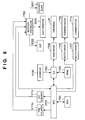
- Fig. 8 is a block diagram showing a construction of a control circuit of the ink-jet printer IJRA. As mentioned above, the construction shown in Fig. 8 differs from that of Fig. 2 only by the excluded time counter 1711a. Thus, for the same components as those shown in Fig. 2 , the same reference numerals are assigned and detailed description thereof is omitted. In other words, the example does not time the printing period (t1).
- Steps S101 to S108 are executed similarly to the first embodiment except for step S104 in Fig. 5 where the time counter 1711a is initialized, and step S107 in Fig. 5 where the Lime counter 1711a starts timing the printing period (t1).
- step S109A it is determined whether or not printing of a single scan of the printhead IJH (i.e., printing of one line) is completed. If YES, the control proceeds to step S110A.
- step S110A a print image duty is calculated according to equation (3).
- Xall is the number of dots printed in a case where printing is performed with 100% print image duty, in other words, the total number of dots which construct the unit printing area (area printed by a single scan of printhead IJH).
- a correction coefficient ( ⁇ ) is obtained by preferring to a table similar to the aforementioned Table 1, which shows relations between various values of print image duty and corresponding correction coefficients ( ⁇ ) .
- the correction coefficient ( ⁇ ) is determined in advance, as similar to the first embodiment, by changing a print image duty, or by printing a different printing pattern, e.g., a pattern having print data only in the first half of print paper.
- steps S112 to S117 are executed as similar to the first embodiment.
- each time printing of a single printhead scan is completed whether or not suction operation is necessary is determined based on the number of print dots per unit printing area, i.e., the number of print dots corrected according to a print image duty, and the non-printing state period. Accordingly, the number of times of suction operation for maintaining the printhead in the most appropriate condition can be kept to the minimum number of times. In addition, reduction in throughput of the ink-jet printer can be minimized, while maintaining the printhead in the most appropriate condition. Furthermore, since the number of times of suction operation is kept minimum, the amount of wasted ink can be kept small, contributing to the reduced amount of ink consumption and reduced operation cost.
- the contents are not limited to ink.
- the ink tank may contain processed liquid or the like which is discharged to a print medium in order to improve the fixation or water repellency of the printed image or to improve the image quality.
- Each of the embodiments and examples described above comprises means (e.g., an electrothermal transducer, laser beam generator, and the like) for generating heat energy as energy utilized upon execution of ink discharge, and adopts the method which causes a change in state of ink by the heat energy, among the ink-jet printing method. According to this printing method, a high-density, high-precision printing operation can be attained.
- means e.g., an electrothermal transducer, laser beam generator, and the like
- the system is effective because, by applying at least one driving signal, which corresponds to printing information and causes a rapid temperature rise exceeding nucleate boiling, to each of electrothermal transducers arranged in correspondence with a sheet or liquid channels holding a liquid (ink), heat energy is generated by the electrothermal transducer to affect film boiling on the heat acting surface of the printhead, and consequently, a bubble can be formed in the liquid (ink) in one-to-one correspondence with the driving signal.
- the driving signal is applied as a pulse signal, the growth and shrinkage of the bubble can be attained instantly and adequately to achieve discharge of the liquid (ink) with particularly high response characteristics.
- signals disclosed in U.S. Patent Nos. 4,463,359 and 4,345,262 are suitable. Note that further excellent printing can be performed by using the conditions of the invention described in U.S. Patent No. 4,313,124 which relates to the temperature rise rate of the heat acting surface.
- the printhead in addition to the arrangement as a combination of discharge nozzles, liquid channels, and electrothermal transducers (linear liquid channels or right angle liquid channels) as disclosed in the above specifications, the arrangement using U.S. Patent Nos. 4,558,333 and 4,459,600 , which disclose the arrangement having a heat acting portion arranged in a flexed region is also included.
- the present invention can be effectively applied to an arrangement based on Japanese Patent Application Laid-Open No.
- 59-123670 which discloses the arrangement using a slot common to a plurality of electrothermal transducers as a discharge portion of the electrothermal transducers, or Japanese Patent Application Laid-Open No- 59-138461 which discloses the arrangement having an opening for absorbing a pressure wave of heat energy in correspondence with a discharge portion.
- a full line type printhead having a length corresponding to the width of a maximum printing medium which can be printed by the printer
- either the arrangement which satisfies the full-line length by combining a plurality of printheads as disclosed in the above specification or the arrangement as a single printhead obtained by forming printheads integrally can be used.
- an exchangeable chip type printhead which can be electrically connected to the apparatus main unit and can receive ink from the apparatus main unit upon being mounted on the apparatus main unit, or a cartridge type printhead in which an ink tank is integrally arranged on the printhead itself, is applicable.
- recovery means for the printhead, preliminary auxiliary means, and the like provided as an arrangement of the printer of the present invention since the printing operation can be further stabilized.
- examples of such means include, for the printhead, capping means, cleaning means, pressurisation or suction means, and preliminary heating means using electrothermal transducers, another heating element, or a combination thereof. It is also effective for stable printing to provide a preliminary discharge mode which performs discharge independent of printing.
- a printing mode of the printer not only a printing mode using only a single color such as black or the like, but also at least one of a multicolor mode using a plurality of different colors or a full-color mode achieved by color mixing can be implemented in the printer either by using an integrated printhead or by combining a plurality of printheads.
- the ink is a liquid.
- ink which is solid at room temperature or less, or ink which softens or liquefies at room temperature, or ink which liquefies upon application of a printing signal may be employed, since it is a genera practice to perform temperature control of the ink itself within a range from 30°C to 70°C in the ink-jet system, so that the ink viscosity can fall within a stable discharge range.
- ink which is solid in a non-use state and liquefies upon heating may be used.
- ink which liquefies upon application of heat energy according to a printing signal and is discharged in a liquid state ink which begins to solidify when it reaches a printing medium, or the like, is applicable to the present invention.
- ink may be situated opposite to electrothermal transducers while being held in a liquid or solid state in recess portions of a porous sheet or through holes, as described in Japanese Patent Application Laid-Open No. 54-56847 or 60-71260 .
- the above-mentioned film boiling system is most effective for the above-mentioned inks.
- the ink-jet printer may be used in the form of a copying machine combined with a reader, and the like, or a facsimile apparatus having a transmission/reception function in addition to an image output terminal of an information processing equipment such as a computer.
- the embodiments and examples can be applied to a system constituted by a plurality of devices (e.g., host. computer, interface, reader, printer) or to an apparatus comprising a single device (e.g., copying machine, facsimile machine).
- a plurality of devices e.g., host. computer, interface, reader, printer
- an apparatus comprising a single device (e.g., copying machine, facsimile machine).
- the described method can also be achieved by providing a storage medium storing program codes for performing the aforesaid processes to a computer system or apparatus (e.g., a personal computer), reading the program codes, by a CPU or MPU of the computer system or apparatus, from the storage medium, then executing the program.
- a computer system or apparatus e.g., a personal computer
- the program codes read from the storage medium realize the functions according to the embodiments and examples.
- the storage medium such as a floppy disk, a hard disk, an optical disk, a magneto-optical disk, CD-ROM, CD-R, a magnetic tape, a non-volatile type memory card, and ROM can be used for providing the program codes.
Abstract
Description
- The present invention relates to a printing apparatus and suction recovery control method, and more particularly, to a printing apparatus employing a printhead which performs printing in accordance with an ink-jet printing method, and suction recovery control method.
- A printing apparatus, employed in a printer or a printer unit of a copy machine or facsimile apparatus or the like, prints an image based on inputted image data by forming dot patterns on a print medium, e.g., paper, thin plastic sheet, fabric or the like.
- Such printing apparatus can be categorized according to printing methods, e.g., ink-jet method, wire dot method, thermal-transfer method, laser-beam method and so on.
- Among these printing apparatuses, the type employing ink-jet printing method which performs printing by discharging ink from a printhead to a print medium is advantageous, not only because printing can be performed with high precision at high speed, but because printing can be performed with low noise by virtue of the non-impact method, and color images can easily be printed with multiple colors of ink.
- Furthermore, according to a bubble-jet method of the ink-jet printing method, ink is heated to cause film boiling and ink is discharged by pressure of bubbles generated by the film boiling. The bubble-jet method is known to realize high resolution printing and high speed printing even more easily.
- An ink-jet printing apparatus, using ink as a recording material for printing, attributes importance to reliability maintenance for the ink discharge function of a printhead, in order to prevent negative influence on printing, caused by ink evaporation or bubble mixture in ink.
- More specifically, while an ink-jet printing apparatus is performing printing operation or is not in use, bubbles are gradually generated inside the ink discharge nozzles of the printhead or in the inserted portion of the printhead. This may disable ink discharge (no discharge) or cause discharge failure, disabling normal print operation. In order to eliminate these bubbles, the ink-jet printing apparatus comprises a cap for capping the printhead, and a head recovery unit having a suction pump for sucking ink inside the cap. The ink discharge surface of the printhead is capped at the position where the printhead faces against the cap, and the suction pump sucks bubbles inside the printhead. The suction recovery processing is an important technique for reliability maintenance of the ink-jet printing apparatus.
- However, even if a suction condition is determined so as to make full use of the bubble-eliminating capability of the head recovery unit, in reality, volumes of bubbles vary in different suction operations. Therefore, the same bubble-eliminating performance cannot always be achieved. In view of this, in order to maintain excellent bubble-eliminating performance, the conventional ink-jet printing apparatus counts the number of times of discharge, or times the non-printing state period of the apparatus, or executes both, so that the suction is performed while the bubble volume is as constant as possible, and then controls suction operation in accordance with the counted values. More specifically, the timing of suction operation of the printhead is determined based on the point of time whichever earlier: at which a predetermined time has elapsed from an initial point of time, or at which a predetermined amount of printing is completed from the initial point of time.
- Japanese Patent Application Laid-Open (KOKAI) No.
6-238914 - However, the reliability maintenance employed in the conventional ink-jet printing apparatus does not consider the number of times of discharge per unit printing area of a printhead (e.g., actual number of times of discharge while an image corresponding to one line is printed on A4-size paper. Hereinafter referred to as a print image duty). Therefore, depending on a print image duty, suction operation is unnecessarily performed, causing to reduce the throughput of the printing apparatus or increase the amount of wasted ink, or causing discharge failure by bubbles before suction operation is performed.
- Particularly, the bubble-jet method employs a method of locally heating ink to cause film boiling to generate ink discharge energy. According to this method, the internal temperature of the printhead gradually rises as printing operation is performed, and as a result of the temperature rise, the generation state or growth rate of bubbles changes. In view of this, as described above, the conventional example proposes a method of determining the timing of suction operation of the printhead based on the number of times of discharge, non-printing state period of the printer, and printhead temperature.
- However, this method has the following problems.
- (1) The temperature rise of a printhead varies for each head.
- (2) Temperature detection accuracy of a printhead varies, making accurate control difficult.
- (3) The internal temperature of a printhead differs depending on a pattern of a printing image.
- Hereinafter, these three problems are described further in detail.
- The following facts have been discovered as a result of careful study of causes and mechanism of bubble generation in a printhead which causes discharge failure.
- In a case where printing operation is performed by a printhead employing an ink-jet printing method, small bubbles are first generated in the printhead, and then these bubbles are coalesced to grow into large bubbles. After the bubbles are first generated, if ink is not discharged from the printhead, these bubbles melt in the ink and disappear. Therefore, it is considered that the condition for small bubbles to coalesce and grow into large bubbles is to repeat ink discharge from the printhead within a predetermined time period before small bubbles disappear. In other words, if the printhead performs many times of ink discharge within a unit time period, bubbles coalesce and grow before disappearing, thus causing discharge failure.
-
Fig. 10 shows a relation between the number of lines printed by a printhead before discharge failure occurs, and a print time duty. Note that the print time duty is the number of print dots per unit time (dot/second). - As can be apparent from
Fig. 10 , as the number of print dots per unit time increases, discharge failure occurs at the smaller number of line, i.e., discharge failure occurs in the earlier stage. - If the internal temperature of the printhead is further taken into consideration, the case where the number of print dots per unit time is large and the internal temperature is low is more likely to cause discharge failure than the case where the number of print dots per unit time is small and the internal temperature is high.
- As described above, mere detection of a printhead temperature is not sufficient for determining suction operation timing. Particularly when an ink-jet printing apparatus is in a print stand-by state during print data transfer, growth of bubbles, i.e., occurrence of discharge failure, is more highly correlated with the number of print dots per unit time than the printhead temperature, as is apparent from the aforementioned study. Furthermore, in a case where an ink-jet printing apparatus executes control (hereinafter referred to as temperature rise detection) such that printing is allowed only when the printhead temperature is lower than a predetermined temperature, discharge failure occurs depending on the print time duty rather than the printhead temperature.
- In other words, mass-produced ink-jet printheads differ in various printing characteristics. Therefore, even in a case where the same print data is inputted to print the same image, consideration must be given in that there may be a printhead which easily raises temperature and a printhead which does not easily raise temperature. Therefore, despite execution of temperature rise detection, the printhead which does not easily raise temperature is more likely to allow printing than the printhead which easily raises temperature. In other words, the printhead which does not easily raise temperature is more likely to perform printing consecutively or perform a number of times of printing within the unit time than the printhead which easily raises temperature.
- Therefore, the printhead which has a low temperature and does not easily raise the temperature, is more likely to cause discharge failure by bubbles in the printhead, than the printhead which has a high temperature and easily raises the temperature. As described above, an ink-jet printing apparatus raises a problem in that the conventional temperature rise detection cannot sufficiently prevent discharge failure because there are cases where discharge failure due to bubbles in the printhead occurs when a printhead has a low temperature rather than a high temperature.
- Furthermore, in the conventional method of determining the timing of suction operation of a printhead based on the number of times of discharge, non-printing state period, and printhead temperature, there is a problem because the precision of a head temperature sensor of the ink-jet printing apparatus is not sufficient.
- More specifically, even if the printhead temperature (detected temperature) detected by the sensor of the printing apparatus is low, there may be cases that the actual printhead temperature is higher than the detected temperature. In this case, suction operation is not performed, causing discharge failure. On the contrary, even if the printhead temperature (detected temperature) detected by the sensor of the printing apparatus is high, there may be cases that the actual printhead temperature is lower than the detected temperature. In this case, the number of times of suction operation may unnecessarily increase, resulting in a reduced throughput of printing operation and the increased amount of wasted ink.
- Furthermore, there may be cases where the timing of suction operation cannot accurately be determined depending on the printing pattern. For instance, as shown in
Fig. 11A , in a case of printing a pattern having a high print image duty in the first half of a print medium and a pattern having a low print image duty in the latter half of the print medium, the printhead temperature detected at the end of printing the pattern on the print medium is relatively low compared to a case of printing a pattern having a uniform print image duty on the entire print medium. Because of this, suction operation is not performed, causing discharge failure. - On the contrary, as shown in
Fig. 11B , in a case of printing a pattern having a low print image duty in the first half of a print medium and a pattern having a high print image duty in the latter half of the print medium, the printhead temperature detected at the end of printing the pattern on the print medium is relatively high compared to a case of printing a pattern having a uniform print image duty on the entire print medium- Because of this, the number of times of suction operation may unnecessarily increase, resulting in a reduced throughput of printing operation and the increased amount of wasted ink. - The above-described problems may be solved by executing suction recovery operation while printing one page of print medium. However, performing suction recovery operation may cause to change the state of ink in a printhead. Therefore, if suction recovery operation is performed during printing of one page of print medium, tonality of an image printed on the print medium may change. For this reason, it is not preferable to execute suction recovery operation during printing of one page ot print medium.
- As summarized, it is extremely difficult to execute appropriate printing control according to the printhead temperature of an ink-jet printing apparatus.
-
EP-A-0 589 581 describes a print rate control technique for power management, and a pen servicing technique for determining appropriate service intervals for plural pen ink-jet printers. The number of drops of ink that are fired from each pen in a printhead are counted and the pen firing rate is calculated such that printer throughput can be controlled to limit time-averaged power and such that pen servicing frequency can be based upon the need for such servicing. -
US-A-5 781 204 describes an ink jet apparatus with a suction recovery device and controller to remove bubbles created in an ink jet head. At periodic intervals, the ambient temperature of the ink jet head is measured and the temperature of the ink jet head is presumed. The number of dots discharged in the period is corrected on the basis of the measured ambient temperature and the presumed temperature of the ink jet head. The control of the suction recovery operation is effected in conformity with the corrected number of dots. -
EP-A-0 694 403 describes a printing apparatus in which the number of ink droplets discharged from a printhead is counted and the counted number is accumulated to the total number of dots printed since a last recovery suction. The total number of dots is compared with a threshold and recovery suction is performed if the threshold has been exceeded. -
EP-A-0 622 202 describes a start-up sequence of nozzle clearing procedures of increasing severity. The sequence is performed as long as some of the nozzles fail to fire ink. -
US-A-5 850 237 describes a printing apparatus in which a purge ink procedure is executed to maintain proper operation of an ink jet head. A time period during printing is determined and the number of print drop commands received by each of a plurality of ink ejectors during the time period. A target value for the number of print drop commands received by each ejector is set and if any of the ink ejectors do not receive the appropriate target number of print commands, then a purge ink procedure is performed. -
US-A-5 638 100 describes an ink jet apparatus with a preliminary ejection mode. A drive controlling means includes a defoaming position means for changing the - 12 - position of a defoaming point arising on each heat generating element when ink is ejected in the preliminary ejection mode. -
JP 08 216437 - According to one aspect of the present invention, there is provided a suction recovery control method as set out in claim 1.
- According to another aspect of the present invention, there is provided a printing apparatus as set out in
claim 11. - Other features and advantages of the present invention will be apparent from the following description taken in conjunction with the accompanying drawings, in which like reference characters designate the same or similar parts throughout the figures thereof.
- The accompanying drawings, which are incorporated in and constitute a part of the specification, illustrate embodiments of the invention, and together with the description, serve to explain the principles of the invention.
-
Fig 1 is a perspective view showing an external appearance of an ink-jet printer IJRA according to a typical embodiment of the present invention; -
Fig. 2 is a block diagram showing a construction of a control circuit of the ink-jet printer IJRA according to the first embodiment; -
Fig. 3 is a perspective view showing an external appearance of an ink cartridge IJC having a separable ink tank and head; -
Fig. 4 is a perspective view of the main part of a printhead IJH, which constructs the ink-jet cartridge IJC shown inFig. 1 ; -
Fig. 5 is a flowchart showing control steps of suction operation according to Lhe first embodiment; -
Fig. 6 is a flowchart showing control steps of suction operation according to a modified example of the first embodiment; -
Fig. 7 is a flowchart showing control steps of suction operation according to another modified example of the first embodiment; -
Fig. 8 is a block diagram showing a construction of a control circuit of the ink-jet printer IJRA according to an example not falling within the scope of the claims; -
Fig. 9 is a flowchart showing control steps of suction operation according to the example not falling within the scope of the claims; -
Fig. 10 shows a relation between the number of lines printed by a printhead before discharge failure occurs, and a print time duty; and -
Figs. 11A and 11B show printing patterns in which a print duty largely changes within one page of print medium. - Preferred embodiments of the present invention and examples not falling within the scope of the claims will be described in detail in accordance with the accompanying drawings.
- According to the embodiments and examples which will be described below, a print image duty is defined as follows. A print image duty is the number of print dots printed by ink discharge within a unit printing area, for example, the actual number of times of ink discharge while a printhead performs printing of a single scan (one line) on A4-size paper. In this case, the value of the print image duty may be expressed by a ratio of the number of printed dots to the total number of dots in the unit printing area.
- Furthermore, the print time duty is obtained by dividing the number of printed dots, formed by ink discharge, by the time period required to print the printed dots. For instance, in a case of printing 10,000 dots by ink discharge, the print time duty is obtained by dividing 10,000 dots by the time period required to print 10,000 dots. Herein, the time period required for printing may be the period from the start of ink discharge to print the first dot until the end of ink discharge to print the 10,000th dot, or may be the timing convenient for the printing apparatus, e.g., the period from the end of paper feed until the start of paper discharge. In any case, the relation between the print image duty and discharge failure with such timing needs to be clarified in advance.
-
Fig. 1 is a perspective view showing the outer appearance of an ink-jet printer IJRA as a typical embodiment of the present invention. Referring toFig. 1 , a carriage HC engages with aspiral groove 5004 of alead screw 5005, which rotates via driving force transmission gears 5009 to 5011 upon forward/reverse rotation of a drivingmotor 5013. The carriage HC has a pin (not shown), and is reciprocally scanned in the directions of arrows a and b inFig. 1 . An integrated ink-jet cartridge IJC which incorporates a printing head IJH and an ink tank IT is mounted on the carriage HC.Reference numeral 5002 denotes a sheet pressing plate, which presses a paper sheet against aplaten 5000, ranging from one end to the other end of the scanning path of the carriage.Reference numerals lever 5006 of the carriage in a corresponding region, and used for switching, e.g., the rotating direction of themotor 5013.Reference numeral 5016 denotes a member for supporting acap member 5022, which caps the front surface of the printing head IJH; and 5015, a suction device for sucking ink residue through the interior of the cap member. Thesuction device 5015 performs suction recovery of the printing head via anopening 5023 of thecap member 5015.Reference numeral 5017 denotes a cleaning blade; 5019, a member which allows the blade to be movable in the back-and-forth direction of the blade. These members are supported on a mainunit support plate 5018. The shape of the blade is not limited to this, but a known cleaning blade can be used in this embodiment.Reference numeral 5021 denotes a lever for initiating a suction operation in the suction recovery operation. Thelever 5021 moves upon movement of acam 5020, which engages with the carriage, and receives a driving force from the driving motor via a known transmission mechanism such as clutch switching. - The capping, cleaning, and suction recovery operations are performed at their corresponding positions upon operation of the
lead screw 5005 when the carriage reaches the home-position side region. However, the present invention is not limited to this arrangement as long as desired operations are performed at known timings. - Next, the control structure necessary to execute printing control of the above-described printing apparatus is described.
Fig. 2 is a block diagram showing the arrangement of a control circuit of the ink-jet printer. Referring toFig. 2 showing the control circuit,reference numeral 1700 denotes an interface for inputting a printing signal from an external unit such as a host computer; 1701, an MPU; 1702, a ROM for storing a control program executed by theMPU 1701; and 1703, a DRAM for storing various data (the printing signal, printing data supplied to the printing head, and the like).Reference numeral 1704 denotes a gate array (G.A.) for performing supply control of printing data to the printing head IJH. Thegate array 1704 also performs data transfer control among theinterface 1700, theMPU 1701, and theRAM 1703.Reference numeral 1705 denotes a head driver for driving the printhead IJH; and 1706 and 1707, motor drivers for driving thetransfer motor 1709 and thecarrier motor 1710. - The operation of the above control arrangement will be described below. When a printing signal is inputted to the
interface 1700, the printing signal is converted into printing data for printing operation by thegate array 1704 and theMPU 1701. As themotor drivers head driver 1705, and performs printing operation. - Furthermore, a
recovery controller 1708, controlled by theMPU 1701, controls various recovery operation such as capping the front surface of the printhead IJH with thecap 5022, cleaning the front surface of the printhead IJH with thecleaning blade 5017, suction recovery of the printhead IJH with thesuction device 5015 or the like. - A
dot counter 1712 counts the number of printed dots formed by ink discharged from the printhead IJH during printing operation. The counted number is outputted as a signal to therecovery controller 1708 along with the progress of the printing operation. - A
time counter 1711a times a printing period and outputs the time count result to therecovery controller 1708. Atime counter 1711b starts timing duration of non-printing state of the ink-jet printing apparatus when the power of the ink-jet printer IJRA is first turned on, and outputs the time count result to therecovery controller 1708. Note that thetime counter 1711b is backed up by a battery. Thus, even if the power supply to the ink-jet printer IJRA is off, thetime counter 1711b is still operable. - The
recovery controller 1708 transmits a suction operation instruction to thesuction device 5015 andMPU 1701, based on the timed results outputted by the time counters 1711a and 1711b and the number of printed dots outputted by thedot counter 1712. - Note that, as described above, the ink-jet cartridge IJC may be the exchangeable type that integrally incorporates the ink tank IT and printhead. Alternatively, an ink tank IT and printhead IJH may be separately provided so that only the ink tank IT can be exchanged when ink is exhausted.
-
Fig. 3 is a perspective view showing the outer appearance of the ink-jet cartridge IJC where the printhead IJH and ink tank IT are separable. The ink tank IT is separable from the printhead IJH at the boundary line K as shown inFig. 3 . The ink-jet cartridge IJC includes an electrical contact portion (not shown) so that the ink-jet cartridge IJC receives electrical signals from the carriage HC when mounted on the carriage HC. The printhead IJH is driven by the received electrical signals. - Note that in
Fig. 3 ,reference numerals 500 denotes a ink discharge orifice array. The ink tank IT includes a fibrous or porous ink absorbing member for maintaining ink. - Next, the aforementioned printhead IJH is described with reference to
Fig. 4 . -
Fig. 4 is a perspective view of the main part of the printhead IJH which constructs the ink-jet cartridge IJC shown inFig. 1 . - As shown in
Fig. 4 , in the printhead IJH, a plurality ofdischarge orifices 1b are formed at predetermined pitch on adischarge orifice surface 1a which faces against the print paper P (seeFig. 1 ) with predetermined spacing. InFig. 4 ,reference numeral 4 denotes a substrate comprisingelectrothermal transducers 1e and anink supply port 1f which is a long groove-like through hole. On each side of the elongatedink supply port 1f, a row ofelectrothermal transducers 1e, serving as discharge energy generators, are provided, wherein the transducers of two rows are displaced from each other slightly. A common ink chamber 1c is connected with eachdischarge orifice 1b through each liquid path ld. - The common ink chamber 1c is also connected to the ink tank IT of the ink-jet cartridge IJC so as to receive ink supply from the ink tank IT. Ink supplied from the ink tank IT is temporarily stored in the common ink chamber 1c, then introduced to the
liquid path 1d because of capillary phenomenon, and fills theliquid path 1d while forming meniscus at thedischarge orifices 1b. - With this state, if the
electrothermal transducers 1e are electrified through electrodes (not shown) to generate heat, ink on theelectrothermal transducers 1e is rapidly heated and bubbles are generated in the liquid path ld. As a result of bubble expansion, ink is discharged from thedischarge orifices 1b. - Note that the first embodiment assumes that there are 256
discharge orifices 1b on the printhead IJH, and that the ink-jet printer IJRA is capable of printing images on paper as large as a size A3 at 1200 DPI with a driving frequency of 10 kHz. - Next, suction operation control of the ink-jet printer IJRA, having the above-described construction, is described with reference to the flowchart in
Fig. 5 . - In step S101, it is determined if the power of the ink-jet printer IJRA is turned on for the first time. If it is the first time, the control proceeds to step S102 where the
time counter 1711b starts timing the non-printing state period (t2). This timing operation continues even if the power supply to the ink-jet printer IJRA is terminated. Then, the control proceeds to step S103. Meanwhile, if the power of the ink-jet printer IJRA is not turned on for the first time, step S102 is skipped and the control proceeds to step S103. - In step S103, the non-printing state period (t2) timed from the start of the printer IJRA is compared with a threshold value of a non-suction state period (hereinafter referred to as a threshold value t2th). Note that the threshold value (t2th) is determined in advance by testing how long a period the ink-jet printer can withstand non-printing state before a printhead causes discharge failure, and the determined threshold value (t2th) is set in the
ROM 1702. - Herein, if t2 ≥ t2th, the control proceeds to step S116 which will be described later.
- If t2 < t2th, the control proceeds to step S104 for initializing the printing period value (t1) timed by the
time counter 1711a. Further, in step S105, the number of printed dots (X) counted by thedot counter 1712 is initialized. Next in step S106, it is determined whether or not printing operation is to be started. If NO, the control returns to step S103, but if YES, the control proceeds to step S107. - In step S107, when the printing operation begins, the
time counter 1711a starts timing the printing period (t1). Further in step S108, thedot counter 1712 starts counting the number of printed dots (X). Note that the first embodiment assumes that thetime counter 1711a starts timing the printing period (t1) when feeding of printing paper to the ink-jet printer IJRA is completed. - Next in step S109, it is determined whether or not printing of one sheet of print paper has been completed. When it is completed, the control proceeds to step S110 where the
time counter 1711a terminates timing of the printing period (t1) Then in step S111, the print time duty is calculated according to equation (1).
- Further in step S111, based on the calculated value (X/t1) of the print time duty, a correction coefficient (α) is obtained with reference to Table 1 shown below. Correction coefficient (α) is determined in advance based on an experiment. More specifically, correction coefficients (α) for various values (X/t1) calculated by equation (1) are obtained, by changing a print image duty, or by printing a different printing pattern, e.g., a pattern having print data only in the first half of print paper. According to the first embodiment, the correction coefficient (α) and a threshold value (Yth) of a corrected print dot count value (Y) which will be described later are determined based on the relation between the number of print dots per unit time and discharge failure as shown in
Fig. 10 .Table 1 X/ t1 α 0 ≤ X/t1 < 200,000 -0.50 200,000 ≤ X/t1 < 400,000 -0.32 400,000 ≤ X/t1 < 600,000 0.00 600,000 ≤ X/t1 < 800,000 1.00 800,000 ≤ X/t1 4.00 - Next in step S112, the corrected print dot count value (Y) is obtained according to equation (2) by using the correction coefficient (α) as a weight.

- In step S113, the corrected print dot count value (Y) is compared with the threshold value (Yth). If Y≥Yth, the control proceeds to step S116. Meanwhile, if Y<Yth, the control proceeds to step S114 where the non-printing state period (t2) is compared with the threshold value (t2th). Herein, if t2≥t2th, the control proceeds to step S116. Meanwhile, if t2<t2th, the control proceeds to step S115 to determine whether or not to end printing operation. In step S115, if there is no remaining print data, the printing operation is terminated, whereas if unprinted data still remains, the control returns to step S103 for repeating the above-described process until all print data is printed.
- In step S116, the
recovery controller 1708 transmits a suction operation instruction to theMPU 1701 andsuction device 5015. When theMPU 1701 receives the suction operation instruction in step S116, theMPU 1701 performs control such that the printing operation is halted, and that thecarrier motor 1710 is driven to move the carriage HC, carrying the printhead IJH, to the position opposite from thecap 5022 for suction operation. Moreover, theMPU 1701 performs control so that the discharge orifice surface of the printhead IJH is capped by thecap 5022. Then, therecovery controller 1708 performs suction operation, in cooperation with theMPU 1701, by operating thesuction device 5015. - Then in step S117, the timed non-printing state period (t2) and corrected print dot count value (Y) are initialized. Then, the control returns to step S115.
- According to the above-described first embodiment, each time printing of one sheet of print paper is completed, whether or not suction operation is necessary is determined based on the number of print dots corrected according to the number of print dots per unit time and the non-printing state period. Accordingly, the number of times of suction operation for maintaining the printhead in the most appropriate condition can be kept to the minimum number of times. In addition, reduction in throughput of the ink-jet printer can be minimized, while maintaining the printhead in the most appropriate condition. Furthermore, since the number of times of suction operation is kept minimum, the amount of wasted ink can be kept small, contributing to the reduced amount of ink consumption and reduced operation cost.
- Note that although the first embodiment employs the correction coefficient (α) shown in Table 1, the correction coefficient (α) varies according to the capacity of a common ink chamber of the printhead, the number of discharge nozzles, heat radiation design, or the driving frequency for controlling operation of the printhead. Therefore, the correction coefficient (α) is determined based on the specification of each ink-jet printer. In other words, values of the correction coefficient are not limited to those specified in the first embodiment.
- Furthermore, although the first embodiment specifies that the time counter starts timing the printing period (t1) when feeding of printing paper to the ink-jet printer is completed, the present invention is not limited to this. The timing operation may be started at other times suitable to the construction of the printing apparatus, e.g., when the carriage HC starts moving in the main scanning direction.
- Furthermore, although description is not provided in the foregoing first embodiment, an ink-jet printer may employ a control method (temperature rise detection) which allows printing only when the temperature of a printhead is lower than a predetermined temperature.
- Still further, although the first embodiment has described a control method of performing suction operation based on a result of comparing respective counter values, the present invention is not limited to this. For instance, an ink-jet printer may be controlled such that suction operation is always executed after power is turned on, so as to remove ink which has become viscous or adherent during non-printing state.
- Furthermore, in the processing explained in the flowchart in
Fig. 5 , although the print time duty (X/t1) is calculated each time one sheet of print paper is printed, the present invention is not limited to this. For instance, as shown in step S109a inFig. 6 , an ink-jet printer may be controlled such that the print time duty (X/t1) is calculated each time the printing of a single printhead scan (i.e., one line) is completed, so that the number of print dots are corrected each time printing of one line is completed. In this case, the printing period (t1) starts when a carriage carrying a printhead completes printing of one line, and ends when the carriage completes printing of the next line. In order to perform such control, step S112a is added to the flowchart shown inFig. 6 . - Note that in the flowchart in
Fig. 6 , processes other than steps S109a and S112a are the same as those shown inFig. 5 . Therefore, for the same processing, the same step reference numerals are assigned and detailed description thereof is omitted. - Moreover, if bubbles do not largely grow in a printhead in the non-printing state, the
time counter 1711b may be eliminated from the control circuit of the ink-jet printer IJRA so as not to time the non-printing state period (t2). In this case, the processing shown in the flowchart ofFig. 5 may be substituted by the flowchart shown inFig. 7 , in which processing related to the non-printing state period (t2) is excluded. In other words, in this processing, the timing of suction operation is obtained from the print time duty. - Hereinafter, an example using a controls circuit which employs only one time counter is described, in comparison with the construction of the control circuit of the ink-jet printer according to the first embodiment.
-
Fig. 8 is a block diagram showing a construction of a control circuit of the ink-jet printer IJRA. As mentioned above, the construction shown inFig. 8 differs from that ofFig. 2 only by the excludedtime counter 1711a. Thus, for the same components as those shown inFig. 2 , the same reference numerals are assigned and detailed description thereof is omitted. In other words, the example does not time the printing period (t1). - Next, suction operation controls according to the example is described-with reference to the flowchart shown in
Fig. 9 . Note that the flowchart inFig. 9 includes processing steps common to those in the flowchart shown inFig. 5 . Therefore, for the common processing steps, the same step reference numerals are assigned and detailed description thereof is omitted. Hereinafter, description will be provided only for the processing steps characteristic to the example, - Steps S101 to S108 are executed similarly to the first embodiment except for step S104 in
Fig. 5 where thetime counter 1711a is initialized, and step S107 inFig. 5 where theLime counter 1711a starts timing the printing period (t1). - Then, in step S109A, it is determined whether or not printing of a single scan of the printhead IJH (i.e., printing of one line) is completed. If YES, the control proceeds to step S110A.
- In step S110A, a print image duty is calculated according to equation (3).

- Herein, Xall is the number of dots printed in a case where printing is performed with 100% print image duty, in other words, the total number of dots which construct the unit printing area (area printed by a single scan of printhead IJH).
- Next in step S111A, a correction coefficient (α) is obtained by preferring to a table similar to the aforementioned Table 1, which shows relations between various values of print image duty and corresponding correction coefficients (α) . The correction coefficient (α) is determined in advance, as similar to the first embodiment, by changing a print image duty, or by printing a different printing pattern, e.g., a pattern having print data only in the first half of print paper.
- Then, steps S112 to S117 are executed as similar to the first embodiment.
- According to the above-described example,
each time printing of a single printhead scan is completed, whether or not suction operation is necessary is determined based on the number of print dots per unit printing area, i.e., the number of print dots corrected according to a print image duty, and the non-printing state period. Accordingly, the number of times of suction operation for maintaining the printhead in the most appropriate condition can be kept to the minimum number of times. In addition, reduction in throughput of the ink-jet printer can be minimized, while maintaining the printhead in the most appropriate condition. Furthermore, since the number of times of suction operation is kept minimum, the amount of wasted ink can be kept small, contributing to the reduced amount of ink consumption and reduced operation cost. - However, in a case where an operation stand-by state occurs due to image data transfer or a print stand-by state is caused by temperature rise detection or the like, it is preferable to correct the number of print dots according to the print time duty.
- Note that in the foregoing embodiments, and examples although the description has been provided based on the assumption that a droplet discharged by the printhead is ink and that the liquid contained in the ink tank is ink, the contents are not limited to ink. For instance, the ink tank may contain processed liquid or the like which is discharged to a print medium in order to improve the fixation or water repellency of the printed image or to improve the image quality.
- Each of the embodiments and examples described above comprises means (e.g., an electrothermal transducer, laser beam generator, and the like) for generating heat energy as energy utilized upon execution of ink discharge, and adopts the method which causes a change in state of ink by the heat energy, among the ink-jet printing method. According to this printing method, a high-density, high-precision printing operation can be attained.
- As the typical arrangement and principle of the ink-jet printing system, one practiced by use of the basic principle disclosed in, for example,
U.S. Patent Nos. 4,723,129 and4,740,796 is preferable. The above system is applicable to either one of so-called on-demand type and continuous type. Particularly, in the case of the on-demand type, the system is effective because, by applying at least one driving signal, which corresponds to printing information and causes a rapid temperature rise exceeding nucleate boiling, to each of electrothermal transducers arranged in correspondence with a sheet or liquid channels holding a liquid (ink), heat energy is generated by the electrothermal transducer to affect film boiling on the heat acting surface of the printhead, and consequently, a bubble can be formed in the liquid (ink) in one-to-one correspondence with the driving signal. By discharging the liquid (ink) through a discharge opening by growth and shrinkage of the bubble, at least one droplet is formed. If the driving signal is applied as a pulse signal, the growth and shrinkage of the bubble can be attained instantly and adequately to achieve discharge of the liquid (ink) with particularly high response characteristics. - As the pulse-form driving signal, signals disclosed in
U.S. Patent Nos. 4,463,359 and4,345,262 are suitable. Note that further excellent printing can be performed by using the conditions of the invention described inU.S. Patent No. 4,313,124 which relates to the temperature rise rate of the heat acting surface. - As an arrangement of the printhead, in addition to the arrangement as a combination of discharge nozzles, liquid channels, and electrothermal transducers (linear liquid channels or right angle liquid channels) as disclosed in the above specifications, the arrangement using
U.S. Patent Nos. 4,558,333 and4,459,600 , which disclose the arrangement having a heat acting portion arranged in a flexed region is also included. In addition, the present invention can be effectively applied to an arrangement based on Japanese Patent Application Laid-Open No.59-123670 59-138461 - Furthermore, as a full line type printhead having a length corresponding to the width of a maximum printing medium which can be printed by the printer, either the arrangement which satisfies the full-line length by combining a plurality of printheads as disclosed in the above specification or the arrangement as a single printhead obtained by forming printheads integrally can be used.
- In addition, an exchangeable chip type printhead which can be electrically connected to the apparatus main unit and can receive ink from the apparatus main unit upon being mounted on the apparatus main unit, or a cartridge type printhead in which an ink tank is integrally arranged on the printhead itself, is applicable.
- It is preferable to add recovery means for the printhead, preliminary auxiliary means, and the like provided as an arrangement of the printer of the present invention since the printing operation can be further stabilized. Examples of such means include, for the printhead, capping means, cleaning means, pressurisation or suction means, and preliminary heating means using electrothermal transducers, another heating element, or a combination thereof. It is also effective for stable printing to provide a preliminary discharge mode which performs discharge independent of printing.
- Furthermore, as a printing mode of the printer, not only a printing mode using only a single color such as black or the like, but also at least one of a multicolor mode using a plurality of different colors or a full-color mode achieved by color mixing can be implemented in the printer either by using an integrated printhead or by combining a plurality of printheads.
- Moreover, in each of the above-mentioned embodiments and examples , it is assumed that the ink is a liquid. Alternatively, ink which is solid at room temperature or less, or ink which softens or liquefies at room temperature, or ink which liquefies upon application of a printing signal may be employed, since it is a genera practice to perform temperature control of the ink itself within a range from 30°C to 70°C in the ink-jet system, so that the ink viscosity can fall within a stable discharge range.
- In addition, in order to prevent a temperature rise caused by heat energy by positively utilizing it as energy for causing a change in state of the ink from a solid state to a liquid state, or to prevent evaporation of the ink, ink which is solid in a non-use state and liquefies upon heating may be used. In any case, ink which liquefies upon application of heat energy according to a printing signal and is discharged in a liquid state, ink which begins to solidify when it reaches a printing medium, or the like, is applicable to the present invention. In this case, ink may be situated opposite to electrothermal transducers while being held in a liquid or solid state in recess portions of a porous sheet or through holes, as described in Japanese Patent Application Laid-Open No.
54-56847 60-71260 - In addition, the ink-jet printer may be used in the form of a copying machine combined with a reader, and the like, or a facsimile apparatus having a transmission/reception function in addition to an image output terminal of an information processing equipment such as a computer.
- The embodiments and examples can be applied to a system constituted by a plurality of devices (e.g., host. computer, interface, reader, printer) or to an apparatus comprising a single device (e.g., copying machine, facsimile machine).
- Further, the described method can also be achieved by providing a storage medium storing program codes for performing the aforesaid processes to a computer system or apparatus (e.g., a personal computer), reading the program codes, by a CPU or MPU of the computer system or apparatus, from the storage medium, then executing the program.
- In this case, the program codes read from the storage medium realize the functions according to the embodiments and examples.
- Further, the storage medium, such as a floppy disk, a hard disk, an optical disk, a magneto-optical disk, CD-ROM, CD-R, a magnetic tape, a non-volatile type memory card, and ROM can be used for providing the program codes.
- Furthermore, besides a foresaid functions according to the above embodiments and examples are realized by executing the program codes which are read by a computer, this includes a case where an OS (operating system) or the like working on the computer performs a part or the entire processes in accordance with designations of the program codes and realizes functions according to the above embodiments and examples. Furthermore, also included is a case where, after the program codes read from the storage medium are written in a function expansion card which is inserted into the computer or in a memory provided in a function expansion unit which is connected to the computer, CPU or the like contained in the function expansion card or unit performs a part or the entire process in accordance with designations of the program codes and realizes functions of the above embodiments and examples .
Claims (15)
- A suction recovery control method of controlling suction recovery operation of a printhead used in an ink-jet printing apparatus, comprising:a first timing step (S107) of timing a printing period (t1) of a predetermined printing operation;a counting step (S108) of counting a number of print dots (X) formed by discharging ink from the printhead during the predetermined printing operation;characterized by:a calculating step (S111) of calculating a number (X/t1) of print dots per unit time based on the printing period (t1) timed in said first timing step (S107) and the number of print dots (X) counted by said counting step (S108);a correction step (S112) of correcting the counted number (X) of print dots based on the calculated number of print dots (Y) per unit time;a first comparing step (S113) of comparing the number of print dots (Y), corrected in said correction step, with a predetermined threshold value (Yth) each time printing of one page of print medium is completed; anda determining step of determining (S114) whether or not to perform the suction recovery operation according to a comparison result of said first comparing step; anda control step (S116) of controlling the suction recovery operation of the printhead at the timing decision in said determining step (S114).
- The method according to claim 1, wherein said correction step includes obtaining a correction coefficient (α) from a table of correction coefficients for different ranges of number of print dots per unit time (X/t1).
- The method according to claim 1, further comprising a second timing step of timing a cumulative time period, starting from when power to the ink-jet printing apparatus is first turned on.
- The method according to claim 2, wherein said control step includes a second comparing step (S114) of comparing the cumulative time period (t2) with a predetermined threshold value (t2th) each time the printing of one page of print medium is completed, wherein in said determining step timing of suction recovery operation is determined according to a comparison result of said second comparing step (S114).
- The method according to claim 1, wherein the predetermined printing operation corresponds to performing printing of one page of print medium or performing printing of one scan of the printhead.
- The method according to claim 2, wherein the predetermined threshold value (Yth) employed in said first comparing step is obtained by experimentally counting, in advance, a number of print dots formed before the printhead results in ink discharge failure
- The method according to claim 3, wherein the predetermined threshold value employed in said second comparing step is obtained by experimentally counting, in advance, a number of print dots (X) formed before the printhead results in ink discharge failure.
- The method according to claim 3, wherein in said determining step, the timing of suction recovery operation is the earliest point of time at which the number of print dots (X), corrected in said correction step (S112), exceeds the predetermined threshold value (Yth) in said first comparing step (S113); or
at which the cumulative time period (t2) exceeds the predetermined threshold value (t2th) in said second comparing step (S114). - The method according to claim 1, wherein the printhead comprises electrothermal transducers (1e) for generating heat energy to be applied to ink so as to discharge ink by utilizing the heat energy.
- The method according to claim 7, wherein the printhead discharges ink from discharge orifices (1 b) by utilizing film boiling in the ink, which is generated by heat energy applied by the electrothermal transducers (1e).
- A printing apparatus for printing on a print medium by using an ink-jet printhead, comprising:suction recovery means (5015) for performing suction recovery operation of the ink-jet printhead;first timing means (1711 a) for timing a printing period (t1) of a predetermined printing operation;counting means (1712) for counting a number of print dots (X) formed by discharging ink from the ink-jet printhead during the predetermined printing operation; characterized in that there is providedcalculation means for calculating a number (X/t1) of print dots per unit time based on the printing period (t1) timed by said first timing means and the number of print dots (X) counted by said counting means;correction means of correcting the counted number (X) of print dots based on the calculated number of print dots (Y) per unit time;comparing means for comparing the number of print dots (Y), corrected in said correction step, with a predetermined threshold value (Yth) each time printing of one page of print medium is completed; anda determining means for determining whether or not to perform the suction recovery operation according to a comparison result from said first comparing means; andcontrol means for controlling the suction recovery operation at the timing decided by said determining means.
- The apparatus of claim 11, wherein the comparing means is arranged to obtain a correction coefficient (α) from a table of correction coefficients for different ranges of number of print dots per unit time (X/t1).
- The apparatus according to claim 11, further comprising second timing means (1711 b) for timing a cumulative time period, starting from when power to the printing apparatus is first turned on,
wherein said decision means is arranged to decide the timing of the suction recovery operation while further considering the cumulative time period. - The apparatus according to claim 11, wherein the printhead comprises electrothermal transducers (1e) for generating heat energy to be applied to ink so as to discharge ink by utilizing the heat energy.
- The apparatus according to claim 11, wherein said printhead is arranged to discharge ink from discharge orifices (1 b) utilizing film boiling in the ink, which is generated by heat energy applied by the electrothermal transducers (1e).
Applications Claiming Priority (2)
| Application Number | Priority Date | Filing Date | Title |
|---|---|---|---|
| JP04715599A JP3884878B2 (en) | 1999-02-24 | 1999-02-24 | Recording apparatus and suction recovery control method |
| JP4715599 | 1999-02-24 |
Publications (3)
| Publication Number | Publication Date |
|---|---|
| EP1031425A2 EP1031425A2 (en) | 2000-08-30 |
| EP1031425A3 EP1031425A3 (en) | 2003-01-29 |
| EP1031425B1 true EP1031425B1 (en) | 2010-04-21 |
Family
ID=12767208
Family Applications (1)
| Application Number | Title | Priority Date | Filing Date |
|---|---|---|---|
| EP00301421A Expired - Lifetime EP1031425B1 (en) | 1999-02-24 | 2000-02-23 | Printing apparatus and suction recovery control method |
Country Status (5)
| Country | Link |
|---|---|
| US (2) | US6557969B1 (en) |
| EP (1) | EP1031425B1 (en) |
| JP (1) | JP3884878B2 (en) |
| AT (1) | ATE465009T1 (en) |
| DE (1) | DE60044222D1 (en) |
Families Citing this family (17)
| Publication number | Priority date | Publication date | Assignee | Title |
|---|---|---|---|---|
| JP4646419B2 (en) | 2001-02-23 | 2011-03-09 | キヤノン株式会社 | Ink jet recording apparatus and control method of ink jet recording apparatus |
| AUPR399501A0 (en) * | 2001-03-27 | 2001-04-26 | Silverbrook Research Pty. Ltd. | An apparatus and method(ART107) |
| JP4590150B2 (en) | 2002-08-30 | 2010-12-01 | キヤノン株式会社 | Inkjet recording apparatus and recovery control method |
| JP2004114650A (en) * | 2002-09-30 | 2004-04-15 | Canon Finetech Inc | Recorder |
| JP2005219419A (en) * | 2004-02-06 | 2005-08-18 | Canon Inc | Inkjet recording device |
| JP4717475B2 (en) * | 2005-03-04 | 2011-07-06 | キヤノン株式会社 | Inkjet recording device |
| KR100727968B1 (en) * | 2005-08-24 | 2007-06-13 | 삼성전자주식회사 | Dot counting method and apparatus |
| TWI256915B (en) * | 2005-09-05 | 2006-06-21 | Benq Corp | Method and circuit for controlling an ink-jetting printer |
| JP5145748B2 (en) * | 2007-03-30 | 2013-02-20 | セイコーエプソン株式会社 | Liquid ejection device and recovery operation control method |
| JP5009201B2 (en) * | 2008-03-12 | 2012-08-22 | 株式会社リコー | Image forming apparatus, image forming method, and image forming program |
| JP5721450B2 (en) | 2011-01-26 | 2015-05-20 | キヤノン株式会社 | Ink jet recording apparatus control method and ink jet recording apparatus |
| JP6041481B2 (en) * | 2011-11-30 | 2016-12-07 | キヤノン株式会社 | Ink jet recording apparatus and nozzle recovery method |
| JP2013230606A (en) | 2012-04-27 | 2013-11-14 | Canon Inc | Recording apparatus and color measuring method for recording apparatus |
| JP6045191B2 (en) | 2012-05-21 | 2016-12-14 | キヤノン株式会社 | Ink jet recording apparatus and recording method |
| JP6157131B2 (en) | 2013-02-01 | 2017-07-05 | キヤノン株式会社 | Recording apparatus and cleaning method thereof |
| JP6192439B2 (en) | 2013-08-28 | 2017-09-06 | キヤノン株式会社 | Recording apparatus and control method |
| JP2022098780A (en) * | 2020-12-22 | 2022-07-04 | セイコーエプソン株式会社 | Liquid discharge device, and maintenance method for liquid discharge device |
Family Cites Families (20)
| Publication number | Priority date | Publication date | Assignee | Title |
|---|---|---|---|---|
| CA1127227A (en) | 1977-10-03 | 1982-07-06 | Ichiro Endo | Liquid jet recording process and apparatus therefor |
| US4330787A (en) | 1978-10-31 | 1982-05-18 | Canon Kabushiki Kaisha | Liquid jet recording device |
| US4345262A (en) | 1979-02-19 | 1982-08-17 | Canon Kabushiki Kaisha | Ink jet recording method |
| US4463359A (en) | 1979-04-02 | 1984-07-31 | Canon Kabushiki Kaisha | Droplet generating method and apparatus thereof |
| US4313124A (en) | 1979-05-18 | 1982-01-26 | Canon Kabushiki Kaisha | Liquid jet recording process and liquid jet recording head |
| US4558333A (en) | 1981-07-09 | 1985-12-10 | Canon Kabushiki Kaisha | Liquid jet recording head |
| JPS59123670A (en) | 1982-12-28 | 1984-07-17 | Canon Inc | Ink jet head |
| JPS59138461A (en) | 1983-01-28 | 1984-08-08 | Canon Inc | Liquid jet recording apparatus |
| DE69315159T2 (en) | 1992-09-25 | 1998-03-12 | Hewlett Packard Co | Method and device for controlling a color jet printer by means of drop counting |
| DE69310488T2 (en) | 1992-12-28 | 1997-12-04 | Canon Kk | Ink jet recording apparatus and recovery method therefor |
| JPH06238914A (en) | 1993-02-12 | 1994-08-30 | Canon Inc | Suction operation controlling method of ink-jet recording device and ink-jet recording device |
| US5455608A (en) * | 1993-04-30 | 1995-10-03 | Hewlett-Packard Company | Pen start up algorithm for black and color thermal ink-jet pens |
| EP0639023B1 (en) * | 1993-08-13 | 1997-06-04 | Agfa-Gevaert N.V. | Method for producing frequency-modulated halftone images |
| US5638100A (en) * | 1994-07-29 | 1997-06-10 | Canon Kabushiki Kaisha | Ink jet and ink preliminary ejecting method |
| US6382764B1 (en) | 1994-07-29 | 2002-05-07 | Canon Kabushiki Kaisha | Printing method and apparatus for counting number of ejected ink droplets for controlling printhead recovery |
| JP3376112B2 (en) * | 1994-07-29 | 2003-02-10 | キヤノン株式会社 | Ink jet apparatus and recovery control method therefor |
| JP3311186B2 (en) | 1995-02-14 | 2002-08-05 | キヤノン株式会社 | Recording apparatus and driving method in the apparatus |
| US5850237A (en) * | 1996-06-26 | 1998-12-15 | Xerox Corporation | Method and device for selective recording head maintenance for an ink recording apparatus |
| JPH10226088A (en) * | 1997-02-14 | 1998-08-25 | Canon Inc | Ink jet recording apparatus and processing method for recovery of jet for recording head |
| JP3667117B2 (en) | 1998-10-27 | 2005-07-06 | キヤノン株式会社 | Ink jet recording apparatus and ejection recovery method in the apparatus |
-
1999
- 1999-02-24 JP JP04715599A patent/JP3884878B2/en not_active Expired - Fee Related
-
2000
- 2000-02-23 DE DE60044222T patent/DE60044222D1/en not_active Expired - Lifetime
- 2000-02-23 US US09/511,360 patent/US6557969B1/en not_active Expired - Fee Related
- 2000-02-23 EP EP00301421A patent/EP1031425B1/en not_active Expired - Lifetime
- 2000-02-23 AT AT00301421T patent/ATE465009T1/en not_active IP Right Cessation
-
2003
- 2003-01-27 US US10/351,417 patent/US6752485B2/en not_active Expired - Lifetime
Also Published As
| Publication number | Publication date |
|---|---|
| US6557969B1 (en) | 2003-05-06 |
| EP1031425A2 (en) | 2000-08-30 |
| JP3884878B2 (en) | 2007-02-21 |
| US6752485B2 (en) | 2004-06-22 |
| US20030132983A1 (en) | 2003-07-17 |
| EP1031425A3 (en) | 2003-01-29 |
| JP2000238297A (en) | 2000-09-05 |
| ATE465009T1 (en) | 2010-05-15 |
| DE60044222D1 (en) | 2010-06-02 |
Similar Documents
| Publication | Publication Date | Title |
|---|---|---|
| EP1031425B1 (en) | Printing apparatus and suction recovery control method | |
| US7506953B2 (en) | Ink-jet printing apparatus and preliminary discharge control method for the apparatus | |
| US6352327B1 (en) | Printing apparatus and print control method | |
| EP0595658A2 (en) | Ink jet recording apparatus | |
| EP0864424B1 (en) | Ink jet recording apparatus and method for controlling an amount of ink discharged after an inperruption in recording | |
| US6382764B1 (en) | Printing method and apparatus for counting number of ejected ink droplets for controlling printhead recovery | |
| US6629789B2 (en) | Printing apparatus, driving condition setting method for printhead, and storage medium | |
| US6382765B1 (en) | Ink-jet printing apparatus and discharge recovery method therefor | |
| US6655772B2 (en) | Printing apparatus and printhead temperature management method | |
| EP0576285B1 (en) | Ink jet recording method and apparatus | |
| US6554396B1 (en) | Ink-jet printing apparatus and method | |
| JPH09207358A (en) | Ink jet recording method and device therefor | |
| US6406112B1 (en) | Ink jet recording apparatus, recording control method, and storage medium with recording control program stored therein | |
| US6644777B2 (en) | Liquid ejecting apparatus, and method for maintaining and recovering ejection performance of the same | |
| JP4780882B2 (en) | Inkjet recording apparatus and inkjet recording method | |
| JP4018436B2 (en) | Image recording apparatus and control method thereof | |
| JP2006289624A (en) | Recorder and control method of recorder | |
| JPH07246718A (en) | Printing device and printing | |
| JPH07101077A (en) | Recording device | |
| JP2002331647A (en) | Recorder and recording control method | |
| JPH0776088A (en) | Ink jet recording method and apparatus and data processing device | |
| JP2001199054A (en) | Driving circuit for ink jet recording head, recorder having the same and method of driving ink jet recording head | |
| JP2001341329A (en) | Liquid ejecting device and ejection performance maintaining recovery method for the device | |
| JP2000309110A (en) | Ink jet recorder and method for controlling motor of the recorder |
Legal Events
| Date | Code | Title | Description |
|---|---|---|---|
| PUAI | Public reference made under article 153(3) epc to a published international application that has entered the european phase |
Free format text: ORIGINAL CODE: 0009012 |
|
| AK | Designated contracting states |
Kind code of ref document: A2 Designated state(s): AT BE CH CY DE DK ES FI FR GB GR IE IT LI LU MC NL PT SE |
|
| AX | Request for extension of the european patent |
Free format text: AL;LT;LV;MK;RO;SI |
|
| PUAL | Search report despatched |
Free format text: ORIGINAL CODE: 0009013 |
|
| AK | Designated contracting states |
Designated state(s): AT BE CH CY DE DK ES FI FR GB GR IE IT LI LU MC NL PT SE |
|
| AX | Request for extension of the european patent |
Extension state: AL LT LV MK RO SI |
|
| 17P | Request for examination filed |
Effective date: 20030612 |
|
| AKX | Designation fees paid |
Designated state(s): AT BE CH CY DE DK ES FI FR GB GR IE IT LI LU MC NL PT SE |
|
| 17Q | First examination report despatched |
Effective date: 20040128 |
|
| GRAP | Despatch of communication of intention to grant a patent |
Free format text: ORIGINAL CODE: EPIDOSNIGR1 |
|
| GRAS | Grant fee paid |
Free format text: ORIGINAL CODE: EPIDOSNIGR3 |
|
| GRAA | (expected) grant |
Free format text: ORIGINAL CODE: 0009210 |
|
| AK | Designated contracting states |
Kind code of ref document: B1 Designated state(s): AT BE CH CY DE DK ES FI FR GB GR IE IT LI LU MC NL PT SE |
|
| REG | Reference to a national code |
Ref country code: GB Ref legal event code: FG4D |
|
| REG | Reference to a national code |
Ref country code: CH Ref legal event code: EP |
|
| REG | Reference to a national code |
Ref country code: IE Ref legal event code: FG4D |
|
| REF | Corresponds to: |
Ref document number: 60044222 Country of ref document: DE Date of ref document: 20100602 Kind code of ref document: P |
|
| REG | Reference to a national code |
Ref country code: NL Ref legal event code: VDEP Effective date: 20100421 |
|
| PG25 | Lapsed in a contracting state [announced via postgrant information from national office to epo] |
Ref country code: ES Free format text: LAPSE BECAUSE OF FAILURE TO SUBMIT A TRANSLATION OF THE DESCRIPTION OR TO PAY THE FEE WITHIN THE PRESCRIBED TIME-LIMIT Effective date: 20100801 Ref country code: SE Free format text: LAPSE BECAUSE OF FAILURE TO SUBMIT A TRANSLATION OF THE DESCRIPTION OR TO PAY THE FEE WITHIN THE PRESCRIBED TIME-LIMIT Effective date: 20100421 Ref country code: NL Free format text: LAPSE BECAUSE OF FAILURE TO SUBMIT A TRANSLATION OF THE DESCRIPTION OR TO PAY THE FEE WITHIN THE PRESCRIBED TIME-LIMIT Effective date: 20100421 |
|
| PG25 | Lapsed in a contracting state [announced via postgrant information from national office to epo] |
Ref country code: FI Free format text: LAPSE BECAUSE OF FAILURE TO SUBMIT A TRANSLATION OF THE DESCRIPTION OR TO PAY THE FEE WITHIN THE PRESCRIBED TIME-LIMIT Effective date: 20100421 Ref country code: AT Free format text: LAPSE BECAUSE OF FAILURE TO SUBMIT A TRANSLATION OF THE DESCRIPTION OR TO PAY THE FEE WITHIN THE PRESCRIBED TIME-LIMIT Effective date: 20100421 |
|
| PG25 | Lapsed in a contracting state [announced via postgrant information from national office to epo] |
Ref country code: CY Free format text: LAPSE BECAUSE OF NON-PAYMENT OF DUE FEES Effective date: 20100421 Ref country code: GR Free format text: LAPSE BECAUSE OF FAILURE TO SUBMIT A TRANSLATION OF THE DESCRIPTION OR TO PAY THE FEE WITHIN THE PRESCRIBED TIME-LIMIT Effective date: 20100722 |
|
| PG25 | Lapsed in a contracting state [announced via postgrant information from national office to epo] |
Ref country code: PT Free format text: LAPSE BECAUSE OF FAILURE TO SUBMIT A TRANSLATION OF THE DESCRIPTION OR TO PAY THE FEE WITHIN THE PRESCRIBED TIME-LIMIT Effective date: 20100823 Ref country code: DK Free format text: LAPSE BECAUSE OF FAILURE TO SUBMIT A TRANSLATION OF THE DESCRIPTION OR TO PAY THE FEE WITHIN THE PRESCRIBED TIME-LIMIT Effective date: 20100421 |
|
| PLBE | No opposition filed within time limit |
Free format text: ORIGINAL CODE: 0009261 |
|
| STAA | Information on the status of an ep patent application or granted ep patent |
Free format text: STATUS: NO OPPOSITION FILED WITHIN TIME LIMIT |
|
| PG25 | Lapsed in a contracting state [announced via postgrant information from national office to epo] |
Ref country code: BE Free format text: LAPSE BECAUSE OF FAILURE TO SUBMIT A TRANSLATION OF THE DESCRIPTION OR TO PAY THE FEE WITHIN THE PRESCRIBED TIME-LIMIT Effective date: 20100421 |
|
| 26N | No opposition filed |
Effective date: 20110124 |
|
| PG25 | Lapsed in a contracting state [announced via postgrant information from national office to epo] |
Ref country code: IT Free format text: LAPSE BECAUSE OF FAILURE TO SUBMIT A TRANSLATION OF THE DESCRIPTION OR TO PAY THE FEE WITHIN THE PRESCRIBED TIME-LIMIT Effective date: 20100421 |
|
| PG25 | Lapsed in a contracting state [announced via postgrant information from national office to epo] |
Ref country code: MC Free format text: LAPSE BECAUSE OF NON-PAYMENT OF DUE FEES Effective date: 20110228 |
|
| REG | Reference to a national code |
Ref country code: CH Ref legal event code: PL |
|
| PG25 | Lapsed in a contracting state [announced via postgrant information from national office to epo] |
Ref country code: CH Free format text: LAPSE BECAUSE OF NON-PAYMENT OF DUE FEES Effective date: 20110228 Ref country code: LI Free format text: LAPSE BECAUSE OF NON-PAYMENT OF DUE FEES Effective date: 20110228 |
|
| REG | Reference to a national code |
Ref country code: FR Ref legal event code: ST Effective date: 20111102 |
|
| REG | Reference to a national code |
Ref country code: IE Ref legal event code: MM4A |
|
| PG25 | Lapsed in a contracting state [announced via postgrant information from national office to epo] |
Ref country code: IE Free format text: LAPSE BECAUSE OF NON-PAYMENT OF DUE FEES Effective date: 20110223 Ref country code: FR Free format text: LAPSE BECAUSE OF NON-PAYMENT OF DUE FEES Effective date: 20110228 |
|
| PG25 | Lapsed in a contracting state [announced via postgrant information from national office to epo] |
Ref country code: LU Free format text: LAPSE BECAUSE OF NON-PAYMENT OF DUE FEES Effective date: 20110223 |
|
| PGFP | Annual fee paid to national office [announced via postgrant information from national office to epo] |
Ref country code: DE Payment date: 20170228 Year of fee payment: 18 |
|
| PGFP | Annual fee paid to national office [announced via postgrant information from national office to epo] |
Ref country code: GB Payment date: 20170227 Year of fee payment: 18 |
|
| REG | Reference to a national code |
Ref country code: DE Ref legal event code: R119 Ref document number: 60044222 Country of ref document: DE |
|
| GBPC | Gb: european patent ceased through non-payment of renewal fee |
Effective date: 20180223 |
|
| PG25 | Lapsed in a contracting state [announced via postgrant information from national office to epo] |
Ref country code: DE Free format text: LAPSE BECAUSE OF NON-PAYMENT OF DUE FEES Effective date: 20180901 |
|
| PG25 | Lapsed in a contracting state [announced via postgrant information from national office to epo] |
Ref country code: GB Free format text: LAPSE BECAUSE OF NON-PAYMENT OF DUE FEES Effective date: 20180223 |