EP1031334A2 - Low-profile ostomy faceplate with recessed coupling ring - Google Patents
Low-profile ostomy faceplate with recessed coupling ring Download PDFInfo
- Publication number
- EP1031334A2 EP1031334A2 EP00300143A EP00300143A EP1031334A2 EP 1031334 A2 EP1031334 A2 EP 1031334A2 EP 00300143 A EP00300143 A EP 00300143A EP 00300143 A EP00300143 A EP 00300143A EP 1031334 A2 EP1031334 A2 EP 1031334A2
- Authority
- EP
- European Patent Office
- Prior art keywords
- coupling ring
- faceplate
- wafer
- recess
- backing layer
- Prior art date
- Legal status (The legal status is an assumption and is not a legal conclusion. Google has not performed a legal analysis and makes no representation as to the accuracy of the status listed.)
- Granted
Links
Images
Classifications
-
- A—HUMAN NECESSITIES
- A61—MEDICAL OR VETERINARY SCIENCE; HYGIENE
- A61F—FILTERS IMPLANTABLE INTO BLOOD VESSELS; PROSTHESES; DEVICES PROVIDING PATENCY TO, OR PREVENTING COLLAPSING OF, TUBULAR STRUCTURES OF THE BODY, e.g. STENTS; ORTHOPAEDIC, NURSING OR CONTRACEPTIVE DEVICES; FOMENTATION; TREATMENT OR PROTECTION OF EYES OR EARS; BANDAGES, DRESSINGS OR ABSORBENT PADS; FIRST-AID KITS
- A61F5/00—Orthopaedic methods or devices for non-surgical treatment of bones or joints; Nursing devices ; Anti-rape devices
- A61F5/44—Devices worn by the patient for reception of urine, faeces, catamenial or other discharge; Colostomy devices
- A61F5/443—Devices worn by the patient for reception of urine, faeces, catamenial or other discharge; Colostomy devices having adhesive seals for securing to the body, e.g. of hydrocolloid type seals, e.g. gels, starches, karaya gums
-
- A—HUMAN NECESSITIES
- A61—MEDICAL OR VETERINARY SCIENCE; HYGIENE
- A61F—FILTERS IMPLANTABLE INTO BLOOD VESSELS; PROSTHESES; DEVICES PROVIDING PATENCY TO, OR PREVENTING COLLAPSING OF, TUBULAR STRUCTURES OF THE BODY, e.g. STENTS; ORTHOPAEDIC, NURSING OR CONTRACEPTIVE DEVICES; FOMENTATION; TREATMENT OR PROTECTION OF EYES OR EARS; BANDAGES, DRESSINGS OR ABSORBENT PADS; FIRST-AID KITS
- A61F5/00—Orthopaedic methods or devices for non-surgical treatment of bones or joints; Nursing devices ; Anti-rape devices
- A61F5/44—Devices worn by the patient for reception of urine, faeces, catamenial or other discharge; Colostomy devices
- A61F5/445—Colostomy, ileostomy or urethrostomy devices
- A61F5/448—Means for attaching bag to seal ring
Definitions
- U.S co-pending application 09/095,991 discloses an ostomy appliance faceplate with a concealed coupling ring flange and an in-line method for manufacturing such a product.
- Such an appliance is one component of a two-piece appliance, the other component being a collection pouch having a flexible plastic coupling ring capable of being mated with and disconnected from the coupling ring of the faceplate.
- the faceplate includes not only a flexible plastic coupling ring, typically with an attachment flange, but also a multilayer adhesive wafer joined to the faceplate coupling ring.
- the wafer includes a layer of moisture-absorbing adhesive skin barrier material having a bodyside surface covered by a removable release sheet and an opposite surface covered by a thin, flexible (and preferably elastomeric) backing film.
- the flange of the coupling ring is secured to the backing film by heat-sealing or by other suitable means.
- a flexible cover layer extends over the front surface of the flange of the coupling ring and the surface of the backing film located radially outwardly beyond the flange. Therefore, the flange is sandwiched between the cover layer and the film of the wafer.
- the construction also has functional advantages since it protects the edge portions of the coupling ring's flange from pulling away from the film of the wafer (or vice versa), prevents liquids or particulates from entering the space between the periphery of the flange and the film, and enhances the security of attachment between the flange and the backing film of the wafer.
- Co-pending application 09/095,991 discloses an in-line method for making ostomy faceplates in which all operations are carried out simultaneously and continuously to yield finished products, thereby eliminating problems and expenses of handling, storage, and transfer commonly associated with prior manufacturing techniques utilizing extrusion processes. It has been found that the injection/compression molding method is particularly amenable to coordination with automated production of other components, resulting in a combination of in-line operations in which the assembling procedures are integrated with the molding, forming, cutting, and other parts-making operations to provide a continuity of automated steps culminating in the production of finished products. Most advantageously, therefore, the faceplates of this invention may be produced by the method of co-pending application. Alternatively, the faceplates of this invention may be made by other procedures and processes well known in the art.
- An important aspect of the present invention lies in the discovery that the advantages of a faceplate having the features disclosed in said co-pending application may be greatly increased if the front or pouchside surface of the wafer is recessed to receive a portion of the flexible coupling ring, thereby substantially reducing the thickness of the faceplate in the area of the coupling ring.
- the result is a faceplate of extremely low profile which, when mated with the ring of a pouch, results in a two-piece ostomy appliance that is flatter, less conspicuous, and more comfortable to wear than the faceplates of two-piece appliances known heretofore.
- the relative thinness of the wafer lying directly beneath and supporting the faceplate coupling ring promotes even greater flexibility of the ring in use and further reduces the possibility that unintentional coupling might occur.
- the pouch-facing surface of that flange preferably lies along the same plane as the adjacent surface of the wafer, resulting in a construction in which the flange is concealed and protected against exposure to forces that might otherwise tend to pry it away from the wafer.
- a flexible cover layer (preferably of soft non-woven material) extends over both the flange and the surface of the wafer adjacent to the flange, thereby completely concealing and embedding the flange beneath the flat unbroken surface of the cover layer.
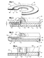
- the numeral 10 generally designates a faceplate for a two-piece ostomy appliance.
- the faceplate as shown is generally circular in outline, but other shapes, such as oval or generally rectangular with rounded corners, may be provided.
- the faceplate includes a wafer 11 and a coupling ring 12.
- the wafer comprises a layer 13 of moisture-absorbing adhesive skin barrier material having a bodyside surface covered by a removable release sheet 14 and an opposite surface covered by a thin backing layer 15.
- skin barrier is widely used in the medical field, and is used herein, to refer to any of a variety of materials in which a soft, sticky, and pliant adhesive composition constitutes a continuous phase and particles of one or more liquid-absorbing and swellable hydrocolloids are dispersed throughout the adhesive and constitute a discontinuous phase.
- the adhesive phase contains at least one elastomer such as polyisobutylene, often in combination with one or more tackifiers, plasticizers, and antioxidants.
- An elastomer such as a styrene-isoprene-styrene block copolymer (e.g., "Cariflex” TR-1107, from Shell Chemical Co.) or a styrene-butadiene-styrene block copolymer (e.g., "Kraton” 1100 Series from Shell Chemical Co.) may be included, and other ABA block copolymers, such as ethylene-propylene block copolymers known as EPR rubbers have also been included in adhesive compositions for increasing the elastomeric properties of such barrier materials.
- a styrene-isoprene-styrene block copolymer e.g., "Cariflex" TR-1107, from Shell Chemical Co.
- a styrene-butadiene-styrene block copolymer e.g., "Kraton” 1100 Series from Shell Chemical Co.
- the discontinuous phase may be particles of any suitable hydrocolloid or mixtures of hydrocolloids such as sodium carboxymethylcellulose, calcium, carboxymethyl-cellulose, pectin, gelatin, and natural gums such as guar gum, gum arabic, locust bean gum, karaya, and the like.
- hydrocolloids are water-absorbing and water-swellable. They absorb moisture from the skin and contribute to the wet-tack characteristics of the skin barrier material, all as well known in the art.
- wafer 11 may be contoured, having a relatively thick central body portion 11a and a thinner peripheral flange portion 11b.
- the thickness of the body portion increases the moisture absorbing capacity of the water and promotes an effective seal directly around a patient's stoma, whereas the thinnness of the peripheral portion enhances flexibility and compliance with the skin and reduces the possiblity that channeling and leakage might occur. While such contouring is considered highly advantageous, it is nevertheless optional and, if desired, the barrier thickness of the peripheral portion 11b may be the same as, or even greater than, the thickness of body portion 11a surrounding stoma opening 16.
- the removable release sheet 14 along the bodyside surface of the wafer is formed of any suitable material that is tough, flexible, and substantially non-stretchable. Siliconized paper may be used effectively.
- a polymeric material such as polyethylene terephthalate, is particularly desirable because of its high tensile strength and transparency, but other thermoplastic materials having similar properties may be used.
- An anti-stick coating of silicone may be provided on the release sheet and, if desired, a tab portion of the release sheet may project beyond the skin barrier layer 13 to facilitate removal of the release sheet when the faceplate is to be adhered to the skin.
- the backing layer 15 is composed of a heat-sealable material that is flexible and preferably elastomeric.
- a film of polyurethane is believed particularly effective but other polymeric films having similar properties may be used.
- the backing layer may be formed of a heat-sealable non-woven fabric which is preferably porous but not necessarily so.
- One such material that is believed particularly effective for this purpose is a breathable (i.e., gas-transmissible) non-woven fabric composed of spunbonded or meltblown thermoplastic fibers.
- Wafer 11, including adhesive layer 13, backing layer 15, and release sheet 14 is provided with a central opening 16 to serve as a starter opening which may then be enlarged (by cutting with scissors) to match the shape and size of a patient's stoma.
- the central opening may be pre-sized to eliminate the need for cutting at the time of application.
- connecting portion 12a is not critical to the present invention and that a ring having a connecting portion of somewhat different construction and operation may be provided. What is significant is that the annular connecting portion 12a should project axially away from the wafer, extend about a stoma-receiving opening 16, and be adapted for mechanically coupling to a second ring provided by an ostomy pouch.
- Wafer 11 has its pouchside surface provided with a recess 17 which, as shown in Figure 2, is dimensioned to receive a portion of coupling ring 12, specifically, the flange portion 12b of that coupling ring.
- the depth "d" of the recess, which is lined by backing layer 15, corresponds to the thickness of the flange portion 12b so that the top surface of the flange portion is flush with at least one adjacent surface 15a of the wafer.
- recess 17 has a pair of concentric annular side surfaces 17a and 17b that are normal to the plane of the wafer and a base surface 17c parallel with and below that of wafer surfaces 15a and 15b adjoining recess 17.
- the flange 12b of the coupling ring is securely affixed to the base surface 17 by any suitable means, most desirably by a heat seal 18 welding the flange to the thermoplastic backing layer 15 within the recess.
- the flange is therefore effectively embedded within the wafer with the result that faceplate 10 is of distinctively low profile with its flange portion anchored and concealed within the recess of the wafer.
- faceplate 10 is of distinctively low profile with its flange portion anchored and concealed within the recess of the wafer.
- Such a construction also has important functional advantages since it protects the peripheral edge portion of flange 12b and enhances the security of attachment between the coupling ring and the wafer.
- the reduced thickness of the barrier material beneath the base of the recess is considered advantageous because the greater flexibility of the barrier layer in that area tends to offset at least partially the decrease in flexibility occasioned by the presence of flange portion 12b.
- Cover layer 19 may be formed of any of a variety of flexible and stretchable materials. Most advantageously, it is composed of a soft, flexible and stretchable fabric, particularly a non-woven fabric such as spunbonded, low-density polyethylene fabric available under the designation "Daltex" 6080-A1-UPE from Don & Low Ltd., Forfar, Scotland. Other materials having somewhat similar properties that might be used include flexible and resilient polymeric foam materials of either open or closed cell structure.
- a pressure sensitive adhesive coating upon the bodyside surface of cover layer 19 secures that layer to both the flange 12b and the surface 15a of the backing layer adjoining recess 17.
- the embodiment of Figure 3 is similar to the one already described except that the thickness of the wafer 11' within the outline of coupling ring 12 is of substantially the same thickness as the portion of the wafer beneath flange 12b.
- the recess 17' therefore extends radially inwardly all the way to stoma-receiving opening 16'.
- Such a construction may be considered desirable where greater flexibility of that portion of the wafer inboard of the coupling ring is an objective and where high absorbency of the barrier layer about the edges of the stoma-receiving opening 16' is regarded as of lesser importance.
- the male coupling rings 12 of the embodiments already described are designed to mate with female coupling rings mounted on collection pouches (not shown).
- the arrangement may be reversed with the female ring provided by the faceplate and the male ring mounted on a pouch.
- the embodiment of Figure 4 therefore depicts a faceplate 10'' in which a female coupling ring 20 of annular channel-shaped configuration is secured to wafer 11''.
- the wafer is recessed at 17'' below adjoining surface 15''.
- the wafer has only one side surface 17b'' normal to base surface 17c'', it is to be understood that the thickness of the barrier material outboard of the coupling ring might be increased to provide the recess with a second side surface corresponding to surface 17a of the Figure 2 embodiment.
- the coupling ring whether male or female, be partially embedded within a recess formed in the pouchside surface of water 11, 11', or 11'', that the recess include a base surface to which the coupling ring is secured, preferably by heat seal 18 or 18'', and that the recess be defined by at least one side surface that extends generally normal to the plane of the wafer.
Landscapes
- Health & Medical Sciences (AREA)
- Epidemiology (AREA)
- Nursing (AREA)
- Orthopedic Medicine & Surgery (AREA)
- Engineering & Computer Science (AREA)
- Biomedical Technology (AREA)
- Heart & Thoracic Surgery (AREA)
- Vascular Medicine (AREA)
- Life Sciences & Earth Sciences (AREA)
- Animal Behavior & Ethology (AREA)
- General Health & Medical Sciences (AREA)
- Public Health (AREA)
- Veterinary Medicine (AREA)
- Chemical & Material Sciences (AREA)
- Dispersion Chemistry (AREA)
- Orthopedics, Nursing, And Contraception (AREA)
Abstract
Description
Claims (17)
- A faceplate for a two-piece ostomy appliance, said faceplate comprising a coupling ring for mechanically and detachably coupling said faceplate to a collection pouch and an adhesive wafer supporting said coupling ring for adhesively joining said faceplate to the peristomal skin surfaces of a patient; said wafer being generally planar and including a layer of hydrocolloid-containing adhesive skin barrier material; wherein the improvement comprises said wafer having a recess facing in the direction of said coupling ring and having at least one side surface generally normal to the plane of said wafer; said wafer also having a base surface extending along a plane below that of a surface of said wafer adjoining said recess; said coupling ring including a portion thereof received in said recess and secured to the said base surface of said recess beneath the plane of said adjoining surface.
- The faceplate of Claim 1 in which said wafer includes a thermoplastic backing layer along the surface thereof facing said coupling ring.
- The faceplate of Claim 2 in which said backing layer extends into said recess and along the base surface thereof.
- The faceplate of Claim 3 in which said coupling ring is heat sealed to said backing layer along the base surface of said recess.
- The faceplate of Claim 1 in which said coupling ring is a male coupling ring.
- The faceplate of Claim 1 in which said coupling ring is a female coupling ring.
- The faceplate of Claim 1 in which said skin barrier layer extends beneath said base surface of said coupling ring and has a thickness substantially less than the thickness of said barrier layer beneath said adjoining surface.
- The faceplate of Claim 7 in which said wafer includes surface portions facing said coupling ring and disposed inboard and outboard of said coupling ring; said adjoining surface being disposed outboard of said coupling ring.
- The faceplate of Claim 7 in which said wafer includes surface portions facing in the direction of said coupling ring and disposed inboard and outboard of said coupling ring; said adjoining surface being disposed inboard of said coupling ring.
- The faceplate of Claim 7 in which said wafer includes surface portions facing said coupling ring and disposed inboard and outboard of said coupling ring; said inboard surface being located both inboard and outboard of said coupling ring.
- The faceplate of Claims 8, 9 or 10 in which said wafer includes a backing layer covering said skin barrier layer and extending over said base surface in said recess; said backing layer being secured to said skin barrier layer by the adhesiveness of said skin barrier layer; said coupling ring being affixed to said backing layer within said recess.
- The fceplate of Claim 11 in which said backing layer and said coupling ring are each formed of thermoplastic heat-sealable material; said coupling ring being heat-sealed to said backing layer within said recess.
- A faceplate for a two-piece ostomy appliance, said faceplate comprising a coupling ring for mechanically and detachably coupling said faceplate to a collection pouch and an adhesive wafer supporting said coupling ring for adhesively joining said faceplate to the peristomal skin surfaces of a patient; said wafer being generally planar and including a layer of hydrocolloid-containing adhesive skin barrier material; said coupling ring including an annular connecting portion extending axially away from said wafer and a radially outwardly extending flange portion extending along the plane of said wafer; wherein the improvement comprises said wafer having a recess facing in the direction of said coupling ring and receiving the flange portion thereof; said wafer having a surface adjoining said recess that is flush with a surface of said flange facing away from said recess; and means securing said flange to said wafer within said recess.
- The faceplate of Claim 13 in which said wafer includes a backing layer covering said skin barrier layer and extending into said recess; said backing layer being secured to said skin barrier layer by the adhesiveness of said skin barrier layer; said flange portion of said coupling ring being affixed to said backing layer within said recess.
- The faceplate of Claim 14 in which said backing layer and said coupling ring are each formed of thermoplastic heat-sealable material; said flange portion of said coupling ring being heat-sealed to said backing layer within said recess.
- The faceplate of claims 13, 14 or 15 in which an annular covering layer extends about said coupling ring and covers both said flange portion and the adjacent surface of said wafer extending thereabout.
- The faceplate of Claim 16 in which said covering layer is formed of soft fabric and is adhesively secured to both said flange portion and said adjoining surface.
Applications Claiming Priority (2)
| Application Number | Priority Date | Filing Date | Title |
|---|---|---|---|
| US249561 | 1994-05-26 | ||
| US09/249,561 US6293930B1 (en) | 1998-06-11 | 1999-02-12 | Low-profile ostomy faceplate with recessed coupling ring |
Publications (3)
| Publication Number | Publication Date |
|---|---|
| EP1031334A2 true EP1031334A2 (en) | 2000-08-30 |
| EP1031334A3 EP1031334A3 (en) | 2001-01-10 |
| EP1031334B1 EP1031334B1 (en) | 2002-10-16 |
Family
ID=22944026
Family Applications (1)
| Application Number | Title | Priority Date | Filing Date |
|---|---|---|---|
| EP00300143A Expired - Lifetime EP1031334B1 (en) | 1999-02-12 | 2000-01-11 | Low-profile ostomy faceplate with recessed coupling ring |
Country Status (4)
| Country | Link |
|---|---|
| US (1) | US6293930B1 (en) |
| EP (1) | EP1031334B1 (en) |
| DE (1) | DE60000587T2 (en) |
| DK (1) | DK1031334T3 (en) |
Cited By (1)
| Publication number | Priority date | Publication date | Assignee | Title |
|---|---|---|---|---|
| US6293930B1 (en) * | 1998-06-11 | 2001-09-25 | Hollister Incorporated | Low-profile ostomy faceplate with recessed coupling ring |
Families Citing this family (29)
| Publication number | Priority date | Publication date | Assignee | Title |
|---|---|---|---|---|
| CA2518892A1 (en) | 2003-03-12 | 2004-09-23 | Avery Dennison Corporation | Reusable closures for packages and methods of making and using the same |
| US7811274B2 (en) | 2003-05-07 | 2010-10-12 | Portaero, Inc. | Method for treating chronic obstructive pulmonary disease |
| US7426929B2 (en) | 2003-05-20 | 2008-09-23 | Portaero, Inc. | Intra/extra-thoracic collateral ventilation bypass system and method |
| US7533667B2 (en) | 2003-05-29 | 2009-05-19 | Portaero, Inc. | Methods and devices to assist pulmonary decompression |
| US7252086B2 (en) | 2003-06-03 | 2007-08-07 | Cordis Corporation | Lung reduction system |
| US7377278B2 (en) | 2003-06-05 | 2008-05-27 | Portaero, Inc. | Intra-thoracic collateral ventilation bypass system and method |
| US7682332B2 (en) | 2003-07-15 | 2010-03-23 | Portaero, Inc. | Methods to accelerate wound healing in thoracic anastomosis applications |
| US7398782B2 (en) | 2004-11-19 | 2008-07-15 | Portaero, Inc. | Method for pulmonary drug delivery |
| US8220460B2 (en) | 2004-11-19 | 2012-07-17 | Portaero, Inc. | Evacuation device and method for creating a localized pleurodesis |
| US7824366B2 (en) | 2004-12-10 | 2010-11-02 | Portaero, Inc. | Collateral ventilation device with chest tube/evacuation features and method |
| US8104474B2 (en) | 2005-08-23 | 2012-01-31 | Portaero, Inc. | Collateral ventilation bypass system with retention features |
| US7406963B2 (en) | 2006-01-17 | 2008-08-05 | Portaero, Inc. | Variable resistance pulmonary ventilation bypass valve and method |
| US8163034B2 (en) | 2007-05-11 | 2012-04-24 | Portaero, Inc. | Methods and devices to create a chemically and/or mechanically localized pleurodesis |
| US7931641B2 (en) | 2007-05-11 | 2011-04-26 | Portaero, Inc. | Visceral pleura ring connector |
| US8062315B2 (en) | 2007-05-17 | 2011-11-22 | Portaero, Inc. | Variable parietal/visceral pleural coupling |
| US8475389B2 (en) | 2008-02-19 | 2013-07-02 | Portaero, Inc. | Methods and devices for assessment of pneumostoma function |
| EP2242527A4 (en) | 2008-02-19 | 2011-07-13 | Portaero Inc | DEVICES AND METHODS FOR ADMINISTERING A THERAPEUTIC AGENT THROUGH PNEUMOSTOMY |
| US8336540B2 (en) | 2008-02-19 | 2012-12-25 | Portaero, Inc. | Pneumostoma management device and method for treatment of chronic obstructive pulmonary disease |
| ATE545394T1 (en) | 2008-04-17 | 2012-03-15 | Coloplast As | DEVICE FOR COLLECTING BODY FLUID |
| US8328779B2 (en) * | 2008-05-30 | 2012-12-11 | Marlen Manufacturing & Development, Inc. | Locating flange for a two-piece ostomy adhesive mount |
| US8347881B2 (en) | 2009-01-08 | 2013-01-08 | Portaero, Inc. | Pneumostoma management device with integrated patency sensor and method |
| US8518053B2 (en) | 2009-02-11 | 2013-08-27 | Portaero, Inc. | Surgical instruments for creating a pneumostoma and treating chronic obstructive pulmonary disease |
| US9901487B2 (en) * | 2010-03-10 | 2018-02-27 | C. Howard Steinberg | Anus crevice insert |
| US8449513B2 (en) * | 2010-12-27 | 2013-05-28 | Benson Turtleneck Barrier, Llc | Ostomy barrier seal |
| GB201317667D0 (en) * | 2013-10-07 | 2013-11-20 | Welland Medical Ltd | Support film |
| AU2016211382B2 (en) * | 2015-01-28 | 2019-10-10 | Hollister Incorporated | Adhesive for moist tissue and peristomal device made using the same |
| US20180098876A1 (en) * | 2015-06-05 | 2018-04-12 | Better Ostomy, Llc | Ostomy appliance with fastening pads and related methods |
| US20170007439A1 (en) * | 2015-07-10 | 2017-01-12 | Thomas J. Boksan | Ostomy Appliance Collar |
| EP4271332A4 (en) * | 2020-12-31 | 2024-11-27 | ConvaTec Technologies Inc. | COUPLING SYSTEM FOR OSTOMY DEVICES |
Family Cites Families (14)
| Publication number | Priority date | Publication date | Assignee | Title |
|---|---|---|---|---|
| US4775374A (en) | 1981-11-27 | 1988-10-04 | E. R. Squibb & Sons, Inc. | Skin barrier for use by ostomates |
| US4610676A (en) * | 1984-05-17 | 1986-09-09 | Hollister Incorporated | Ostomy appliance coupling ring construction |
| US5026360A (en) * | 1989-06-27 | 1991-06-25 | E. R. Squibb & Sons | Clamping systems for two piece ostomy device |
| US5088992A (en) * | 1990-05-30 | 1992-02-18 | Edwards John V | Ostomy device with improved coupling system |
| US5185008A (en) | 1991-06-21 | 1993-02-09 | Hollister Incorporated | Two-piece ostomy appliance and coupling therefor with rocking wedge lock |
| ZA94720B (en) | 1993-02-08 | 1994-08-02 | Squibb & Sons Inc | Flushable ostomy pouch |
| DK75993D0 (en) * | 1993-06-25 | 1993-06-25 | Ole Jensen | A OSTOMY APPLIANCE COMPRISING A FLEXIBLE POUCH AND A FACEPLATE, A FLEXIBLE POUCH OF AN OSTOMY APPLIANCE, AND A FACEPLATE OF AN OSTOMY APPLIANCE |
| GB2299510B (en) | 1995-04-06 | 1997-03-12 | Squibb & Sons Inc | Ostomy coupling |
| US5609585A (en) * | 1995-08-01 | 1997-03-11 | Hollister Incorporated | Wafer having adhesive skin barrier layer |
| GB2290974B (en) | 1995-08-01 | 1996-06-19 | Squibb & Sons Inc | Body-side ostomy member |
| US5607413A (en) * | 1996-03-12 | 1997-03-04 | Dansac A/S | Convex ostomy faceplate with floating flange and finger recess |
| US5730736A (en) * | 1996-04-30 | 1998-03-24 | Dansac A/S | Ostomy appliance and contoured adhesive wafer therefor |
| US5947941A (en) * | 1998-03-05 | 1999-09-07 | Hollister Incorporated | Two-piece ostomy appliance |
| US6293930B1 (en) * | 1998-06-11 | 2001-09-25 | Hollister Incorporated | Low-profile ostomy faceplate with recessed coupling ring |
-
1999
- 1999-02-12 US US09/249,561 patent/US6293930B1/en not_active Expired - Fee Related
-
2000
- 2000-01-11 DK DK00300143T patent/DK1031334T3/en active
- 2000-01-11 DE DE60000587T patent/DE60000587T2/en not_active Expired - Fee Related
- 2000-01-11 EP EP00300143A patent/EP1031334B1/en not_active Expired - Lifetime
Cited By (1)
| Publication number | Priority date | Publication date | Assignee | Title |
|---|---|---|---|---|
| US6293930B1 (en) * | 1998-06-11 | 2001-09-25 | Hollister Incorporated | Low-profile ostomy faceplate with recessed coupling ring |
Also Published As
| Publication number | Publication date |
|---|---|
| DK1031334T3 (en) | 2003-02-17 |
| DE60000587T2 (en) | 2003-02-20 |
| EP1031334B1 (en) | 2002-10-16 |
| DE60000587D1 (en) | 2002-11-21 |
| EP1031334A3 (en) | 2001-01-10 |
| US6293930B1 (en) | 2001-09-25 |
Similar Documents
| Publication | Publication Date | Title |
|---|---|---|
| EP1031334B1 (en) | Low-profile ostomy faceplate with recessed coupling ring | |
| US6197010B1 (en) | Ostomy appliance faceplate with concealed coupling ring flange | |
| EP4403147B1 (en) | System including a skin-engageable element of an ostomy appliance | |
| EP0790048B2 (en) | One-piece ostomy appliance with pouch and faceplate integrating convex pressure ring | |
| US5811116A (en) | Adhesive wafer with embossed skin-contacting surface | |
| EP1101463B1 (en) | Ostomy appliance with inverted triangular faceplate and non-protruding pull tabs | |
| US8211073B2 (en) | Ostomy faceplate having moldable adhesive wafer with diminishing surface undulations | |
| US5607413A (en) | Convex ostomy faceplate with floating flange and finger recess | |
| US6106507A (en) | Ostomy appliance faceplate with barrier layer, extended covering layer, and unitary protective release sheet and method of making | |
| JPH0392153A (en) | Closure-attaching means for ostomy appliance | |
| JP2005500093A (en) | Ostomy appliance | |
| US20100114045A1 (en) | Ostomy pouch appliane | |
| AU2794300A (en) | An ostomy appliance | |
| RU2648835C2 (en) | Securement of collecting bags for human body wastes to skin | |
| JPH0728886B2 (en) | 2-piece ostomy appliance | |
| GB2418861A (en) | Adhesive flange for an ostomy bag | |
| CA3108574A1 (en) | Convex ostomy barrier and method of forming convex ostomy barriers of various softness | |
| GB2437059A (en) | Insert for the aperture of an adhesive flange for an ostomy device |
Legal Events
| Date | Code | Title | Description |
|---|---|---|---|
| PUAI | Public reference made under article 153(3) epc to a published international application that has entered the european phase |
Free format text: ORIGINAL CODE: 0009012 |
|
| AK | Designated contracting states |
Kind code of ref document: A2 Designated state(s): DE DK FR GB IT |
|
| AX | Request for extension of the european patent |
Free format text: AL;LT;LV;MK;RO;SI |
|
| PUAL | Search report despatched |
Free format text: ORIGINAL CODE: 0009013 |
|
| AK | Designated contracting states |
Kind code of ref document: A3 Designated state(s): DE DK FR GB IT |
|
| AX | Request for extension of the european patent |
Free format text: AL;LT;LV;MK;RO;SI |
|
| RIC1 | Information provided on ipc code assigned before grant |
Free format text: 7A 61F 5/44 A, 7A 61F 5/443 B, 7A 61F 5/448 B |
|
| 17P | Request for examination filed |
Effective date: 20010215 |
|
| 17Q | First examination report despatched |
Effective date: 20010731 |
|
| AKX | Designation fees paid |
Free format text: DE DK FR GB IT |
|
| GRAG | Despatch of communication of intention to grant |
Free format text: ORIGINAL CODE: EPIDOS AGRA |
|
| GRAG | Despatch of communication of intention to grant |
Free format text: ORIGINAL CODE: EPIDOS AGRA |
|
| GRAH | Despatch of communication of intention to grant a patent |
Free format text: ORIGINAL CODE: EPIDOS IGRA |
|
| GRAH | Despatch of communication of intention to grant a patent |
Free format text: ORIGINAL CODE: EPIDOS IGRA |
|
| GRAA | (expected) grant |
Free format text: ORIGINAL CODE: 0009210 |
|
| AK | Designated contracting states |
Kind code of ref document: B1 Designated state(s): DE DK FR GB IT |
|
| REG | Reference to a national code |
Ref country code: GB Ref legal event code: FG4D |
|
| REF | Corresponds to: |
Ref document number: 60000587 Country of ref document: DE Date of ref document: 20021121 |
|
| REG | Reference to a national code |
Ref country code: DK Ref legal event code: T3 |
|
| ET | Fr: translation filed | ||
| PLBE | No opposition filed within time limit |
Free format text: ORIGINAL CODE: 0009261 |
|
| STAA | Information on the status of an ep patent application or granted ep patent |
Free format text: STATUS: NO OPPOSITION FILED WITHIN TIME LIMIT |
|
| 26N | No opposition filed |
Effective date: 20030717 |
|
| PGFP | Annual fee paid to national office [announced via postgrant information from national office to epo] |
Ref country code: GB Payment date: 20050105 Year of fee payment: 6 |
|
| PGFP | Annual fee paid to national office [announced via postgrant information from national office to epo] |
Ref country code: DE Payment date: 20050106 Year of fee payment: 6 |
|
| PGFP | Annual fee paid to national office [announced via postgrant information from national office to epo] |
Ref country code: FR Payment date: 20050110 Year of fee payment: 6 |
|
| PGFP | Annual fee paid to national office [announced via postgrant information from national office to epo] |
Ref country code: DK Payment date: 20050114 Year of fee payment: 6 |
|
| PG25 | Lapsed in a contracting state [announced via postgrant information from national office to epo] |
Ref country code: GB Free format text: LAPSE BECAUSE OF NON-PAYMENT OF DUE FEES Effective date: 20060111 |
|
| PG25 | Lapsed in a contracting state [announced via postgrant information from national office to epo] |
Ref country code: FR Free format text: LAPSE BECAUSE OF NON-PAYMENT OF DUE FEES Effective date: 20060131 Ref country code: DK Free format text: LAPSE BECAUSE OF NON-PAYMENT OF DUE FEES Effective date: 20060131 |
|
| PGFP | Annual fee paid to national office [announced via postgrant information from national office to epo] |
Ref country code: IT Payment date: 20060131 Year of fee payment: 7 |
|
| PG25 | Lapsed in a contracting state [announced via postgrant information from national office to epo] |
Ref country code: DE Free format text: LAPSE BECAUSE OF NON-PAYMENT OF DUE FEES Effective date: 20060801 |
|
| REG | Reference to a national code |
Ref country code: DK Ref legal event code: EBP |
|
| GBPC | Gb: european patent ceased through non-payment of renewal fee |
Effective date: 20060111 |
|
| REG | Reference to a national code |
Ref country code: FR Ref legal event code: ST Effective date: 20060929 |
|
| PG25 | Lapsed in a contracting state [announced via postgrant information from national office to epo] |
Ref country code: IT Free format text: LAPSE BECAUSE OF NON-PAYMENT OF DUE FEES Effective date: 20070111 |