EP1030317A2 - Quenched thin ribbon of rare earth/iron/boron-based magnet alloy - Google Patents
Quenched thin ribbon of rare earth/iron/boron-based magnet alloy Download PDFInfo
- Publication number
- EP1030317A2 EP1030317A2 EP00400414A EP00400414A EP1030317A2 EP 1030317 A2 EP1030317 A2 EP 1030317A2 EP 00400414 A EP00400414 A EP 00400414A EP 00400414 A EP00400414 A EP 00400414A EP 1030317 A2 EP1030317 A2 EP 1030317A2
- Authority
- EP
- European Patent Office
- Prior art keywords
- phase
- rare earth
- iron
- alloy
- magnet alloy
- Prior art date
- Legal status (The legal status is an assumption and is not a legal conclusion. Google has not performed a legal analysis and makes no representation as to the accuracy of the status listed.)
- Granted
Links
Images



Classifications
-
- B—PERFORMING OPERATIONS; TRANSPORTING
- B82—NANOTECHNOLOGY
- B82Y—SPECIFIC USES OR APPLICATIONS OF NANOSTRUCTURES; MEASUREMENT OR ANALYSIS OF NANOSTRUCTURES; MANUFACTURE OR TREATMENT OF NANOSTRUCTURES
- B82Y25/00—Nanomagnetism, e.g. magnetoimpedance, anisotropic magnetoresistance, giant magnetoresistance or tunneling magnetoresistance
-
- A—HUMAN NECESSITIES
- A63—SPORTS; GAMES; AMUSEMENTS
- A63B—APPARATUS FOR PHYSICAL TRAINING, GYMNASTICS, SWIMMING, CLIMBING, OR FENCING; BALL GAMES; TRAINING EQUIPMENT
- A63B53/00—Golf clubs
- A63B53/007—Putters
-
- A—HUMAN NECESSITIES
- A63—SPORTS; GAMES; AMUSEMENTS
- A63B—APPARATUS FOR PHYSICAL TRAINING, GYMNASTICS, SWIMMING, CLIMBING, OR FENCING; BALL GAMES; TRAINING EQUIPMENT
- A63B53/00—Golf clubs
- A63B53/14—Handles
-
- A—HUMAN NECESSITIES
- A63—SPORTS; GAMES; AMUSEMENTS
- A63B—APPARATUS FOR PHYSICAL TRAINING, GYMNASTICS, SWIMMING, CLIMBING, OR FENCING; BALL GAMES; TRAINING EQUIPMENT
- A63B60/00—Details or accessories of golf clubs, bats, rackets or the like
- A63B60/06—Handles
- A63B60/22—Adjustable handles
-
- A—HUMAN NECESSITIES
- A63—SPORTS; GAMES; AMUSEMENTS
- A63B—APPARATUS FOR PHYSICAL TRAINING, GYMNASTICS, SWIMMING, CLIMBING, OR FENCING; BALL GAMES; TRAINING EQUIPMENT
- A63B60/00—Details or accessories of golf clubs, bats, rackets or the like
- A63B60/06—Handles
- A63B60/32—Handles with means for changing the angular position of the handle about its longitudinal axis
-
- B—PERFORMING OPERATIONS; TRANSPORTING
- B22—CASTING; POWDER METALLURGY
- B22F—WORKING METALLIC POWDER; MANUFACTURE OF ARTICLES FROM METALLIC POWDER; MAKING METALLIC POWDER; APPARATUS OR DEVICES SPECIALLY ADAPTED FOR METALLIC POWDER
- B22F9/00—Making metallic powder or suspensions thereof
- B22F9/02—Making metallic powder or suspensions thereof using physical processes
- B22F9/023—Hydrogen absorption
-
- H—ELECTRICITY
- H01—ELECTRIC ELEMENTS
- H01F—MAGNETS; INDUCTANCES; TRANSFORMERS; SELECTION OF MATERIALS FOR THEIR MAGNETIC PROPERTIES
- H01F1/00—Magnets or magnetic bodies characterised by the magnetic materials therefor; Selection of materials for their magnetic properties
- H01F1/01—Magnets or magnetic bodies characterised by the magnetic materials therefor; Selection of materials for their magnetic properties of inorganic materials
- H01F1/03—Magnets or magnetic bodies characterised by the magnetic materials therefor; Selection of materials for their magnetic properties of inorganic materials characterised by their coercivity
- H01F1/032—Magnets or magnetic bodies characterised by the magnetic materials therefor; Selection of materials for their magnetic properties of inorganic materials characterised by their coercivity of hard-magnetic materials
- H01F1/04—Magnets or magnetic bodies characterised by the magnetic materials therefor; Selection of materials for their magnetic properties of inorganic materials characterised by their coercivity of hard-magnetic materials metals or alloys
- H01F1/047—Alloys characterised by their composition
- H01F1/053—Alloys characterised by their composition containing rare earth metals
- H01F1/055—Alloys characterised by their composition containing rare earth metals and magnetic transition metals, e.g. SmCo5
- H01F1/057—Alloys characterised by their composition containing rare earth metals and magnetic transition metals, e.g. SmCo5 and IIIa elements, e.g. Nd2Fe14B
- H01F1/0571—Alloys characterised by their composition containing rare earth metals and magnetic transition metals, e.g. SmCo5 and IIIa elements, e.g. Nd2Fe14B in the form of particles, e.g. rapid quenched powders or ribbon flakes
-
- H—ELECTRICITY
- H01—ELECTRIC ELEMENTS
- H01F—MAGNETS; INDUCTANCES; TRANSFORMERS; SELECTION OF MATERIALS FOR THEIR MAGNETIC PROPERTIES
- H01F1/00—Magnets or magnetic bodies characterised by the magnetic materials therefor; Selection of materials for their magnetic properties
- H01F1/01—Magnets or magnetic bodies characterised by the magnetic materials therefor; Selection of materials for their magnetic properties of inorganic materials
- H01F1/03—Magnets or magnetic bodies characterised by the magnetic materials therefor; Selection of materials for their magnetic properties of inorganic materials characterised by their coercivity
- H01F1/032—Magnets or magnetic bodies characterised by the magnetic materials therefor; Selection of materials for their magnetic properties of inorganic materials characterised by their coercivity of hard-magnetic materials
- H01F1/04—Magnets or magnetic bodies characterised by the magnetic materials therefor; Selection of materials for their magnetic properties of inorganic materials characterised by their coercivity of hard-magnetic materials metals or alloys
- H01F1/047—Alloys characterised by their composition
- H01F1/053—Alloys characterised by their composition containing rare earth metals
- H01F1/055—Alloys characterised by their composition containing rare earth metals and magnetic transition metals, e.g. SmCo5
- H01F1/057—Alloys characterised by their composition containing rare earth metals and magnetic transition metals, e.g. SmCo5 and IIIa elements, e.g. Nd2Fe14B
- H01F1/0571—Alloys characterised by their composition containing rare earth metals and magnetic transition metals, e.g. SmCo5 and IIIa elements, e.g. Nd2Fe14B in the form of particles, e.g. rapid quenched powders or ribbon flakes
- H01F1/0573—Alloys characterised by their composition containing rare earth metals and magnetic transition metals, e.g. SmCo5 and IIIa elements, e.g. Nd2Fe14B in the form of particles, e.g. rapid quenched powders or ribbon flakes obtained by reduction or by hydrogen decrepitation or embrittlement
-
- H—ELECTRICITY
- H01—ELECTRIC ELEMENTS
- H01F—MAGNETS; INDUCTANCES; TRANSFORMERS; SELECTION OF MATERIALS FOR THEIR MAGNETIC PROPERTIES
- H01F1/00—Magnets or magnetic bodies characterised by the magnetic materials therefor; Selection of materials for their magnetic properties
- H01F1/01—Magnets or magnetic bodies characterised by the magnetic materials therefor; Selection of materials for their magnetic properties of inorganic materials
- H01F1/03—Magnets or magnetic bodies characterised by the magnetic materials therefor; Selection of materials for their magnetic properties of inorganic materials characterised by their coercivity
- H01F1/032—Magnets or magnetic bodies characterised by the magnetic materials therefor; Selection of materials for their magnetic properties of inorganic materials characterised by their coercivity of hard-magnetic materials
- H01F1/04—Magnets or magnetic bodies characterised by the magnetic materials therefor; Selection of materials for their magnetic properties of inorganic materials characterised by their coercivity of hard-magnetic materials metals or alloys
- H01F1/047—Alloys characterised by their composition
- H01F1/053—Alloys characterised by their composition containing rare earth metals
- H01F1/055—Alloys characterised by their composition containing rare earth metals and magnetic transition metals, e.g. SmCo5
- H01F1/057—Alloys characterised by their composition containing rare earth metals and magnetic transition metals, e.g. SmCo5 and IIIa elements, e.g. Nd2Fe14B
- H01F1/0571—Alloys characterised by their composition containing rare earth metals and magnetic transition metals, e.g. SmCo5 and IIIa elements, e.g. Nd2Fe14B in the form of particles, e.g. rapid quenched powders or ribbon flakes
- H01F1/0575—Alloys characterised by their composition containing rare earth metals and magnetic transition metals, e.g. SmCo5 and IIIa elements, e.g. Nd2Fe14B in the form of particles, e.g. rapid quenched powders or ribbon flakes pressed, sintered or bonded together
- H01F1/0577—Alloys characterised by their composition containing rare earth metals and magnetic transition metals, e.g. SmCo5 and IIIa elements, e.g. Nd2Fe14B in the form of particles, e.g. rapid quenched powders or ribbon flakes pressed, sintered or bonded together sintered
-
- H—ELECTRICITY
- H01—ELECTRIC ELEMENTS
- H01F—MAGNETS; INDUCTANCES; TRANSFORMERS; SELECTION OF MATERIALS FOR THEIR MAGNETIC PROPERTIES
- H01F1/00—Magnets or magnetic bodies characterised by the magnetic materials therefor; Selection of materials for their magnetic properties
- H01F1/01—Magnets or magnetic bodies characterised by the magnetic materials therefor; Selection of materials for their magnetic properties of inorganic materials
- H01F1/03—Magnets or magnetic bodies characterised by the magnetic materials therefor; Selection of materials for their magnetic properties of inorganic materials characterised by their coercivity
- H01F1/032—Magnets or magnetic bodies characterised by the magnetic materials therefor; Selection of materials for their magnetic properties of inorganic materials characterised by their coercivity of hard-magnetic materials
- H01F1/04—Magnets or magnetic bodies characterised by the magnetic materials therefor; Selection of materials for their magnetic properties of inorganic materials characterised by their coercivity of hard-magnetic materials metals or alloys
- H01F1/047—Alloys characterised by their composition
- H01F1/053—Alloys characterised by their composition containing rare earth metals
- H01F1/055—Alloys characterised by their composition containing rare earth metals and magnetic transition metals, e.g. SmCo5
- H01F1/057—Alloys characterised by their composition containing rare earth metals and magnetic transition metals, e.g. SmCo5 and IIIa elements, e.g. Nd2Fe14B
- H01F1/0579—Alloys characterised by their composition containing rare earth metals and magnetic transition metals, e.g. SmCo5 and IIIa elements, e.g. Nd2Fe14B with exchange spin coupling between hard and soft nanophases, e.g. nanocomposite spring magnets
Definitions
- the present invention relates to a thin ribbon of a rare earth/ iron/boron-based magnet alloy prepared by the strip casting method and useful as a base material of a rare earth-based permanent magnet having greatly improved magnetic properties.
- Permanent magnets belong to a class of very important key materials in a great variety of instruments built under the most advanced technology in the field of electric and electronic industries covering from household electric appliances in general to peripheral terminals of computers and medical instruments. Along with the recent progress in the fields of computers and communication instruments, the electric and electronic instruments are desired to be more and more compact in size and lighter and lighter in weight and to exhibit higher and higher performance. It is apparent that these requirements cannot be satisfied without great upgrading of the permanent magnets built in the instruments as a key component.
- rare earth-based permanent magnets are widely used in the above mentioned fields as a class of high-performance permanent magnets, of which the rare earth/iron/boron-based magnets are the most promising in respect of their outstandingly excellent magnetic properties and economical advantages due to the relatively low material costs.
- the rare earth/iron/boron-based or, in particular, neodymium/iron/boron-based permanent magnet alloy is prepared usually by the mold casting method or by the strip casting method.
- the magnet alloy prepared by these methods is processed into a permanent magnet by the well known powder metallurgical process involving the step of magnetic orientation of the alloy particles under compression molding in a magnetic field.
- the constituent elements each in the metallic or elementary form are melted together in a crucible to give an alloy melt which is cast into a casting mold followed by solidification therein to give an ingot of the alloy which is processed into magnets by the powder metallurgical method.
- This method is widely practiced in respect of the advantage that the chemical composition of the magnet alloy can easily be controlled.
- a problem in the mold casting method described above is that, since the velocity of heat transfer is relatively low between the mold walls and the alloy melt and within the alloy melt per se, a long time is taken for solidification of the whole volume of the melt to give a solid of the magnet alloy so that the ⁇ -iron is crystallized as the primary crystals during the process of solidification of the molten alloy to form grains of the r - iron phase having a diameter of 10 ⁇ m or larger left in the core portion of the ingot block.
- the phase rich in the content of the rare earth element referred to as a R-rich phase hereinafter, and the R x T 4 B 4 phase, in which R is a rare earth element or a combination of rare earth elements, T is a transition metal element or typically iron and the subscript x is a positive number larger than 1 varying with the content of the rare earth element, surrounding the R 2 T 14 B phase as the principal phase in the permanent magnet are in the form of coarse grains of a large diameter.
- the metallographic structure of the alloy ingot cannot be uniform enough between the surface layer of the ingot solidified in contact with or in the vicinity of the mold wall and the core portion of the ingot remote from the surface layer due to non-uniformity in the cooling rate resulting in variations in the grain diameter of the R 2 T I4 B phase and the R-rich phase. Consequently, difficulties are encountered in the process of pulverization of the alloy ingot into a fine powder having a particle diameter of a few ⁇ m and the particle size distribution of the alloy powder cannot be uniform enough adversely affecting the magnetic properties of the permanent magnets finally obtained by the powder metallurgical method due to poor magnetic orientation of the alloy particles and poor sintering behavior of the powder compact.
- a melt of the magnet alloy is continuously ejected at the surface of a rotating quenching roller of the single-roller type or twin-roller type to prepare a thin ribbon of the solidified alloy having a thickness of 0.01 to 5 mm.
- This method is advantageous for obtaining a high-performance R/T/B-based permanent magnet because the metallographic phase structure of the magnet alloy in the form of a thin ribbon can be controlled by adequately selecting the quenching conditions of the alloy melt. For example, precipitation of the ⁇ -iron phase can be decreased or the R-rich phase and the R x T 4 B 4 phase can be dispersed with increased fineness and uniformity.
- the present invention accordingly has an object, by directing the inventors' attention to the above mentioned four-phase region, to provide a quenched thin ribbon of the R/T/B-based magnet alloy, from which a rare earth-based permanent magnet having greatly improved magnetic properties can be prepared by the powder metallurgical process.
- a thin ribbon of a rare earth-based magnet alloy which is a product by the strip casting method, having a metallographic phase structure of which the volume fraction of the four-phase region consisting of (a) an ⁇ -iron phase in a grain diameter of 0.1 to 20 ⁇ m, (b) a R-rich phase, in which R is a rare earth element selected from praseodymium, neodymium, terbium and dysprosium, in a grain diameter of 0.1 to 20 ⁇ m, (c) a R x T 4 B 4 phase, in which R has the same meaning as defined above, T is iron or a combination of iron and a transition metal element other than iron and the rare earth elements and x is a positive number larger than 1 varying with the content of the rare earth element, in a grain diameter of 0.1 to 10 ⁇ m and (d) a R 2 T 14 B phase, in which R and T each have the same meaning as defined above, in a
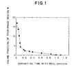
- Figure 1 is a graph showing the volume fraction of the four-phase region in the quenched thin ribbons as a function of the contacting time of the melt with the quenching roller.
- Figure 2 is a photographic reflected electron image of the four-phase region in a thin alloy ribbon.
- Figure 3 is a photographic secondary electron image of the four-phase region in a thin alloy ribbon.
- Figures 4 and 5 are each an Auger electron spectrum of the spots 1 and 2, respectively, indicated on the photograph of Figure 3.
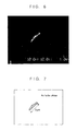
- Figures 6 and 7 are an Auger electron image photograph and a schematic sketch of the same view field, respectively, in a thin alloy ribbon showing the R x T 4 B 4 phase.
- Figures 8 and 9 are each a graph showing the residual magnetic flux density Br of the permanent magnets prepared in Example 1 and in Example 2, respectively, as a function of the volume fraction of the four-phase region in the thin alloy ribbon.
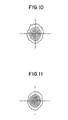
- Figures 10 and 11 are each a (006) pole figure of the sintered magnet body prepared from a thin alloy ribbon of which the volume fraction of the four-phase region is 0.5% and 3%, respectively.
- the above defined thin ribbon of a rare earth-based magnet alloy is a result of the extensive studies conducted by the inventors on the relationship between the metallographic phase structure of the thin alloy ribbon and the magnetic properties of the permanent magnet prepared from the thin alloy ribbon leading to an unexpected discovery that a greatly improved residual magnetic flux density of the permanent magnet can be obtained when the volume fraction of the four-phase region jointly consisting of the ⁇ -iron phase, R-rich phase, R x T 4 B 4 phase and R 2 T 14 B phase in the thin alloy ribbon is within a specific range and the grain diameter of each of these four phases is within a specific range.
- the thin ribbon of the rare earth-based magnet alloy defined above is a product prepared by the strip casting method from an alloy melt consisting mainly of a rare earth element, iron and boron. Namely, the alloy melt is ejected continuously at the surface of a single-roller type or twin roller-type quenching roller system where the alloy melt is quenched and solidified into the form of a thin ribbon having a thickness usually in the range from 10 to 500 ⁇ m and a width in the range from 5 to 500 mm depending on the dimensions of the quenching roller.
- the characterizing parameters of the inventive thin alloy ribbon relative to the volume fraction of the four-phase region and the grain diameter of each of these four phases can be controlled within the above specified ranges by adequately selecting the quenching conditions in the strip casting method.
- the quenching rate of the melt on the quenching roller is preferably in the range from 500 to 10000°C/second and the contacting time of the alloy melt with the surface of the quenching roller is at least 0.1 second or, preferably, in the range from 0.1 to 0.4 second.
- the value of ⁇ which is 0.1 or a number somewhat larger than 0.1 depending on the rare earth elements, as reported include the values of 0.10-0.11 for praseodymium, 0.10-0.11 for neodymium, 0.14-0.16 for terbium and 0.15-0.16 for dysprosium.
- the crystalline grains essentially have a grain diameter in the range from 0.1 to 20 ⁇ m or preferably from 0.1 to 10 ⁇ m, from 0.1 to 20 ⁇ m or preferably from 0.1 to 10 ⁇ m, from 0.1 to 10 ⁇ m or preferably from 0.1 to 5 ⁇ m and from 0.1 to 20 ⁇ m or preferably from 0.1 to 10 ⁇ m, respectively.
- the average grain diameter of the phases (a), (b) and (d) can be determined by examining the secondary electron image or the reflected electron image taken for a cross section of the thin alloy ribbon. This technique, however, is not applicable to the R x T 4 B 4 phase which is rich in the content of boron little susceptible to and hardly detectable by the reflected electron images. Instead, the average grain diameter of this phase can be determined by examining the Auger electron image taken for a broken-out section of the thin alloy ribbon.
- the thin alloy ribbon of the invention contains the above described four-phase region essentially in a volume fraction in the range from 1 to 10% or, preferably, from 2 to 5%.
- a volume fraction of the four-phase region is too large, a great decrease is resulted in the residual magnetic flux density and the coercive force of the permanent magnet prepared from the thin alloy ribbon.
- the volume fraction thereof is too small, substantially no improvement can be obtained in the residual magnetic flux density of the permanent magnet.
- the volume fraction of the four-phase region in the inventive thin alloy ribbon can be determined from the secondary electron image or reflected electron image taken for a cross section of the thin alloy ribbon.
- the thin ribbon of the magnet alloy prepared in the above described manner is processed into a sintered permanent magnet by pulverizing, optionally, after hydrogen decrepitation, compression-molding in a magnetic field, sintering in an inert atmosphere at 900 to 1150°C and finally aging at 400 to 600°C.
- a thin ribbon of a rare earth-based magnet alloy was prepared by the strip casting method from an alloy melt obtained by melting together neodymium metal, dysprosium metal, electrolytic iron, cobalt metal, ferroboron, aluminum metal and copper metal in such a proportion as to give an alloy composition of 30.0% by weight of neodymium, 1.0% by weight of dysprosium, 4.0% by weight of cobalt, 1.1% by weight of boron, 0.3% by weight of aluminum and 0.2% by weight of copper, the balance to 100% being iron.
- the volume fraction of the four-phase region in the thin alloy ribbons was varied in the range from 0 to 13.7% by controlling the contacting time of the alloy melt with the surface of the quenching roller in the range from 0.02 to 1.0 second.
- the cooling rate of the alloy melt was in the range from 5000 to 9000°C/second.
- the four phases (a), (b), (c) and (d) constituting the four-phase region each had an average grain diameter of 3 ⁇ m, 7 ⁇ m, 1 ⁇ m and 10 ⁇ m, respectively.
- Figure 1 is a graph showing the volume fraction of the four-phase region in the thin ribbons as a function of the contacting time. As is clear from this figure, the volume fraction of the four-phase region is decreased as a trend as the contacting time is increased. When the contacting time is 0.1 to 0.4 second, in particular, the volume fraction of the four-phase region is preferably in the desirable range from 2 to 5% by volume
- Figure 2 is a reflected electron image taken for a cross section of one of the above prepared thin alloy ribbons containing 5% by volume of the four-phase region.
- the black speckles correspond to the ⁇ -iron phase
- the gray areas correspond to the R 2 T 14 B phase
- the white areas correspond to the R-rich phase.
- the photograph shows fine and uniform dispersion of each of these three phases within the four-phase region.
- the R x T 4 B 4 phase is not susceptible to the determination of the average grain diameter due to the high content of boron from which the reflected electrons can hardly be detected.
- Figure 3 is a secondary electron image of the four-phase region of the same thin alloy ribbon as for Figure 2, of which an Auger electron spectrum was taken for the spot 1 or 2 indicated on the photograph of Figure 3 to give the results shown in Figures 4 and 5, respectively. Comparison of these spectra leads to a conclusion that the spot 1 corresponds to the R x T 4 B 4 phase which is richer in the content of boron than the peripheral phase at the spot 2 within the four-phase region.
- Figure 6 is a photographic Auger electron image of boron in the R x T 4 B 4 phase.
- Figure 7 is a schematic sketch of the same view field which indicates that the phase is dispersed in the four-phase region with a grain dimension of about 3 ⁇ m.
- each of the thin alloy ribbons was subjected first to a hydrogenation treatment and then to a dehydrogenation treatment followed by pulverization in a jet mill with nitrogen as the jet gas to give a fine alloy powder having an average particle diameter of about 3 ⁇ m.
- the alloy powder was compression-molded in a metal mold under a compressive pressure of 1 ton/cm 2 within a magnetic field of 12 kOe in a direction perpendicular to the direction of compression to give a powder compact which was subjected to a sintering heat treatment in an atmosphere of argon first by heating at 1050°C for 2 hours followed by cooling and then by heating at 500°C for 1 hour to effect aging giving a sintered permanent magnet.
- the procedure for the preparation of thin alloy ribbons was about the same as in Example 1 except that the alloy melt was prepared from the same base materials in such a proportion corresponding to 28.0% by weight of neodymium, 1.0% by weight of cobalt, 1.1 % by weight of boron and 0.3% by weight of aluminum, the balance to 100% being iron, and that the quenching conditions in the strip casting were controlled so as to give thin alloy ribbons of which the volume fraction of the four-phase region was varied in the range from 0 to 13.5%.
- the grain diameters of the four phases (a), (b), (c) and (d) were 3 ⁇ m, 5 ⁇ m, 1 ⁇ m and 10 ⁇ m, respectively.
- the fine powder of the thin alloy ribbon was admixed with a small amount of a sintering aid and subjected to a sintering heat treatment in the same manner as in Example 1 to give sintered permanent magnets.
Landscapes
- Chemical & Material Sciences (AREA)
- Engineering & Computer Science (AREA)
- Crystallography & Structural Chemistry (AREA)
- Inorganic Chemistry (AREA)
- Power Engineering (AREA)
- Physical Education & Sports Medicine (AREA)
- Health & Medical Sciences (AREA)
- General Health & Medical Sciences (AREA)
- Nanotechnology (AREA)
- Composite Materials (AREA)
- Hard Magnetic Materials (AREA)
- Manufacturing Cores, Coils, And Magnets (AREA)
- Continuous Casting (AREA)
- Powder Metallurgy (AREA)
Abstract
Description
Claims (6)
- A thin ribbon of a rare earth-based magnet alloy, which is a product by the strip casting method, having a metallographic phase structure of which the volume fraction of the four-phase region consisting of (a) an α-iron phase in a grain diameter of 0.1 to 20 µm, (b) a R-rich phase which is a phase richer in the content of the rare earth element than in R2T14B phase, R being a rare earth element selected from praseodymium, neodymium, terbium and dysprosium, in a grain diameter of 0.1 to 20 µm, (c) a RxT4B4 phase, in which R has the same meaning as defined above, T is iron or a combination of iron and a transition metal element other than iron and the rare earth elements and x is a positive number larger than 1 varying with the rare earth element, in a grain diameter of 0.1 to 10 µm and (d) a R2T14B phase, in which R and T each have the same meaning as defined above, in a grain diameter of 0.1 to 20 µm, each phase being uniformly dispersed in the four-phase region, is in the range from 1 to 20% by volume, with the proviso that the rest of the volume fraction consists of the R-rich phase, RxT4B4 phase and R2T14B phase or consists of the R-rich phase and R2T14B phase.
- The thin ribbon of a rare earth-based magnet alloy as claimed in claim 1 of which the volume fraction of the four-phase region is in the range from 2 to 5%.
- The thin ribbon of a rare earth-based magnet alloy as claimed in claim 1 in which the phases (a), (b), (c) and (d) in the four-phase region have grain diameters in the ranges from 0.1 to 10 µm, from 0.1 to 10 µm, from 0.1 to 5 µm and from 0.1 to 10 µm, respectively.
- The thin ribbon of a rare earth-based magnet alloy as claimed in claim 1 in which the transition metal element denoted by T other than iron and the rare earth elements is cobalt.
- A powder of a rare earth-based magnet alloy which is a product obtained by hydrogen decrepitation and pulverization of the thin ribbon of a rare earth-based magnet alloy defined in claim 1.
- A rare earth-based permanent magnet which is a sintered body of a powder of the thin ribbon of a rare earth-based magnet alloy as defined in claim 1.
Applications Claiming Priority (2)
| Application Number | Priority Date | Filing Date | Title |
|---|---|---|---|
| JP3539499 | 1999-02-15 | ||
| JP3539499 | 1999-02-15 |
Publications (3)
| Publication Number | Publication Date |
|---|---|
| EP1030317A2 true EP1030317A2 (en) | 2000-08-23 |
| EP1030317A3 EP1030317A3 (en) | 2001-01-03 |
| EP1030317B1 EP1030317B1 (en) | 2004-04-14 |
Family
ID=12440715
Family Applications (1)
| Application Number | Title | Priority Date | Filing Date |
|---|---|---|---|
| EP00400414A Expired - Lifetime EP1030317B1 (en) | 1999-02-15 | 2000-02-14 | Quenched thin ribbon of rare earth/iron/boron-based magnet alloy |
Country Status (6)
| Country | Link |
|---|---|
| US (2) | US6319335B1 (en) |
| EP (1) | EP1030317B1 (en) |
| KR (1) | KR100468603B1 (en) |
| CN (1) | CN1106453C (en) |
| DE (1) | DE60009772T2 (en) |
| TW (1) | TW487937B (en) |
Cited By (4)
| Publication number | Priority date | Publication date | Assignee | Title |
|---|---|---|---|---|
| EP1398800A4 (en) * | 2001-06-19 | 2004-11-03 | Mitsubishi Electric Corp | SUSTAINABLE MAGNETIC MATERIAL FROM THE RARE EARTH GROUP |
| EP1059645B1 (en) * | 1999-06-08 | 2006-06-14 | Shin-Etsu Chemical Co., Ltd. | Thin ribbon of rare earth-based permanent magnet alloy |
| US7705233B2 (en) * | 2002-08-13 | 2010-04-27 | Showa Denko K.K. | Filled skutterudite-based alloy, production method thereof and thermoelectric conversion device fabricated using the alloy |
| CN108380852A (en) * | 2018-02-12 | 2018-08-10 | 上海大学 | The method in magnetic field and cooling rate regulation and control Mg-Nd alloy object phases |
Families Citing this family (17)
| Publication number | Priority date | Publication date | Assignee | Title |
|---|---|---|---|---|
| US6319335B1 (en) * | 1999-02-15 | 2001-11-20 | Shin-Etsu Chemical Co., Ltd. | Quenched thin ribbon of rare earth/iron/boron-based magnet alloy |
| DE60140783D1 (en) * | 2000-09-08 | 2010-01-28 | Shinetsu Chemical Co | Rare earth alloy, rare earth sintered magnet and manufacturing process |
| US6676773B2 (en) * | 2000-11-08 | 2004-01-13 | Sumitomo Special Metals Co., Ltd. | Rare earth magnet and method for producing the magnet |
| CN100368584C (en) * | 2004-04-27 | 2008-02-13 | 有研稀土新材料股份有限公司 | Rare earth magnetostrictive material preparation method and the material |
| US7472041B2 (en) * | 2005-08-26 | 2008-12-30 | Step Communications Corporation | Method and apparatus for accommodating device and/or signal mismatch in a sensor array |
| JP4737431B2 (en) * | 2006-08-30 | 2011-08-03 | 信越化学工業株式会社 | Permanent magnet rotating machine |
| JP5163630B2 (en) * | 2009-12-18 | 2013-03-13 | トヨタ自動車株式会社 | Rare earth magnet and manufacturing method thereof |
| CN103098155B (en) * | 2010-09-15 | 2016-01-06 | 丰田自动车株式会社 | The manufacture method of rare earth element magnet |
| JP5742813B2 (en) | 2012-01-26 | 2015-07-01 | トヨタ自動車株式会社 | Rare earth magnet manufacturing method |
| JP5790617B2 (en) | 2012-10-18 | 2015-10-07 | トヨタ自動車株式会社 | Rare earth magnet manufacturing method |
| CN105518809B (en) | 2013-06-05 | 2018-11-20 | 丰田自动车株式会社 | Rare earth magnet and its manufacturing method |
| JP6003920B2 (en) | 2014-02-12 | 2016-10-05 | トヨタ自動車株式会社 | Rare earth magnet manufacturing method |
| JP6221978B2 (en) * | 2014-07-25 | 2017-11-01 | トヨタ自動車株式会社 | Rare earth magnet manufacturing method |
| CN107251176B (en) * | 2015-02-18 | 2019-06-28 | 日立金属株式会社 | Manufacturing method of R-T-B based sintered magnet |
| CN107251175B (en) * | 2015-02-18 | 2019-04-09 | 日立金属株式会社 | Manufacturing method of R-T-B based sintered magnet |
| CN105033204B (en) * | 2015-06-30 | 2017-08-08 | 厦门钨业股份有限公司 | A kind of quick cooling alloy piece for sintered magnet |
| CN108630367B (en) * | 2017-03-22 | 2020-06-05 | Tdk株式会社 | R-T-B rare earth magnet |
Family Cites Families (12)
| Publication number | Priority date | Publication date | Assignee | Title |
|---|---|---|---|---|
| EP0153744B1 (en) * | 1984-02-28 | 1990-01-03 | Sumitomo Special Metals Co., Ltd. | Process for producing permanent magnets |
| US4767450A (en) * | 1984-11-27 | 1988-08-30 | Sumitomo Special Metals Co., Ltd. | Process for producing the rare earth alloy powders |
| US4765848A (en) * | 1984-12-31 | 1988-08-23 | Kaneo Mohri | Permanent magnent and method for producing same |
| JPH0789521B2 (en) * | 1985-03-28 | 1995-09-27 | 株式会社東芝 | Rare earth iron permanent magnet |
| US4859254A (en) * | 1985-09-10 | 1989-08-22 | Kabushiki Kaisha Toshiba | Permanent magnet |
| JPS62165305A (en) * | 1986-01-16 | 1987-07-21 | Hitachi Metals Ltd | Permanent magnet of good thermal stability and manufacture thereof |
| EP0261579B1 (en) * | 1986-09-16 | 1993-01-07 | Tokin Corporation | A method for producing a rare earth metal-iron-boron permanent magnet by use of a rapidly-quenched alloy powder |
| US4919732A (en) * | 1988-07-25 | 1990-04-24 | Kubota Ltd. | Iron-neodymium-boron permanent magnet alloys which contain dispersed phases and have been prepared using a rapid solidification process |
| FR2655355B1 (en) * | 1989-12-01 | 1993-06-18 | Aimants Ugimag Sa | ALLOY FOR PERMANENT MAGNET TYPE FE ND B, SINTERED PERMANENT MAGNET AND PROCESS FOR OBTAINING SAME. |
| RU2113742C1 (en) | 1993-07-06 | 1998-06-20 | Сумитомо Спешиал Металз Ко., Лтд. | Permanent-magnet materials and their manufacturing processes |
| US6319335B1 (en) * | 1999-02-15 | 2001-11-20 | Shin-Etsu Chemical Co., Ltd. | Quenched thin ribbon of rare earth/iron/boron-based magnet alloy |
| DE60028659T2 (en) * | 1999-06-08 | 2007-05-31 | Shin-Etsu Chemical Co., Ltd. | Thin band of a permanent magnet alloy based on rare earths |
-
2000
- 2000-02-11 US US09/502,777 patent/US6319335B1/en not_active Expired - Lifetime
- 2000-02-14 TW TW089102446A patent/TW487937B/en not_active IP Right Cessation
- 2000-02-14 DE DE60009772T patent/DE60009772T2/en not_active Expired - Lifetime
- 2000-02-14 EP EP00400414A patent/EP1030317B1/en not_active Expired - Lifetime
- 2000-02-15 CN CN00104690A patent/CN1106453C/en not_active Expired - Lifetime
- 2000-02-15 KR KR10-2000-0007097A patent/KR100468603B1/en not_active Expired - Fee Related
-
2001
- 2001-08-31 US US09/942,844 patent/US6527822B2/en not_active Expired - Lifetime
Cited By (4)
| Publication number | Priority date | Publication date | Assignee | Title |
|---|---|---|---|---|
| EP1059645B1 (en) * | 1999-06-08 | 2006-06-14 | Shin-Etsu Chemical Co., Ltd. | Thin ribbon of rare earth-based permanent magnet alloy |
| EP1398800A4 (en) * | 2001-06-19 | 2004-11-03 | Mitsubishi Electric Corp | SUSTAINABLE MAGNETIC MATERIAL FROM THE RARE EARTH GROUP |
| US7705233B2 (en) * | 2002-08-13 | 2010-04-27 | Showa Denko K.K. | Filled skutterudite-based alloy, production method thereof and thermoelectric conversion device fabricated using the alloy |
| CN108380852A (en) * | 2018-02-12 | 2018-08-10 | 上海大学 | The method in magnetic field and cooling rate regulation and control Mg-Nd alloy object phases |
Also Published As
| Publication number | Publication date |
|---|---|
| US20020003007A1 (en) | 2002-01-10 |
| KR100468603B1 (en) | 2005-01-27 |
| CN1267744A (en) | 2000-09-27 |
| DE60009772T2 (en) | 2005-03-31 |
| KR20000058055A (en) | 2000-09-25 |
| CN1106453C (en) | 2003-04-23 |
| TW487937B (en) | 2002-05-21 |
| US6527822B2 (en) | 2003-03-04 |
| EP1030317B1 (en) | 2004-04-14 |
| EP1030317A3 (en) | 2001-01-03 |
| US6319335B1 (en) | 2001-11-20 |
| DE60009772D1 (en) | 2004-05-19 |
Similar Documents
| Publication | Publication Date | Title |
|---|---|---|
| US6319335B1 (en) | Quenched thin ribbon of rare earth/iron/boron-based magnet alloy | |
| US5858123A (en) | Rare earth permanent magnet and method for producing the same | |
| EP1164599B1 (en) | R-Fe-B base permanent magnet materials | |
| EP1395381B1 (en) | Centrifugal casting method und centrifugal casting apparatus | |
| EP0237416B1 (en) | A rare earth-based permanent magnet | |
| JP3845461B2 (en) | Method and apparatus for producing permanent magnet alloy powder for bonded magnet | |
| EP1479787B1 (en) | Sinter magnet made from rare earth-iron-boron alloy powder for magnet | |
| EP1059645B1 (en) | Thin ribbon of rare earth-based permanent magnet alloy | |
| JPH09170055A (en) | Alloy for rare earth magnet, its production and production of permanent magnet | |
| EP0924717A2 (en) | Rare earth-iron-boron permanent magnet and method for the preparation thereof | |
| JP3317646B2 (en) | Manufacturing method of magnet | |
| EP0323125B1 (en) | Rare earth permanent magnet | |
| EP0632471B1 (en) | Process of preparing a permanent magnet containing rare earth metal, boron and iron | |
| US5690752A (en) | Permanent magnet containing rare earth metal, boron and iron | |
| JP3488358B2 (en) | Method for producing microcrystalline permanent magnet alloy and permanent magnet powder | |
| JP2665590B2 (en) | Rare earth-iron-boron based alloy thin plate for magnetic anisotropic sintered permanent magnet raw material, alloy powder for magnetic anisotropic sintered permanent magnet raw material, and magnetic anisotropic sintered permanent magnet | |
| JP3492823B2 (en) | Quenching roll for magnet alloy production | |
| EP0414376A2 (en) | Method for the preparation of a rare earth-iron-boron permanent magnet | |
| EP1632299B1 (en) | Method for producing rare earth based alloy powder and method for producing rare earth based sintered magnet | |
| JP3712595B2 (en) | Alloy ribbon for permanent magnet and sintered permanent magnet | |
| JP2002175908A (en) | Permanent magnet having plural ferromagnetic phases, and its manufacturing method | |
| JP3712581B2 (en) | Alloy ribbon for permanent magnet and sintered permanent magnet | |
| JP4788300B2 (en) | Iron-based rare earth alloy nanocomposite magnet and manufacturing method thereof | |
| CN115280435B (en) | Anisotropic rare earth sintered magnets and their manufacturing methods | |
| JPH0931608A (en) | High performance rare earth-iron-boron-carbon magnet material excellent in corrosion resistance |
Legal Events
| Date | Code | Title | Description |
|---|---|---|---|
| PUAI | Public reference made under article 153(3) epc to a published international application that has entered the european phase |
Free format text: ORIGINAL CODE: 0009012 |
|
| AK | Designated contracting states |
Kind code of ref document: A2 Designated state(s): DE FR GB |
|
| AX | Request for extension of the european patent |
Free format text: AL;LT;LV;MK;RO;SI |
|
| PUAL | Search report despatched |
Free format text: ORIGINAL CODE: 0009013 |
|
| AK | Designated contracting states |
Kind code of ref document: A3 Designated state(s): AT BE CH CY DE DK ES FI FR GB GR IE IT LI LU MC NL PT SE |
|
| AX | Request for extension of the european patent |
Free format text: AL;LT;LV;MK;RO;SI |
|
| 17P | Request for examination filed |
Effective date: 20010125 |
|
| AKX | Designation fees paid |
Free format text: DE FR GB |
|
| 17Q | First examination report despatched |
Effective date: 20030219 |
|
| GRAP | Despatch of communication of intention to grant a patent |
Free format text: ORIGINAL CODE: EPIDOSNIGR1 |
|
| GRAS | Grant fee paid |
Free format text: ORIGINAL CODE: EPIDOSNIGR3 |
|
| GRAL | Information related to payment of fee for publishing/printing deleted |
Free format text: ORIGINAL CODE: EPIDOSDIGR3 |
|
| GRAS | Grant fee paid |
Free format text: ORIGINAL CODE: EPIDOSNIGR3 |
|
| GRAL | Information related to payment of fee for publishing/printing deleted |
Free format text: ORIGINAL CODE: EPIDOSDIGR3 |
|
| GRAS | Grant fee paid |
Free format text: ORIGINAL CODE: EPIDOSNIGR3 |
|
| GRAA | (expected) grant |
Free format text: ORIGINAL CODE: 0009210 |
|
| AK | Designated contracting states |
Kind code of ref document: B1 Designated state(s): DE FR GB |
|
| REG | Reference to a national code |
Ref country code: GB Ref legal event code: FG4D |
|
| REF | Corresponds to: |
Ref document number: 60009772 Country of ref document: DE Date of ref document: 20040519 Kind code of ref document: P |
|
| ET | Fr: translation filed | ||
| PLBE | No opposition filed within time limit |
Free format text: ORIGINAL CODE: 0009261 |
|
| STAA | Information on the status of an ep patent application or granted ep patent |
Free format text: STATUS: NO OPPOSITION FILED WITHIN TIME LIMIT |
|
| 26N | No opposition filed |
Effective date: 20050117 |
|
| REG | Reference to a national code |
Ref country code: FR Ref legal event code: PLFP Year of fee payment: 16 |
|
| REG | Reference to a national code |
Ref country code: FR Ref legal event code: PLFP Year of fee payment: 17 |
|
| REG | Reference to a national code |
Ref country code: FR Ref legal event code: PLFP Year of fee payment: 18 |
|
| PGFP | Annual fee paid to national office [announced via postgrant information from national office to epo] |
Ref country code: FR Payment date: 20170112 Year of fee payment: 18 |
|
| PGFP | Annual fee paid to national office [announced via postgrant information from national office to epo] |
Ref country code: GB Payment date: 20170208 Year of fee payment: 18 |
|
| REG | Reference to a national code |
Ref country code: DE Ref legal event code: R082 Ref document number: 60009772 Country of ref document: DE Representative=s name: MEISSNER BOLTE PATENTANWAELTE RECHTSANWAELTE P, DE |
|
| GBPC | Gb: european patent ceased through non-payment of renewal fee |
Effective date: 20180214 |
|
| REG | Reference to a national code |
Ref country code: FR Ref legal event code: ST Effective date: 20181031 |
|
| PG25 | Lapsed in a contracting state [announced via postgrant information from national office to epo] |
Ref country code: GB Free format text: LAPSE BECAUSE OF NON-PAYMENT OF DUE FEES Effective date: 20180214 Ref country code: FR Free format text: LAPSE BECAUSE OF NON-PAYMENT OF DUE FEES Effective date: 20180228 |
|
| PGFP | Annual fee paid to national office [announced via postgrant information from national office to epo] |
Ref country code: DE Payment date: 20190129 Year of fee payment: 20 |
|
| REG | Reference to a national code |
Ref country code: DE Ref legal event code: R071 Ref document number: 60009772 Country of ref document: DE |