EP1030139B1 - Refrigerator door hinge with a reduced number of components - Google Patents
Refrigerator door hinge with a reduced number of components Download PDFInfo
- Publication number
- EP1030139B1 EP1030139B1 EP20000102329 EP00102329A EP1030139B1 EP 1030139 B1 EP1030139 B1 EP 1030139B1 EP 20000102329 EP20000102329 EP 20000102329 EP 00102329 A EP00102329 A EP 00102329A EP 1030139 B1 EP1030139 B1 EP 1030139B1
- Authority
- EP
- European Patent Office
- Prior art keywords
- door
- refrigerator
- hinge
- arm
- box member
- Prior art date
- Legal status (The legal status is an assumption and is not a legal conclusion. Google has not performed a legal analysis and makes no representation as to the accuracy of the status listed.)
- Expired - Lifetime
Links
Images
Classifications
-
- F—MECHANICAL ENGINEERING; LIGHTING; HEATING; WEAPONS; BLASTING
- F25—REFRIGERATION OR COOLING; COMBINED HEATING AND REFRIGERATION SYSTEMS; HEAT PUMP SYSTEMS; MANUFACTURE OR STORAGE OF ICE; LIQUEFACTION SOLIDIFICATION OF GASES
- F25D—REFRIGERATORS; COLD ROOMS; ICE-BOXES; COOLING OR FREEZING APPARATUS NOT OTHERWISE PROVIDED FOR
- F25D23/00—General constructional features
- F25D23/02—Doors; Covers
- F25D23/028—Details
-
- E—FIXED CONSTRUCTIONS
- E05—LOCKS; KEYS; WINDOW OR DOOR FITTINGS; SAFES
- E05D—HINGES OR SUSPENSION DEVICES FOR DOORS, WINDOWS OR WINGS
- E05D5/00—Construction of single parts, e.g. the parts for attachment
- E05D5/02—Parts for attachment, e.g. flaps
-
- E—FIXED CONSTRUCTIONS
- E05—LOCKS; KEYS; WINDOW OR DOOR FITTINGS; SAFES
- E05D—HINGES OR SUSPENSION DEVICES FOR DOORS, WINDOWS OR WINGS
- E05D5/00—Construction of single parts, e.g. the parts for attachment
- E05D5/02—Parts for attachment, e.g. flaps
- E05D5/06—Bent flaps
-
- E—FIXED CONSTRUCTIONS
- E05—LOCKS; KEYS; WINDOW OR DOOR FITTINGS; SAFES
- E05D—HINGES OR SUSPENSION DEVICES FOR DOORS, WINDOWS OR WINGS
- E05D5/00—Construction of single parts, e.g. the parts for attachment
- E05D5/02—Parts for attachment, e.g. flaps
- E05D5/08—Parts for attachment, e.g. flaps of cylindrical shape
-
- E—FIXED CONSTRUCTIONS
- E05—LOCKS; KEYS; WINDOW OR DOOR FITTINGS; SAFES
- E05Y—INDEXING SCHEME ASSOCIATED WITH SUBCLASSES E05D AND E05F, RELATING TO CONSTRUCTION ELEMENTS, ELECTRIC CONTROL, POWER SUPPLY, POWER SIGNAL OR TRANSMISSION, USER INTERFACES, MOUNTING OR COUPLING, DETAILS, ACCESSORIES, AUXILIARY OPERATIONS NOT OTHERWISE PROVIDED FOR, APPLICATION THEREOF
- E05Y2600/00—Mounting or coupling arrangements for elements provided for in this subclass
- E05Y2600/40—Mounting location; Visibility of the elements
- E05Y2600/41—Concealed
-
- E—FIXED CONSTRUCTIONS
- E05—LOCKS; KEYS; WINDOW OR DOOR FITTINGS; SAFES
- E05Y—INDEXING SCHEME ASSOCIATED WITH SUBCLASSES E05D AND E05F, RELATING TO CONSTRUCTION ELEMENTS, ELECTRIC CONTROL, POWER SUPPLY, POWER SIGNAL OR TRANSMISSION, USER INTERFACES, MOUNTING OR COUPLING, DETAILS, ACCESSORIES, AUXILIARY OPERATIONS NOT OTHERWISE PROVIDED FOR, APPLICATION THEREOF
- E05Y2600/00—Mounting or coupling arrangements for elements provided for in this subclass
- E05Y2600/50—Mounting methods; Positioning
- E05Y2600/52—Toolless
- E05Y2600/53—Snapping
-
- E—FIXED CONSTRUCTIONS
- E05—LOCKS; KEYS; WINDOW OR DOOR FITTINGS; SAFES
- E05Y—INDEXING SCHEME ASSOCIATED WITH SUBCLASSES E05D AND E05F, RELATING TO CONSTRUCTION ELEMENTS, ELECTRIC CONTROL, POWER SUPPLY, POWER SIGNAL OR TRANSMISSION, USER INTERFACES, MOUNTING OR COUPLING, DETAILS, ACCESSORIES, AUXILIARY OPERATIONS NOT OTHERWISE PROVIDED FOR, APPLICATION THEREOF
- E05Y2800/00—Details, accessories and auxiliary operations not otherwise provided for
- E05Y2800/26—Form or shape
-
- E—FIXED CONSTRUCTIONS
- E05—LOCKS; KEYS; WINDOW OR DOOR FITTINGS; SAFES
- E05Y—INDEXING SCHEME ASSOCIATED WITH SUBCLASSES E05D AND E05F, RELATING TO CONSTRUCTION ELEMENTS, ELECTRIC CONTROL, POWER SUPPLY, POWER SIGNAL OR TRANSMISSION, USER INTERFACES, MOUNTING OR COUPLING, DETAILS, ACCESSORIES, AUXILIARY OPERATIONS NOT OTHERWISE PROVIDED FOR, APPLICATION THEREOF
- E05Y2900/00—Application of doors, windows, wings or fittings thereof
- E05Y2900/20—Application of doors, windows, wings or fittings thereof for furniture, e.g. cabinets
-
- E—FIXED CONSTRUCTIONS
- E05—LOCKS; KEYS; WINDOW OR DOOR FITTINGS; SAFES
- E05Y—INDEXING SCHEME ASSOCIATED WITH SUBCLASSES E05D AND E05F, RELATING TO CONSTRUCTION ELEMENTS, ELECTRIC CONTROL, POWER SUPPLY, POWER SIGNAL OR TRANSMISSION, USER INTERFACES, MOUNTING OR COUPLING, DETAILS, ACCESSORIES, AUXILIARY OPERATIONS NOT OTHERWISE PROVIDED FOR, APPLICATION THEREOF
- E05Y2900/00—Application of doors, windows, wings or fittings thereof
- E05Y2900/30—Application of doors, windows, wings or fittings thereof for domestic appliances
- E05Y2900/31—Application of doors, windows, wings or fittings thereof for domestic appliances for refrigerators
-
- F—MECHANICAL ENGINEERING; LIGHTING; HEATING; WEAPONS; BLASTING
- F25—REFRIGERATION OR COOLING; COMBINED HEATING AND REFRIGERATION SYSTEMS; HEAT PUMP SYSTEMS; MANUFACTURE OR STORAGE OF ICE; LIQUEFACTION SOLIDIFICATION OF GASES
- F25D—REFRIGERATORS; COLD ROOMS; ICE-BOXES; COOLING OR FREEZING APPARATUS NOT OTHERWISE PROVIDED FOR
- F25D2323/00—General constructional features not provided for in other groups of this subclass
- F25D2323/02—Details of doors or covers not otherwise covered
- F25D2323/024—Door hinges
Definitions
- This invention relates to a refrigerator according to the preamble of claim 1.
- a refrigerator is disclosed in DE 1 276 666 B.
- Every refrigerator door is hinged to the cabinet usually by two hinges positioned at different heights on said cabinet.
- This door comprises a usual door liner associated with an outer shell with which there are also associated known abutment plates positioned at the top and bottom of the door liner and fixed to it. Usual insulating material is placed between the shell and door liner.
- Each hinge comprises at least one arm projecting from an element by which the hinge is fixed to the cabinet. This arm is then usually connected to the door, normally at the corresponding abutment plate, the door rotating about the end of the arm.
- each abutment plate comprises a seat for coupling to the corresponding hinge arm. This coupling is achieved by a pin which engages in a threaded hole provided in a free end of the hinge arm and with a bush rigid with the abutment plate to form the hinge.
- This solution which is excellent from the operational aspect, comprises however a relatively large number of components, which influences the cost of each hinge and the time required for mounting it on the door while on the production line (with consequent influence on the refrigerator cost).
- the door has to be arranged to receive the hinge bushes, and the hinge seats have to be suitably shaped and sealed against the foamed insulating material which is injected into the door after said seats have been made.
- the main object of the invention is therefore to provide a refrigerator door hinge, for example for an upright refrigerator, which is not only easily mounted on the door but also enables this latter and its hinge receiving parts to be of simple construction.
- a further object of the invention is to provide a hinge comprising a reduced number of component parts and hence of much lower cost than known hinges.
- a refrigerator for example an upright refrigerator, comprises a usual cabinet 1 provided with food preservation compartments (not shown), and a usual door 2 provided with an outer shell (not shown), a door liner 3 and abutment plates 4 (of which only one is shown in the figures). Usual insulation 5 is present between the shell and door liner.
- the cabinet and door are shown only schematically. The door moves relative to the cabinet 1 on hinges 6 (at least two), of which only one is shown in the figures, and which enable the door to be closed onto the cabinet 1 or be opened away from it.
- Each hinge 6 comprises an arm 10 having a first end 11 fixed to an element (plate) 12 to be secured to the refrigerator cabinet 1 by screws or similar fixing means (not shown).
- the arm 10 has a second end 13 provided with a through hole 14 to be mounted on one of two pins 15 facing it inside the cavity 16 of a box element 17 open on one side 17A.
- This element is inserted into a seat 19 in the corresponding abutment plate 4 and fixed in it by opposing lugs or teeth 21 which snap into holes 22 provided in the wall 19A of the seat 19.
- the element 17 comprises a raised edge 20 which after insertion into the seat 19 rests against the abutment plate 4.
- the pins 15 are defined by parallel projections 23 extending from opposing walls 24 of the cavity 16. These projections can be elastically forced apart and together to enable the end 13 of the hinge arm 10 to be mounted on them such that they cooperate by friction with the hole 14 in said arm, to allow correct movement of the door (slightly braked).
- the hinge is assembled after the door has been constructed, this construction being totally independent thereof.
- the arm 10 is insertion-fitted to the box element 17 by inserting one of the two pins 15 into the hole 14 in the arm 10, depending on the hinge position (right or left, top or bottom) on the door.
- a ring 14A of self-lubricating material for example nylon
- the element 12 is fixed to the cabinet 1 and the element 17 is inserted into the door seat 19 until it snaps into secure connection to it.
- the invention enables the door to be assembled in a simple manner without the hinge, which is fixed to the door only subsequently.
- the hinge also comprises a smaller number of components than known hinges.
Landscapes
- Engineering & Computer Science (AREA)
- Mechanical Engineering (AREA)
- Chemical & Material Sciences (AREA)
- Combustion & Propulsion (AREA)
- Physics & Mathematics (AREA)
- Thermal Sciences (AREA)
- General Engineering & Computer Science (AREA)
- Refrigerator Housings (AREA)
- Hinges (AREA)
Description
- This invention relates to a refrigerator according to the preamble of claim 1. Such a refrigerator is disclosed in DE 1 276 666 B.
- Every refrigerator door is hinged to the cabinet usually by two hinges positioned at different heights on said cabinet. This door comprises a usual door liner associated with an outer shell with which there are also associated known abutment plates positioned at the top and bottom of the door liner and fixed to it. Usual insulating material is placed between the shell and door liner.
- Each hinge comprises at least one arm projecting from an element by which the hinge is fixed to the cabinet. This arm is then usually connected to the door, normally at the corresponding abutment plate, the door rotating about the end of the arm. In . known solutions, each abutment plate comprises a seat for coupling to the corresponding hinge arm. This coupling is achieved by a pin which engages in a threaded hole provided in a free end of the hinge arm and with a bush rigid with the abutment plate to form the hinge.
- This solution, which is excellent from the operational aspect, comprises however a relatively large number of components, which influences the cost of each hinge and the time required for mounting it on the door while on the production line (with consequent influence on the refrigerator cost). Moreover, the door has to be arranged to receive the hinge bushes, and the hinge seats have to be suitably shaped and sealed against the foamed insulating material which is injected into the door after said seats have been made.
- The main object of the invention is therefore to provide a refrigerator door hinge, for example for an upright refrigerator, which is not only easily mounted on the door but also enables this latter and its hinge receiving parts to be of simple construction.
- A further object of the invention is to provide a hinge comprising a reduced number of component parts and hence of much lower cost than known hinges.
- These and other objects which will be apparent to the expert of the art are attained by a hinge in accordance with the accompanying claims.
- The invention will be more apparent from the accompanying drawing, which is provided by way of non-limiting example, and on which:
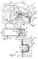
- Figure 1 is a perspective view of a hinge of the invention during its fitting to the refrigerator door;
- Figure 2 is a front view of the hinge of Figure 1; and
- Figure 3 is a section on the line 3-3 of Figure 1 with the hinge fitted to the door.
-
- With reference to said figures, a refrigerator, for example an upright refrigerator, comprises a usual cabinet 1 provided with food preservation compartments (not shown), and a usual door 2 provided with an outer shell (not shown), a
door liner 3 and abutment plates 4 (of which only one is shown in the figures).Usual insulation 5 is present between the shell and door liner. The cabinet and door are shown only schematically. The door moves relative to the cabinet 1 on hinges 6 (at least two), of which only one is shown in the figures, and which enable the door to be closed onto the cabinet 1 or be opened away from it. - Each
hinge 6 comprises anarm 10 having afirst end 11 fixed to an element (plate) 12 to be secured to the refrigerator cabinet 1 by screws or similar fixing means (not shown). Thearm 10 has asecond end 13 provided with athrough hole 14 to be mounted on one of twopins 15 facing it inside thecavity 16 of abox element 17 open on oneside 17A. This element is inserted into aseat 19 in thecorresponding abutment plate 4 and fixed in it by opposing lugs orteeth 21 which snap intoholes 22 provided in thewall 19A of theseat 19. Theelement 17 comprises a raisededge 20 which after insertion into theseat 19 rests against theabutment plate 4. - The
pins 15 are defined byparallel projections 23 extending fromopposing walls 24 of thecavity 16. These projections can be elastically forced apart and together to enable theend 13 of thehinge arm 10 to be mounted on them such that they cooperate by friction with thehole 14 in said arm, to allow correct movement of the door (slightly braked). - The hinge is assembled after the door has been constructed, this construction being totally independent thereof. The
arm 10 is insertion-fitted to thebox element 17 by inserting one of the twopins 15 into thehole 14 in thearm 10, depending on the hinge position (right or left, top or bottom) on the door. Preferably a ring 14A of self-lubricating material (for example nylon) is positioned in thehole 14 of thearm 10 to define a sort of bearing for the rotation of the arm relative to thepin 15. - After this assembly, the
element 12 is fixed to the cabinet 1 and theelement 17 is inserted into thedoor seat 19 until it snaps into secure connection to it. - The invention enables the door to be assembled in a simple manner without the hinge, which is fixed to the door only subsequently. The hinge also comprises a smaller number of components than known hinges.
Claims (6)
- A refrigerator, such as an upright refrigerator, having a cabinet (1), a door (2) and a hinge for the door (2) of the refrigerator the door comprising an outer shell, end abutment plates (4) and a door liner (3), usual insulation (5) being provided between the shell and door liner (3), said hinge comprising an arm (10) projecting from an element (12) for its fixing to said cabinet (1) and having a free end (13) provided with a through hole (14), said hinge further comprising a box member (17) to be inserted into a cavity (19) in a corresponding abutment plate (4) on the door, engagement means (15) being provided within the cavity (16) of this box member (17) to engage the free end (13) of the hinge arm (10) and connect this latter to said member (17) and hence to the door (2), but such as to enable it to rotate relative to said means (15), the box member (17) being open on one side (17A), through which the hinge arm (10) is inserted for coupling to the engagement means (15), characterised in that the engagement means (15) comprise two superposed spaced-apart connection elements projecting from opposing walls (24) of the cavity (16) of the box member (17), only one of said elements (15) being inserted into the hole (14) in the hinge arm (10), and cooperating with said arm (10) after its connection to said member (17).
- A refrigerator as claimed in claim 1, characterised in that each connection element (15) comprises two opposing parallel projections (23) extending from the corresponding wall (24) of the cavity (16) of the box member (17).
- A refrigerator as claimed in claim 1, characterised in that the box member (17) comprises fixing elements (21) which fix it into the seat (19) in the abutment plate (4) on the door (2).
- A refrigerator as claimed in claim 3, characterised in that the fixing elements (21) are teeth or lugs projecting from the box member (17) to cooperate with holes (22) provided in the wall (19A) of said seat.
- A refrigerator as claimed in claim 1, characterised in that the box member (17) comprises a raised edge (20) arranged to rest on the abutment plate (4) when said member (17) is in its seat (19).
- A refrigerator as claimed in claim 1, characterised in that an annular element (14A) of material of low friction coefficient is positioned in the hole (14) in the free end of the hinge arm (10) to become interposed between this arm (10) and the engagement means.
Applications Claiming Priority (2)
| Application Number | Priority Date | Filing Date | Title |
|---|---|---|---|
| IT1999MI000096 IT246535Y1 (en) | 1999-02-19 | 1999-02-19 | HINGE FOR A DOOR OF A REFRIGERATOR HAVING A REDUCED NUMBER OF COMPONENTS |
| ITMI990096U | 1999-02-19 |
Publications (2)
| Publication Number | Publication Date |
|---|---|
| EP1030139A1 EP1030139A1 (en) | 2000-08-23 |
| EP1030139B1 true EP1030139B1 (en) | 2004-10-27 |
Family
ID=11381553
Family Applications (1)
| Application Number | Title | Priority Date | Filing Date |
|---|---|---|---|
| EP20000102329 Expired - Lifetime EP1030139B1 (en) | 1999-02-19 | 2000-02-03 | Refrigerator door hinge with a reduced number of components |
Country Status (4)
| Country | Link |
|---|---|
| EP (1) | EP1030139B1 (en) |
| DE (1) | DE60015203T2 (en) |
| ES (1) | ES2228313T3 (en) |
| IT (1) | IT246535Y1 (en) |
Families Citing this family (2)
| Publication number | Priority date | Publication date | Assignee | Title |
|---|---|---|---|---|
| DE102008021337A1 (en) * | 2008-04-29 | 2009-11-05 | BSH Bosch und Siemens Hausgeräte GmbH | Hinge element and housing for a household appliance |
| KR101537600B1 (en) * | 2008-12-18 | 2015-07-20 | 엘지전자 주식회사 | Hinge assembly and refrigerator having the same |
Family Cites Families (5)
| Publication number | Priority date | Publication date | Assignee | Title |
|---|---|---|---|---|
| DE1276666B (en) * | 1963-02-08 | 1968-09-05 | Bosch Hausgeraete Gmbh | Fridge |
| DE3216962A1 (en) * | 1982-05-06 | 1983-11-10 | Licentia Patent-Verwaltungs-Gmbh, 6000 Frankfurt | Refrigerator |
| US5237723A (en) * | 1991-04-12 | 1993-08-24 | Itw Ltd. | Door hinge |
| US5220747A (en) * | 1992-10-27 | 1993-06-22 | General Electric Company | Refrigerator door biasing mechanism |
| US5355556A (en) * | 1993-01-26 | 1994-10-18 | Aircom Metal Products, Inc. | Enclosure having reversible door and hinge therefor |
-
1999
- 1999-02-19 IT IT1999MI000096 patent/IT246535Y1/en active
-
2000
- 2000-02-03 DE DE2000615203 patent/DE60015203T2/en not_active Expired - Fee Related
- 2000-02-03 EP EP20000102329 patent/EP1030139B1/en not_active Expired - Lifetime
- 2000-02-03 ES ES00102329T patent/ES2228313T3/en not_active Expired - Lifetime
Also Published As
| Publication number | Publication date |
|---|---|
| ITMI990096U1 (en) | 2000-08-19 |
| ES2228313T3 (en) | 2005-04-16 |
| DE60015203T2 (en) | 2005-11-10 |
| ITMI990096V0 (en) | 1999-02-19 |
| DE60015203D1 (en) | 2004-12-02 |
| EP1030139A1 (en) | 2000-08-23 |
| IT246535Y1 (en) | 2002-04-09 |
Similar Documents
| Publication | Publication Date | Title |
|---|---|---|
| US5265954A (en) | Refrigerator door hinge assembly | |
| US5870801A (en) | Screwless mounting for a door hinge plate of a refrigerator | |
| AU648010B2 (en) | Door hinge assembly | |
| US5975663A (en) | Articulating hinge covering door stop | |
| EP1329679B1 (en) | Refrigerator with door in door | |
| EP0994229B1 (en) | Snap hinge for supporting closure panel-like elements | |
| KR200170259Y1 (en) | Opening and closing device for ice discharge port of refrigerator | |
| CA2238461C (en) | Appliance shelving support system | |
| US20100084956A1 (en) | Refrigerator | |
| US4348068A (en) | Refrigerator casing | |
| US11168936B2 (en) | Storage bin assembly for a refrigerator | |
| EP1030139A1 (en) | Refrigerator door hinge with a reduced number of components | |
| US5930883A (en) | Cabinet system and method for manufacturing cabinets | |
| US5355556A (en) | Enclosure having reversible door and hinge therefor | |
| EP0668476B1 (en) | Method for incorporating hinges into refrigerators, freezers and the like | |
| KR102045274B1 (en) | Prefabricated storage box | |
| US20090021124A1 (en) | Cabinet with multi-compartment cabinet body | |
| JP3323370B2 (en) | Refrigerator top hinge structure | |
| KR100288943B1 (en) | Upper hinge assembly of refrigerator | |
| US3125390A (en) | Two door cabinet including improved door | |
| AU2018366073B2 (en) | Hinge and cabinet provided with a hinge | |
| US12590751B2 (en) | Domestic appliance having a symmetrical bracket of a hinge for a door | |
| US4797972A (en) | Sheet metal insert cup for cabinet hinges having a mortise centering mechanism | |
| JP2595167B2 (en) | Hinge | |
| CN219471794U (en) | Transmission with multiple locking functions |
Legal Events
| Date | Code | Title | Description |
|---|---|---|---|
| PUAI | Public reference made under article 153(3) epc to a published international application that has entered the european phase |
Free format text: ORIGINAL CODE: 0009012 |
|
| AK | Designated contracting states |
Kind code of ref document: A1 Designated state(s): DE ES FR GB IT |
|
| AX | Request for extension of the european patent |
Free format text: AL;LT;LV;MK;RO;SI |
|
| AKX | Designation fees paid | ||
| RBV | Designated contracting states (corrected) |
Designated state(s): DE ES FR GB IT |
|
| 17P | Request for examination filed |
Effective date: 20010208 |
|
| 17Q | First examination report despatched |
Effective date: 20030708 |
|
| GRAP | Despatch of communication of intention to grant a patent |
Free format text: ORIGINAL CODE: EPIDOSNIGR1 |
|
| GRAS | Grant fee paid |
Free format text: ORIGINAL CODE: EPIDOSNIGR3 |
|
| GRAA | (expected) grant |
Free format text: ORIGINAL CODE: 0009210 |
|
| AK | Designated contracting states |
Kind code of ref document: B1 Designated state(s): DE ES FR GB IT |
|
| REG | Reference to a national code |
Ref country code: GB Ref legal event code: FG4D |
|
| REF | Corresponds to: |
Ref document number: 60015203 Country of ref document: DE Date of ref document: 20041202 Kind code of ref document: P |
|
| REG | Reference to a national code |
Ref country code: ES Ref legal event code: FG2A Ref document number: 2228313 Country of ref document: ES Kind code of ref document: T3 |
|
| PLBE | No opposition filed within time limit |
Free format text: ORIGINAL CODE: 0009261 |
|
| STAA | Information on the status of an ep patent application or granted ep patent |
Free format text: STATUS: NO OPPOSITION FILED WITHIN TIME LIMIT |
|
| ET | Fr: translation filed | ||
| 26N | No opposition filed |
Effective date: 20050728 |
|
| PGFP | Annual fee paid to national office [announced via postgrant information from national office to epo] |
Ref country code: ES Payment date: 20090226 Year of fee payment: 10 |
|
| PGFP | Annual fee paid to national office [announced via postgrant information from national office to epo] |
Ref country code: GB Payment date: 20090227 Year of fee payment: 10 |
|
| PGFP | Annual fee paid to national office [announced via postgrant information from national office to epo] |
Ref country code: DE Payment date: 20090331 Year of fee payment: 10 Ref country code: IT Payment date: 20090224 Year of fee payment: 10 |
|
| PGFP | Annual fee paid to national office [announced via postgrant information from national office to epo] |
Ref country code: FR Payment date: 20090217 Year of fee payment: 10 |
|
| GBPC | Gb: european patent ceased through non-payment of renewal fee |
Effective date: 20100203 |
|
| REG | Reference to a national code |
Ref country code: FR Ref legal event code: ST Effective date: 20101029 |
|
| PG25 | Lapsed in a contracting state [announced via postgrant information from national office to epo] |
Ref country code: FR Free format text: LAPSE BECAUSE OF NON-PAYMENT OF DUE FEES Effective date: 20100301 |
|
| PG25 | Lapsed in a contracting state [announced via postgrant information from national office to epo] |
Ref country code: DE Free format text: LAPSE BECAUSE OF NON-PAYMENT OF DUE FEES Effective date: 20100901 |
|
| PG25 | Lapsed in a contracting state [announced via postgrant information from national office to epo] |
Ref country code: IT Free format text: LAPSE BECAUSE OF NON-PAYMENT OF DUE FEES Effective date: 20100203 Ref country code: GB Free format text: LAPSE BECAUSE OF NON-PAYMENT OF DUE FEES Effective date: 20100203 |
|
| REG | Reference to a national code |
Ref country code: ES Ref legal event code: FD2A Effective date: 20110407 |
|
| PG25 | Lapsed in a contracting state [announced via postgrant information from national office to epo] |
Ref country code: ES Free format text: LAPSE BECAUSE OF NON-PAYMENT OF DUE FEES Effective date: 20110328 |
|
| PG25 | Lapsed in a contracting state [announced via postgrant information from national office to epo] |
Ref country code: ES Free format text: LAPSE BECAUSE OF NON-PAYMENT OF DUE FEES Effective date: 20100204 |