EP1030083A2 - Parallel-axis gear differential with pinion mounted brake shoes - Google Patents
Parallel-axis gear differential with pinion mounted brake shoes Download PDFInfo
- Publication number
- EP1030083A2 EP1030083A2 EP00301250A EP00301250A EP1030083A2 EP 1030083 A2 EP1030083 A2 EP 1030083A2 EP 00301250 A EP00301250 A EP 00301250A EP 00301250 A EP00301250 A EP 00301250A EP 1030083 A2 EP1030083 A2 EP 1030083A2
- Authority
- EP
- European Patent Office
- Prior art keywords
- pinion
- gear
- support surface
- meshed
- housing
- Prior art date
- Legal status (The legal status is an assumption and is not a legal conclusion. Google has not performed a legal analysis and makes no representation as to the accuracy of the status listed.)
- Granted
Links
Images


Classifications
-
- F—MECHANICAL ENGINEERING; LIGHTING; HEATING; WEAPONS; BLASTING
- F16—ENGINEERING ELEMENTS AND UNITS; GENERAL MEASURES FOR PRODUCING AND MAINTAINING EFFECTIVE FUNCTIONING OF MACHINES OR INSTALLATIONS; THERMAL INSULATION IN GENERAL
- F16H—GEARING
- F16H57/00—General details of gearing
- F16H57/04—Features relating to lubrication or cooling or heating
-
- F—MECHANICAL ENGINEERING; LIGHTING; HEATING; WEAPONS; BLASTING
- F16—ENGINEERING ELEMENTS AND UNITS; GENERAL MEASURES FOR PRODUCING AND MAINTAINING EFFECTIVE FUNCTIONING OF MACHINES OR INSTALLATIONS; THERMAL INSULATION IN GENERAL
- F16H—GEARING
- F16H48/00—Differential gearings
- F16H48/20—Arrangements for suppressing or influencing the differential action, e.g. locking devices
- F16H48/28—Arrangements for suppressing or influencing the differential action, e.g. locking devices using self-locking gears or self-braking gears
- F16H48/285—Arrangements for suppressing or influencing the differential action, e.g. locking devices using self-locking gears or self-braking gears with self-braking intermeshing gears having parallel axes and having worms or helical teeth
Definitions
- This invention relates generally to differentials for use in automotive drivelines and, more particularly, to a parallel-axis gear differential having a planetary gearset equipped with brake shoes for improving gear alignment and increasing torque biasing.
- Parallel-axis gear differentials of the type used in automotive drivelines generally include a housing rotatively driven by the vehicle powertrain and a gearset supported in the housing which interconnects a pair of coaxial output shafts.
- the gearset typically includes a pair of side gears fixed to end portions of the output shafts and meshed pair sets of pinions respectively meshed with the side gears.
- the pinions are rotatably supported in longitudinal gear pockets formed in the housing.
- the gear pockets are circumferentially arranged to support the meshed sets of pinions for rotation about pinion axes that are parallel to the rotary axis shared by the side gears and the housing.
- a representative example of such a parallel-axis gear differential is shown in U.S. Pat. No. 5,711,737.
- 5,785,624 discloses the use of a supporting disc at one end of each pinion which bears against a journal post of the other pinion to support the ends of the meshed pinion set. Furthermore, U.S. Pat. No. 5,730,679 teaches of journalling an end shaft portion of each pinion in a support hole formed in the end walls of the housing for minimizing pinion tipping.
- some parallel-axis gear differentials are designed to permit limited movement of the pinions for increasing frictional resistance to speed differentiation.
- U.S. Pat. Nos. 5,415,599, 5,433,673 and 5,462,497 each disclose a parallel-axis gear differential equipped with a movable gear mounting structure (i.e., pivotable toggles or pedestals) having bearing surfaces which act on the outer diameter surface of adjacent pinions to apply a frictional braking force thereon.
- a movable gear mounting structure i.e., pivotable toggles or pedestals
- 5,443,431 shows a similar movable gear mounting structure mounted in a casing portion of the housing with friction wedges supported by the casing portion between adjacent meshed pairs of pinions for further increasing frictional resistance to differentiation.
- U.S. Pat. No. 3,375,736 teaches of a limited slip differential having support blocks aligned axially with the pinions. A coil spring is disposed therebetween for biasing the support blocks and pinions in opposite axial directions and into contact with a pair of laterally-spaced friction plates which, in turn, are fixed for rotation with the side gears, thereby providing a spring-biased limited slip function. Consequently, there remains a need in the differential art for a parallel-axis differential with an anti-tipping feature that improves pinion alignment stability in a simple and cost-effective manner.
- the anti-tipping mechanism is also operable to apply a frictional braking load on components of the gearset for increasing frictional resistance to speed differentiation.
- the present invention can be practiced as an improvement to parallel-axis gear differentials that include the conventional features of a housing rotatable about a common axis of a pair of output shafts, and a planetary gearset mounted in the housing for interconnecting the output shafts.
- the gearset includes a pair of side gears positioned within the housing and fixed for rotation with the output shafts, and two or more pairs of meshed pinions journally mounted in gear pockets formed in the housing, with each pinion having a gear segment meshed with a gear segment of the other pinion and with one of the side gears.
- the anti-tipping mechanism includes brake shoes that are journalled on integral stub shaft segments of the pinions.
- Each brake shoe has a first support surface which mates with the outer diameter surface of a corresponding side gear, a second support surface which mates with the outer diameter surface of the gear segment on the adjacent meshed pinion, and a third support surface which mates with the wall surface of the gear pocket.
- the brake shoes support the typically unsupported stub shaft segments of the pinions which, in conjunction with the length of meshed contact provided by the gear segments, acts to effectively support the pinions along their entire length.
- the interface between the stub shaft segment of the pinion and the brake shoe can be modified to include a cone clutch for generating supplemental braking forces in response to axial movement therebetween to further assist in increasing frictional resistance to differentiation.
- differential 10 for use in motor vehicle driveline applications will be described in sufficient detail to explain its novel and non-obvious structure, function, and features. While differential 10 is shown to be a parallel-axis gear differential of the type used in motor vehicle driveline applications, it is to be understood that the present invention is applicable for use with many variants of differential 10 and, as such, the particular structure shown is intended merely to be exemplary in nature.
- the motor vehicle driveline is shown to include an engine 12, a transmission 14, a rear axle assembly 16, and a propshaft 18 for supplying drive torque from transmission 14 to rear axle assembly 16.
- Rear axle assembly 16 includes differential 10 which is rotatably supported within a differential carrier 20.
- a ring gear 22 is fixed to a housing assembly 24 of differential 10 and is meshed with a drive pinion 26 that is fixed to a pinion shaft 28.
- pinion shaft 28 is connected to propshaft 18.
- engine power is transmitted by transmission 14 through propshaft 18, pinion shaft 28 and ring gear 22 for rotatively driving housing assembly 24.
- a planetary gearset 30 is supported within housing assembly 24 for operably interconnecting housing assembly 24 to a pair of axle shafts 32 and 34 which, in turn, are connected to drive wheels 36 and 38, respectively.
- housing assembly 24 is shown to include a drum housing 40 which defines an internal chamber 42 within which gearset 30 is supported. Housing assembly 24 also includes an end cap 44 which is press-fit to a radial flange segment 46 of drum housing 40 and secured thereto such as by fasteners (not shown) extending through aligned mounting apertures 44a and 46a. As is known, ring gear 22 is fixed to radial flange segment 46 to transfer rotary power (i.e., drive torque) to housing assembly 24. Housing assembly 24 also includes tubular axle trunions 50 and 52 which respectively define axially aligned axle openings 54 and 56 that communicate with chamber 42.
- Axle trunion 50 extends outwardly from the end cap 44 while axle trunion 52 extend outwardly from drum housing 40.
- Axle openings 54 and 56 are adapted to receive and rotatably support corresponding end segments of axle shafts 32 and 34 for rotation about a central rotary axis, denoted by construction line "A".
- housing assembly 24 of differential 10 is rotatably supported from carrier 20 by suitable axle bearings (not shown) for rotation about rotary axis "A”.
- annular sockets 58 and 60 are formed in axle openings 54 and 56 adjacent to chamber 42 for rotatably supporting components of gearset 30.
- differential assembly 10 includes a planetary gearset 30 which is operable for transferring drive torque from housing assembly 24 to axle shafts 32 and 34 in a manner facilitating speed differential and torque biasing therebetween.
- Gearset 30 is mounted in chamber 42 and includes a pair of helical side gears 62 and 64 having internal splines that are adapted to mesh with external splines on corresponding end segments of axle shafts 32 and 34.
- side gears 62 and 64 respectively include first axial hubs 62a and 64a which are seated in corresponding annular sockets 58 and 60.
- Side gears 62 and 64 also respectively include second axial hubs 62b and 64b.
- Retainers such as C-clips 66
- Gearset 30 further includes a spacer block assembly 68 for maintaining side gears 62 and 64 and axle shafts 32 and 34 in axially spaced relation relative to each other while preventing unintentional release of C-clips 66. Once installed, spacer block assembly 68 is free to rotate with respect to either axle shaft 32 and 34 and housing assembly 24.
- planetary gearset 30 also includes a set of first helical pinions 70 journally supported in first gear pockets 72 formed in drum housing 40 and a set of second helical pinions 74 journally supported in second gear pockets 76 formed in drum housing 40.
- differential 10 is shown to include two each of first pinions 70 and second pinions 74 arranged in meshed pairs, referred to as meshed pinion sets.
- Gear pockets 72 and 76 are elongated, longitudinal, partially cylindrical bores and are formed in paired overlapping sets such that they both communicate with chamber 42.
- gear pockets 72 and 76 are equidistant and circumferentially aligned so as to define pinion rotary axes "B" for first pinions 70 and rotary axes "C” for second pinions 74 that are parallel to the rotary axis "A" of housing assembly 24 and axle shafts 32 and 34.
- First gear pockets 72 are bores that extend from an end wall of drum housing 40 and which terminate with a radial end surface 80.
- second gear pockets 76 are bores that extend from the end wall of drum housing 40 and which terminate with a radial end surface 82.
- end cap 44 When end cap 44 is installed on drum housing 40, its inner face surface 84 encloses the open ends of pockets 72 and 76.
- At least one, and preferably two, large window apertures are formed in drum housing 40. The window apertures communicates with chamber 42 and portions of gear pockets 72 and 76 to permit access for installation of side gears 62 and 64 and C-clips 66.
- First pinions 70 are shown to include a long, larger diameter gear segment 70a and a short, smaller diameter stub shaft segment 70b. When installed in first gear pockets 72, first pinions 70 are arranged such that the teeth of gear segments 70a are meshed with the teeth of side gear 62 while their outer diameter tooth end surfaces are journally supported by the bearing wall surface of pockets 72.
- second pinions 74 are shown to include a long, larger diameter gear segment 74a and a short smaller diameter stub shaft 74b. When installed in second gear pockets 76, second pinions 74 are arranged such that the teeth of gear segments 74a are meshed with the teeth of side gear 64 while their outer diameter tooth end surfaces are journally supported by the bearing wall surface of second gear pockets 76.
- gear segment 70a of one of first pinions 70 also meshes with gear segment 74a of a corresponding one of second pinions 74.
- gear segments 70a and 74a are of an axial length to effectively maintain meshed engagement substantially along their entire length.
- planetary gearset 30 is equipped with an anti-tipping mechanism which functions to support stub shaft segments 70b on each of first pinions 70 against the bearing wall surface of its corresponding first gear pocket 72 and against the outer diameter tooth end surfaces of side gear 64 and gear segment 74a of its meshed second pinion 74.
- the anti-tipping mechanism is similarly employed to support stub shaft segment 74b on each of second pinions 74 against the bearing wall surface of its corresponding second gear pocket 76 and against the outer diameter tooth end surfaces of side gear 62 and gear segment 70a of its meshed first pinion 70.
- the anti-tipping feature is provided by a set of support members, hereinafter referred to as brake shoes 90, that are mounted on pinion stub shaft segments 70b, 74b prior to installation of pinions 70, 74 into gear pockets 72,76.
- brake shoes 90 can be inserted into gear pockets 72, 76 prior to installation of pinions 70, 74 therein.
- Brake shoes 90 include an axial aperture 92 that is sized to journally support pinion shaft segments 70b and 74b while limiting radial deflection thereof.
- Each brake shoe 90 has a first support surface 94, a second support surface 96, and a third support surface 98.
- First support surface 94 is arcuate and is configured to rotationally support the outer diameter tooth end surface of the corresponding one of side gears 62 and 64.
- Second support surface 96 is arcuate and is configured to rotationally support the outer diameter tooth end surface of corresponding pinion gear segment 70a, 74a.
- third support surface 98 is arcuate and is configured such that it is supported by the complimentary bearing wall surface of the corresponding gear pocket 72, 76.
- Brake shoes 90 have an axial length selected to support stub shafts 70b, 74b substantially along their entire length while permitting limited axial sliding movement of brake shoes 90 in gear pockets 70, 72 relative to the pinions. Under normal circumstances, this lateral clearance prevents binding of the pinions. However, axial movement of the pinions due to thrust loads will cause frictional engagement between face surfaces 100 and 102 of brake shoes 90 and adjacent pinion end surfaces 70c and 74c, thereby increasing the torque bias ratio of differential 10.
- pinion stub shaft 70b' of pinion 70' is shown to be frusto-conically tapered in contrast to the right cylindrical stub shaft 70b of pinion 70 previously disclosed.
- Pinion stub shaft 70b' is tapered with a larger diameter proximate to gear segment 70a and a small diameter at its distal end.
- aperture 92' in brake shoe 90' is frusto-conically tapered to mate with tapered pinion stub shaft 70b'.
- FIG. 6 illustrates integration of a clutch cone between the pinion shaft and the brake shoe for providing additional resistance to differentiation in response to axial travel of the pinion relative to the brake shoe.
- the modified brake shoe 90' could likewise be used with modified second pinions having a tapered stub shaft segment.
Landscapes
- Engineering & Computer Science (AREA)
- General Engineering & Computer Science (AREA)
- Mechanical Engineering (AREA)
- Retarders (AREA)
- Braking Arrangements (AREA)
Abstract
Description
- This invention relates generally to differentials for use in automotive drivelines and, more particularly, to a parallel-axis gear differential having a planetary gearset equipped with brake shoes for improving gear alignment and increasing torque biasing.
- Parallel-axis gear differentials of the type used in automotive drivelines generally include a housing rotatively driven by the vehicle powertrain and a gearset supported in the housing which interconnects a pair of coaxial output shafts. The gearset typically includes a pair of side gears fixed to end portions of the output shafts and meshed pair sets of pinions respectively meshed with the side gears. The pinions are rotatably supported in longitudinal gear pockets formed in the housing. The gear pockets are circumferentially arranged to support the meshed sets of pinions for rotation about pinion axes that are parallel to the rotary axis shared by the side gears and the housing. A representative example of such a parallel-axis gear differential is shown in U.S. Pat. No. 5,711,737.
- As is known, during high torque conditions the gear loading may cause the ends of the pinions to move radially (i.e., "end tipping") which, in turn, causes the pinions to aggressively engage the bearing wall surfaces of the gear pockets, thereby potentially degrading the durability of the differential. In addition, such tipping often results in misalignment of the gear contact surfaces which can detrimentally impact tooth life and the efficiency of the gearset. In an effort to improve pinion alignment stability in parallel-axis gear differentials, various alternative support structures have been proposed. For example, U.S. Pat. No. 5,658,214 discloses the use of bearing plates to support the opposite ends of the intermeshed pinion set. In an alternative arrangement, U.S. Pat. No. 5,785,624 discloses the use of a supporting disc at one end of each pinion which bears against a journal post of the other pinion to support the ends of the meshed pinion set. Furthermore, U.S. Pat. No. 5,730,679 teaches of journalling an end shaft portion of each pinion in a support hole formed in the end walls of the housing for minimizing pinion tipping.
- In addition to the pinion support arrangements described above, some parallel-axis gear differentials are designed to permit limited movement of the pinions for increasing frictional resistance to speed differentiation. For example, U.S. Pat. Nos. 5,415,599, 5,433,673 and 5,462,497 each disclose a parallel-axis gear differential equipped with a movable gear mounting structure (i.e., pivotable toggles or pedestals) having bearing surfaces which act on the outer diameter surface of adjacent pinions to apply a frictional braking force thereon. In a further modified form, U.S. Pat. No. 5,443,431 shows a similar movable gear mounting structure mounted in a casing portion of the housing with friction wedges supported by the casing portion between adjacent meshed pairs of pinions for further increasing frictional resistance to differentiation. Finally, U.S. Pat. No. 3,375,736 teaches of a limited slip differential having support blocks aligned axially with the pinions. A coil spring is disposed therebetween for biasing the support blocks and pinions in opposite axial directions and into contact with a pair of laterally-spaced friction plates which, in turn, are fixed for rotation with the side gears, thereby providing a spring-biased limited slip function. Consequently, there remains a need in the differential art for a parallel-axis differential with an anti-tipping feature that improves pinion alignment stability in a simple and cost-effective manner.
- Thus, it is an object of the present invention to provide a parallel-axis differential having a planetary gearset equipped with anti-tipping mechanism for supporting the pinions along their entire length.
- As a related object of the present invention, the anti-tipping mechanism is also operable to apply a frictional braking load on components of the gearset for increasing frictional resistance to speed differentiation.
- Accordingly, the present invention can be practiced as an improvement to parallel-axis gear differentials that include the conventional features of a housing rotatable about a common axis of a pair of output shafts, and a planetary gearset mounted in the housing for interconnecting the output shafts. The gearset includes a pair of side gears positioned within the housing and fixed for rotation with the output shafts, and two or more pairs of meshed pinions journally mounted in gear pockets formed in the housing, with each pinion having a gear segment meshed with a gear segment of the other pinion and with one of the side gears. The anti-tipping mechanism includes brake shoes that are journalled on integral stub shaft segments of the pinions. Each brake shoe has a first support surface which mates with the outer diameter surface of a corresponding side gear, a second support surface which mates with the outer diameter surface of the gear segment on the adjacent meshed pinion, and a third support surface which mates with the wall surface of the gear pocket. Thus, the brake shoes support the typically unsupported stub shaft segments of the pinions which, in conjunction with the length of meshed contact provided by the gear segments, acts to effectively support the pinions along their entire length.
- As an optional feature, the interface between the stub shaft segment of the pinion and the brake shoe can be modified to include a cone clutch for generating supplemental braking forces in response to axial movement therebetween to further assist in increasing frictional resistance to differentiation.
- Further areas of applicability of the present invention will become apparent from the detailed description provided hereinafter, it should be understood, however, that the detailed description and specific examples, while indicating preferred embodiments of the invention, is intended for purposes of illustration only since various changes and modifications within the scope and spirit of the invention will become apparent to those skilled in the art from this detailed description.
- The present invention will become more fully understood from the detailed description and the accompanying drawings, wherein:
- FIG. 1 is a schematic illustration of an exemplary driveline for a motor vehicle equipped with a parallel-axis gear differential of the present invention;
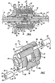
- FIG. 2 is a sectional view of the parallel-axis gear differential of the present invention;
- FIG. 3 is an assembled perspective view of the planetary gearset associated with the parallel-axis gear differential shown in FIG. 2;
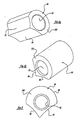
- FIGS. 4 and 4B are perspective views of the brake shoe associated with the gearset shown in FIG. 3;
- FIG. 5 is an end view of the brake shoes shown in FIG. 4; and
- FIG. 6 is a partial sectional view showing an alternative interface between the pinion and the brake shoe.
-
- With reference to the drawings, a
differential 10 for use in motor vehicle driveline applications will be described in sufficient detail to explain its novel and non-obvious structure, function, and features. Whiledifferential 10 is shown to be a parallel-axis gear differential of the type used in motor vehicle driveline applications, it is to be understood that the present invention is applicable for use with many variants ofdifferential 10 and, as such, the particular structure shown is intended merely to be exemplary in nature. - Prior to the description of the components associated with
differential 10, an exemplary driveline for a motor vehicle equipped withdifferential 10 will be explained with particular reference to FIG. 1. Specifically, the motor vehicle driveline is shown to include anengine 12, atransmission 14, arear axle assembly 16, and apropshaft 18 for supplying drive torque fromtransmission 14 torear axle assembly 16.Rear axle assembly 16 includesdifferential 10 which is rotatably supported within adifferential carrier 20. Aring gear 22 is fixed to ahousing assembly 24 ofdifferential 10 and is meshed with adrive pinion 26 that is fixed to apinion shaft 28. As is conventional,pinion shaft 28 is connected topropshaft 18. As such, engine power is transmitted bytransmission 14 throughpropshaft 18,pinion shaft 28 andring gear 22 for rotativelydriving housing assembly 24. Finally, aplanetary gearset 30 is supported withinhousing assembly 24 for operably interconnectinghousing assembly 24 to a pair ofaxle shafts drive wheels - With particular reference to FIGS. 2 through 5, a first embodiment of
differential 10 is shown in greater detail. In particular,housing assembly 24 is shown to include adrum housing 40 which defines an internal chamber 42 within whichgearset 30 is supported.Housing assembly 24 also includes anend cap 44 which is press-fit to a radial flange segment 46 ofdrum housing 40 and secured thereto such as by fasteners (not shown) extending through alignedmounting apertures ring gear 22 is fixed to radial flange segment 46 to transfer rotary power (i.e., drive torque) tohousing assembly 24.Housing assembly 24 also includestubular axle trunions axle openings trunion 50 extends outwardly from theend cap 44 whileaxle trunion 52 extend outwardly fromdrum housing 40.Axle openings axle shafts housing assembly 24 ofdifferential 10 is rotatably supported fromcarrier 20 by suitable axle bearings (not shown) for rotation about rotary axis "A". In addition,annular sockets 58 and 60 are formed inaxle openings gearset 30. - As noted,
differential assembly 10 includes aplanetary gearset 30 which is operable for transferring drive torque fromhousing assembly 24 toaxle shafts Gearset 30 is mounted in chamber 42 and includes a pair of helical side gears 62 and 64 having internal splines that are adapted to mesh with external splines on corresponding end segments ofaxle shafts axial hubs annular sockets 58 and 60. Side gears 62 and 64 also respectively include secondaxial hubs 62b and 64b. Retainers, such as C-clips 66, are retained betweenshaft grooves axial hubs 62b, 64b for axially positioning and restraining side gears 62 and 64 between end wall surfaces ofhousing assembly 24 and the end segments ofaxle shafts Gearset 30 further includes aspacer block assembly 68 for maintaining side gears 62 and 64 andaxle shafts spacer block assembly 68 is free to rotate with respect to eitheraxle shaft housing assembly 24. - As best seen from FIG. 2,
planetary gearset 30 also includes a set of firsthelical pinions 70 journally supported in first gear pockets 72 formed indrum housing 40 and a set of secondhelical pinions 74 journally supported in second gear pockets 76 formed indrum housing 40. While not limited thereto, differential 10 is shown to include two each offirst pinions 70 andsecond pinions 74 arranged in meshed pairs, referred to as meshed pinion sets. Gear pockets 72 and 76 are elongated, longitudinal, partially cylindrical bores and are formed in paired overlapping sets such that they both communicate with chamber 42. In addition, gear pockets 72 and 76 are equidistant and circumferentially aligned so as to define pinion rotary axes "B" forfirst pinions 70 and rotary axes "C" forsecond pinions 74 that are parallel to the rotary axis "A" ofhousing assembly 24 andaxle shafts drum housing 40 and which terminate with aradial end surface 80. Similarly, second gear pockets 76 are bores that extend from the end wall ofdrum housing 40 and which terminate with aradial end surface 82. Whenend cap 44 is installed ondrum housing 40, itsinner face surface 84 encloses the open ends ofpockets drum housing 40. The window apertures communicates with chamber 42 and portions of gear pockets 72 and 76 to permit access for installation of side gears 62 and 64 and C-clips 66. - First pinions 70 are shown to include a long, larger
diameter gear segment 70a and a short, smaller diameterstub shaft segment 70b. When installed in first gear pockets 72, first pinions 70 are arranged such that the teeth ofgear segments 70a are meshed with the teeth ofside gear 62 while their outer diameter tooth end surfaces are journally supported by the bearing wall surface ofpockets 72. Likewise,second pinions 74 are shown to include a long, largerdiameter gear segment 74a and a short smallerdiameter stub shaft 74b. When installed in second gear pockets 76, second pinions 74 are arranged such that the teeth ofgear segments 74a are meshed with the teeth ofside gear 64 while their outer diameter tooth end surfaces are journally supported by the bearing wall surface of second gear pockets 76. Sincepinions gear segment 70a of one offirst pinions 70 also meshes withgear segment 74a of a corresponding one of second pinions 74. Preferably,gear segments - According to the present invention,
planetary gearset 30 is equipped with an anti-tipping mechanism which functions to supportstub shaft segments 70b on each offirst pinions 70 against the bearing wall surface of its correspondingfirst gear pocket 72 and against the outer diameter tooth end surfaces ofside gear 64 andgear segment 74a of its meshedsecond pinion 74. The anti-tipping mechanism is similarly employed to supportstub shaft segment 74b on each ofsecond pinions 74 against the bearing wall surface of its correspondingsecond gear pocket 76 and against the outer diameter tooth end surfaces ofside gear 62 andgear segment 70a of its meshedfirst pinion 70. By supportingshaft segments - The anti-tipping feature is provided by a set of support members, hereinafter referred to as
brake shoes 90, that are mounted on pinionstub shaft segments pinions brake shoes 90 can be inserted into gear pockets 72, 76 prior to installation ofpinions Brake shoes 90 include anaxial aperture 92 that is sized to journally supportpinion shaft segments brake shoe 90 has afirst support surface 94, asecond support surface 96, and athird support surface 98.First support surface 94 is arcuate and is configured to rotationally support the outer diameter tooth end surface of the corresponding one of side gears 62 and 64.Second support surface 96 is arcuate and is configured to rotationally support the outer diameter tooth end surface of correspondingpinion gear segment third support surface 98 is arcuate and is configured such that it is supported by the complimentary bearing wall surface of thecorresponding gear pocket pinion gear segments brake shoes 90 will result in frictional engagement therebetween which generates a braking force for limiting speed differentiation therebetween. This braking feature also results in increased torque bias fordifferential 10.Brake shoes 90 have an axial length selected to supportstub shafts brake shoes 90 in gear pockets 70, 72 relative to the pinions. Under normal circumstances, this lateral clearance prevents binding of the pinions. However, axial movement of the pinions due to thrust loads will cause frictional engagement between face surfaces 100 and 102 ofbrake shoes 90 and adjacent pinion end surfaces 70c and 74c, thereby increasing the torque bias ratio of differential 10. - With particular reference now to FIG. 6, a modified construction of the interface between the pinion stub shaft segment and the brake shoe are shown. Specifically,
pinion stub shaft 70b' of pinion 70' is shown to be frusto-conically tapered in contrast to the rightcylindrical stub shaft 70b ofpinion 70 previously disclosed.Pinion stub shaft 70b' is tapered with a larger diameter proximate to gearsegment 70a and a small diameter at its distal end. Likewise, aperture 92' in brake shoe 90' is frusto-conically tapered to mate with taperedpinion stub shaft 70b'. - With such a tapered socket-type arrangement, axial movement of pinion 70' toward brake shoe 90' causes frictional engagement between tapered
pinion stub shaft 70b' and the tapered wall surface of brake shoe aperture 92'. Since brake shoe 90' is prevented from rotating due to its first and second support surfaces 94 and 96 respectively mating withside gear 64 andgear segment 74a, such frictional engagement functions to brake rotation of pinion 70'. Thus, FIG. 6 illustrates integration of a clutch cone between the pinion shaft and the brake shoe for providing additional resistance to differentiation in response to axial travel of the pinion relative to the brake shoe. Obviously the modified brake shoe 90' could likewise be used with modified second pinions having a tapered stub shaft segment. - While the invention has been described in the specification and illustrated in the drawings with reference to different embodiments, it will be understood by those skilled in the art that various changes may be made and equivalents may be substituted for elements thereof without departing from the scope of the invention as defined in the claims. In addition, many modifications may be made to adapt a particular situation or material to the teachings of the invention without departing from the essential scope thereof. Therefore, it is intended that the invention not be limited to the particular embodiments illustrated by the drawings and described in the specification as the best mode presently contemplated for carrying out this invention, but that the invention will include any embodiments falling within the description of the appended claims.
Claims (11)
- A differential interconnecting a pair of shafts, comprising:a housing rotatable about a common axis of the output shafts and defining an internal chamber, first and second pinion pockets communicating with said chamber, and openings for receiving end segments of the shafts extending into said chamber;a first side gear rotatably supported in said chamber and adapted to be fixed for rotation with one of the shafts;a second side gear rotatably supported in said chamber and adapted to be fixed for rotation with the other of the shafts;a first pinion having a first gear segment and a first shaft segment, said first pinion is rotatably supported in said first pinion pocket such that said first gear segment is meshed with said first side gear;a second pinion having a second gear segment and a second shaft segment, said second pinion is rotatably supported in said second pinion pocket such that said second gear segment is meshed with said second side gear and said first gear segment; anda brake shoe encircling said first shaft segment and having first, second and third support surfaces, said first support surface mating with an outer surface of said first side gear, said second support surface mating with an outer surface of said second gear segment, and said third support surface mating with a wall surface of said first pinion pocket.
- The differential of claim 1 further comprising a brake shoe encircling said second shaft segment and having its first support surface mating with an outer surface of said second side gear, its second support surface mating with an outer surface of said first gear segment, and its third support surface mating with a wall surface of said second pinion pocket.
- The differential of claim 1 or claim 2 wherein said first and second pinions have rotary axes aligned in parallel to the common axis of said housing and the shafts.
- The differential of any one of the preceding claims further comprising additional paired sets of first and second pinion pockets formed circumferentially in said housing, and a corresponding number of first and second pinions installed in said additional paired sets of pinion pockets.
- The differential of any one of the preceding claims, wherein said first shaft segment of said first pinion is journalled in an aperture formed in said brake shoe.
- A differential comprising:a housing having an interior chamber, first and second openings adapted for supporting end segments of first and second shafts for rotation about a common shaft axis, at least two pinion bore sets each having a first pinion pocket extending along an axis that is parallel to said shaft axis and a second pinion pocket overlapping said first pinion pocket and extending along an axis that is parallel to said shaft axis and said first pinion pocket axis;a gearset having first and second side gears rotatably supported in said interior chamber that are adapted to be fixed for rotation with the first and second shafts, and at least two meshed pinion sets each having a first pinion mounted in one of said first pinion pockets that is meshed with said first side gear, and a second pinion mounted in one of said second pinion pockets that is meshed with said second side gear; andbrake shoes axially aligned with said first pinions and having an aperture journally supporting a shaft segment of said first pinion, a first support surface mating with an outer surface of said first side gear, a second support surface mating with an outer surface of a corresponding second pinion of said meshed pinion set, and a third support surface mating with an inner wall surface of said first pinion pocket.
- The differential of claim 6 further comprising additional brake shoes aligned with said second pinions and having said apertures journally supporting a shaft segment of said second pinions, and wherein said first support surface of said brake shoe mates with an outer surface of said second side gear, said second support surface of said brake shoes mates with an outer surface of a corresponding first pinion, and said third support surface of said brake shoe mates with an inner wall surface of said second pinion pocket.
- A differential comprising:a differential housing defining an internal chamber, a first axle opening extending from said chamber through a first end wall of said housing, a second axle opening extending from said chamber through a second end wall of said housing, at least two pinion bore sets each having first and second overlapping pinion pockets extending across said chamber, a first socket disposed between said first axle opening and said chamber, and a second socket disposed between said second axle opening and said chamber;a first side gear positioned within said chamber and seated in said first socket;a second side gear positioned within said chamber and seated in said second socket;at least two meshed pinion sets each having a first pinion disposed within one of said first pinion pockets and meshed with said first side gear and a second pinion disposed within a corresponding one of said second pinion pockets and meshed with said second side gear and said first pinion gear; andbrake shoes axially aligned with said first pinions and having an aperture journally supporting an integral shaft segment at one end of said first pinion, said brake shoes further including a first support surface mating with an outer surface of said first side gear, a second support surface mating with an outer surface of a corresponding second pinion of said meshed pinion set, and a third support surface mating with an inner wall surface of said first pinion pocket.
- The differential of any one of claims 5 to 8, wherein said aperture is tapered and said first shaft segment is matingly tapered to define a cone clutch that is operable to generate a frictional braking force for limiting rotation of said first pinion relative to said brake shoe in response to relative axial movement therebetween.
- The differential of any one of the preceding claims, wherein said housing includes a drum housing with said first and second pinion pockets extending longitudinally from an end surface, and an end cap mating with said end surface of said drum housing to enclose open ends of said first and second pinion pockets.
- A differential comprising:a housing having an Interior chamber and first and second openings adapted for supporting end segments of first and second shafts for rotation about a common shaft axis, said housing also having at least two pinion bore sets with each set including a first pinion pocket extending along an axis that is parallel to said shaft axis and a second pinion pocket overlapping said first pinion pocket and extending along an axis that is parallel to said shaft axis and said first pinion pocket axis;a gearset having first and second side gears rotatably supported in said interior chamber that are adapted to be fixed for rotation with the first and second shafts, and at least two meshed pinion sets each having a first pinion mounted in one of said first pinion pockets that is meshed with said first side gear, and a second pinion mounted in one of said second pinion pockets that is meshed with said second side gear;A first set of brake shoes axially aligned with said first pinions and each having an aperture journally supporting a shaft segment of said first pinion, a first support surface mating with an outer surface of said first side gear, a second support surface mating with an outer surface of a corresponding second pinion of said meshed pinion set, and a third support surface mating with an inner wall surface of said first pinion pocket; anda second set of brake shoes axially aligned with said second pinions and each having its aperture journally supporting a shaft segment of said second pinion, its first support surface mating with an outer surface of said second side gear, its second support surface mating with an outer surface of a corresponding first pinion of said meshed pinion set, and its third support surface mating with an inner wall surface of said second pinion pocket.
Applications Claiming Priority (2)
| Application Number | Priority Date | Filing Date | Title |
|---|---|---|---|
| US09/251,319 US6013004A (en) | 1999-02-17 | 1999-02-17 | Parallel-axis gear differential with pinion mounted brake shoes |
| US251319 | 1999-02-17 |
Publications (3)
| Publication Number | Publication Date |
|---|---|
| EP1030083A2 true EP1030083A2 (en) | 2000-08-23 |
| EP1030083A3 EP1030083A3 (en) | 2003-03-19 |
| EP1030083B1 EP1030083B1 (en) | 2005-02-02 |
Family
ID=22951433
Family Applications (1)
| Application Number | Title | Priority Date | Filing Date |
|---|---|---|---|
| EP00301250A Expired - Lifetime EP1030083B1 (en) | 1999-02-17 | 2000-02-17 | Parallel-axis gear differential with pinion mounted brake shoes |
Country Status (8)
| Country | Link |
|---|---|
| US (1) | US6013004A (en) |
| EP (1) | EP1030083B1 (en) |
| JP (1) | JP4558126B2 (en) |
| BR (1) | BR0000484A (en) |
| CA (1) | CA2298818A1 (en) |
| DE (1) | DE60017813T2 (en) |
| ES (1) | ES2235773T3 (en) |
| MX (1) | MXPA00001658A (en) |
Cited By (1)
| Publication number | Priority date | Publication date | Assignee | Title |
|---|---|---|---|---|
| EP1052430A3 (en) * | 1999-05-13 | 2002-05-15 | American Axle & Manufacturing Inc. | Differential casing |
Families Citing this family (16)
| Publication number | Priority date | Publication date | Assignee | Title |
|---|---|---|---|---|
| US6325737B1 (en) * | 2000-03-22 | 2001-12-04 | American Axle & Manufacturing, Inc. | Helical gear differential with geared lube pump |
| US6325738B1 (en) * | 2000-04-26 | 2001-12-04 | Illinois Tool Works Inc. | Limited slip differential |
| US6471618B2 (en) * | 2000-05-16 | 2002-10-29 | Visteon Global Technologies, Inc. | Torque biasing device, speed matching device and control methods |
| US6830530B2 (en) * | 2002-09-25 | 2004-12-14 | Visteon Global Technologies, Inc. | Torque biasing planetary differential |
| US6958030B2 (en) * | 2003-09-29 | 2005-10-25 | American Axle & Manufacturing, Inc. | Electromagnetic locking differential assembly |
| US7022040B2 (en) * | 2003-09-29 | 2006-04-04 | American Axle & Manufacturing, Inc. | Locking differential with electromagnetic actuator |
| US7602271B2 (en) | 2006-08-21 | 2009-10-13 | American Axle & Manufacturing, Inc. | Electronically actuated apparatus using solenoid actuator with integrated sensor |
| US7572202B2 (en) * | 2007-01-31 | 2009-08-11 | American Axle & Manufacturing, Inc. | Electronic locking differential with direct locking state detection system |
| US7682280B2 (en) * | 2007-06-19 | 2010-03-23 | American Axle & Manufacturing, Inc. | Differential assembly with preload adjustment mechanism |
| US8157693B2 (en) | 2007-06-19 | 2012-04-17 | American Axle & Manufacturing, Inc. | Helical differential assembly with preloaded adjustment mechanism |
| US7837588B2 (en) * | 2007-07-20 | 2010-11-23 | American Axle & Manufacturing, Inc. | Pre-load mechanism for helical gear differential |
| US9347542B2 (en) * | 2008-09-30 | 2016-05-24 | American Axle & Manufacturing, Inc. | Parallel-axis helical differential assembly |
| US8713984B2 (en) | 2011-01-13 | 2014-05-06 | David Wilson, Jr. | Multiple mode, bi-directional universal bending apparatus |
| WO2012135738A2 (en) | 2011-04-01 | 2012-10-04 | American Axle & Manufacturing, Inc. | Differential assembly |
| CN103335087A (en) * | 2013-07-19 | 2013-10-02 | 李国铭 | Oil pressure type limited slip differential |
| CN110735905A (en) * | 2019-10-29 | 2020-01-31 | 安徽工程大学 | differential transmission device with active high speed regulation |
Citations (9)
| Publication number | Priority date | Publication date | Assignee | Title |
|---|---|---|---|---|
| US3375736A (en) | 1966-09-15 | 1968-04-02 | Illinois Tool Works | Differential mechanism |
| US5415599A (en) | 1993-05-06 | 1995-05-16 | Zexel-Gleason Usa, Inc. | Gear mounting system for differential |
| US5433673A (en) | 1993-05-06 | 1995-07-18 | Zexel Torsen Inc. | Differential with pivotable gear mountings |
| US5443431A (en) | 1993-10-13 | 1995-08-22 | Zexel-Gleason Usa, Inc. | Differential with friction-enhancing wedge |
| US5462497A (en) | 1993-05-06 | 1995-10-31 | Zexel Torsen Inc | Controllable parallel axis differential |
| US5658214A (en) | 1995-02-10 | 1997-08-19 | Gkn Viscodrive Gmbh | Differential drive |
| US5711737A (en) | 1994-09-11 | 1998-01-27 | Tochigi Fuji Sangyo Kabushiki Kaisha | Differential apparatus |
| US5730679A (en) | 1994-11-04 | 1998-03-24 | Zexel Corporation | Parallel-axis differential |
| US5785624A (en) | 1995-07-21 | 1998-07-28 | Mayr; Nikolaus | Differential drive with supporting means for differential gears |
Family Cites Families (8)
| Publication number | Priority date | Publication date | Assignee | Title |
|---|---|---|---|---|
| DE4013197C1 (en) * | 1990-04-25 | 1992-02-06 | Viscodrive Gmbh, 5204 Lohmar, De | |
| US5221238A (en) * | 1992-08-21 | 1993-06-22 | Dyneet Corporation | Differential with preload means and sectional spacer means |
| JPH07317878A (en) * | 1994-05-30 | 1995-12-08 | Tochigi Fuji Ind Co Ltd | Differential device |
| US5492510A (en) * | 1994-10-21 | 1996-02-20 | Zexel Torsen Inc. | Differential with extended planet gears having multiple meshing portions |
| US5733216A (en) * | 1995-03-08 | 1998-03-31 | Zexel Torsen Inc. | Thrust-block for C-clip differential |
| IT1275590B1 (en) * | 1995-07-21 | 1997-08-06 | Gkn Birfield Ag | DIFFERENTIAL WITH SATELLITES WITH ROUNDED SUPPORT PINS |
| DE19603264C2 (en) * | 1996-01-30 | 1999-01-07 | Gkn Viscodrive Gmbh | Differential gear with internal support of the differential gears |
| JP2602993Y2 (en) * | 1998-05-19 | 2000-02-07 | 栃木富士産業株式会社 | Differential device |
-
1999
- 1999-02-17 US US09/251,319 patent/US6013004A/en not_active Expired - Lifetime
-
2000
- 2000-02-16 CA CA002298818A patent/CA2298818A1/en not_active Abandoned
- 2000-02-17 DE DE60017813T patent/DE60017813T2/en not_active Expired - Lifetime
- 2000-02-17 EP EP00301250A patent/EP1030083B1/en not_active Expired - Lifetime
- 2000-02-17 MX MXPA00001658A patent/MXPA00001658A/en active IP Right Grant
- 2000-02-17 JP JP2000040024A patent/JP4558126B2/en not_active Expired - Lifetime
- 2000-02-17 BR BR0000484-7A patent/BR0000484A/en not_active IP Right Cessation
- 2000-02-17 ES ES00301250T patent/ES2235773T3/en not_active Expired - Lifetime
Patent Citations (9)
| Publication number | Priority date | Publication date | Assignee | Title |
|---|---|---|---|---|
| US3375736A (en) | 1966-09-15 | 1968-04-02 | Illinois Tool Works | Differential mechanism |
| US5415599A (en) | 1993-05-06 | 1995-05-16 | Zexel-Gleason Usa, Inc. | Gear mounting system for differential |
| US5433673A (en) | 1993-05-06 | 1995-07-18 | Zexel Torsen Inc. | Differential with pivotable gear mountings |
| US5462497A (en) | 1993-05-06 | 1995-10-31 | Zexel Torsen Inc | Controllable parallel axis differential |
| US5443431A (en) | 1993-10-13 | 1995-08-22 | Zexel-Gleason Usa, Inc. | Differential with friction-enhancing wedge |
| US5711737A (en) | 1994-09-11 | 1998-01-27 | Tochigi Fuji Sangyo Kabushiki Kaisha | Differential apparatus |
| US5730679A (en) | 1994-11-04 | 1998-03-24 | Zexel Corporation | Parallel-axis differential |
| US5658214A (en) | 1995-02-10 | 1997-08-19 | Gkn Viscodrive Gmbh | Differential drive |
| US5785624A (en) | 1995-07-21 | 1998-07-28 | Mayr; Nikolaus | Differential drive with supporting means for differential gears |
Cited By (1)
| Publication number | Priority date | Publication date | Assignee | Title |
|---|---|---|---|---|
| EP1052430A3 (en) * | 1999-05-13 | 2002-05-15 | American Axle & Manufacturing Inc. | Differential casing |
Also Published As
| Publication number | Publication date |
|---|---|
| DE60017813D1 (en) | 2005-03-10 |
| US6013004A (en) | 2000-01-11 |
| MXPA00001658A (en) | 2001-11-01 |
| DE60017813T2 (en) | 2006-02-02 |
| EP1030083A3 (en) | 2003-03-19 |
| BR0000484A (en) | 2000-11-14 |
| ES2235773T3 (en) | 2005-07-16 |
| JP4558126B2 (en) | 2010-10-06 |
| EP1030083B1 (en) | 2005-02-02 |
| JP2000240759A (en) | 2000-09-05 |
| CA2298818A1 (en) | 2000-08-17 |
Similar Documents
| Publication | Publication Date | Title |
|---|---|---|
| US6013004A (en) | Parallel-axis gear differential with pinion mounted brake shoes | |
| US7976423B2 (en) | Pre-load mechanism for helical gear differential | |
| US6053838A (en) | Helical differential assembly | |
| US6699154B2 (en) | Differential gear assembly | |
| US7232399B2 (en) | Differential assembly | |
| US6863634B2 (en) | Tandem axle power divider assembly with inboard slip driveshaft connection | |
| US8157693B2 (en) | Helical differential assembly with preloaded adjustment mechanism | |
| US5342256A (en) | Differential gear system | |
| US7611437B2 (en) | Spacer pin arrangement for helical gear differential | |
| US6182808B1 (en) | Viscous actuated ball ramp clutch having through shaft capability | |
| CA2279377A1 (en) | Differential with shaft locking mechanism | |
| JP5021343B2 (en) | Double differential device | |
| US5273498A (en) | Differential mechanism | |
| US6475091B1 (en) | Linking structure for power transmission device | |
| US6257384B1 (en) | Two-way differential clutch | |
| JPH09291981A (en) | Bevel gear set and differential device using this bevel gear set for a differential gear mechanism | |
| JP3262844B2 (en) | Slip limited differential gearing | |
| JPH0771560A (en) | Differential device | |
| JPH04121563U (en) | drive device | |
| JPH08326872A (en) | Differential limiting device |
Legal Events
| Date | Code | Title | Description |
|---|---|---|---|
| PUAI | Public reference made under article 153(3) epc to a published international application that has entered the european phase |
Free format text: ORIGINAL CODE: 0009012 |
|
| AK | Designated contracting states |
Kind code of ref document: A2 Designated state(s): AT BE CH CY DE DK ES FI FR GB GR IE IT LI LU MC NL PT SE |
|
| AX | Request for extension of the european patent |
Free format text: AL;LT;LV;MK;RO;SI |
|
| PUAL | Search report despatched |
Free format text: ORIGINAL CODE: 0009013 |
|
| AK | Designated contracting states |
Kind code of ref document: A3 Designated state(s): AT BE CH CY DE DK ES FI FR GB GR IE IT LI LU MC NL PT SE |
|
| AX | Request for extension of the european patent |
Extension state: AL LT LV MK RO SI |
|
| 17P | Request for examination filed |
Effective date: 20030530 |
|
| 17Q | First examination report despatched |
Effective date: 20030721 |
|
| AKX | Designation fees paid |
Designated state(s): DE ES FR GB IT |
|
| GRAP | Despatch of communication of intention to grant a patent |
Free format text: ORIGINAL CODE: EPIDOSNIGR1 |
|
| GRAS | Grant fee paid |
Free format text: ORIGINAL CODE: EPIDOSNIGR3 |
|
| GRAA | (expected) grant |
Free format text: ORIGINAL CODE: 0009210 |
|
| AK | Designated contracting states |
Kind code of ref document: B1 Designated state(s): DE ES FR GB IT |
|
| REG | Reference to a national code |
Ref country code: GB Ref legal event code: FG4D |
|
| REG | Reference to a national code |
Ref country code: IE Ref legal event code: FG4D |
|
| REF | Corresponds to: |
Ref document number: 60017813 Country of ref document: DE Date of ref document: 20050310 Kind code of ref document: P |
|
| RAP2 | Party data changed (patent owner data changed or rights of a patent transferred) |
Owner name: AMERICAN AXLE & MANUFACTURING, INC. |
|
| REG | Reference to a national code |
Ref country code: ES Ref legal event code: FG2A Ref document number: 2235773 Country of ref document: ES Kind code of ref document: T3 |
|
| PLBE | No opposition filed within time limit |
Free format text: ORIGINAL CODE: 0009261 |
|
| STAA | Information on the status of an ep patent application or granted ep patent |
Free format text: STATUS: NO OPPOSITION FILED WITHIN TIME LIMIT |
|
| ET | Fr: translation filed | ||
| 26N | No opposition filed |
Effective date: 20051103 |
|
| REG | Reference to a national code |
Ref country code: FR Ref legal event code: PLFP Year of fee payment: 17 |
|
| PGFP | Annual fee paid to national office [announced via postgrant information from national office to epo] |
Ref country code: ES Payment date: 20160113 Year of fee payment: 17 Ref country code: IT Payment date: 20160222 Year of fee payment: 17 |
|
| PGFP | Annual fee paid to national office [announced via postgrant information from national office to epo] |
Ref country code: FR Payment date: 20160108 Year of fee payment: 17 Ref country code: GB Payment date: 20160217 Year of fee payment: 17 |
|
| GBPC | Gb: european patent ceased through non-payment of renewal fee |
Effective date: 20170217 |
|
| REG | Reference to a national code |
Ref country code: FR Ref legal event code: ST Effective date: 20171031 |
|
| PG25 | Lapsed in a contracting state [announced via postgrant information from national office to epo] |
Ref country code: FR Free format text: LAPSE BECAUSE OF NON-PAYMENT OF DUE FEES Effective date: 20170228 |
|
| PG25 | Lapsed in a contracting state [announced via postgrant information from national office to epo] |
Ref country code: GB Free format text: LAPSE BECAUSE OF NON-PAYMENT OF DUE FEES Effective date: 20170217 Ref country code: IT Free format text: LAPSE BECAUSE OF NON-PAYMENT OF DUE FEES Effective date: 20170217 |
|
| REG | Reference to a national code |
Ref country code: ES Ref legal event code: FD2A Effective date: 20180627 |
|
| PG25 | Lapsed in a contracting state [announced via postgrant information from national office to epo] |
Ref country code: ES Free format text: LAPSE BECAUSE OF NON-PAYMENT OF DUE FEES Effective date: 20170218 |
|
| PGFP | Annual fee paid to national office [announced via postgrant information from national office to epo] |
Ref country code: DE Payment date: 20190219 Year of fee payment: 20 |
|
| REG | Reference to a national code |
Ref country code: DE Ref legal event code: R071 Ref document number: 60017813 Country of ref document: DE |