EP1029755A2 - Arrangement for electrically locking the steering shaft of a steering device - Google Patents
Arrangement for electrically locking the steering shaft of a steering device Download PDFInfo
- Publication number
- EP1029755A2 EP1029755A2 EP00400325A EP00400325A EP1029755A2 EP 1029755 A2 EP1029755 A2 EP 1029755A2 EP 00400325 A EP00400325 A EP 00400325A EP 00400325 A EP00400325 A EP 00400325A EP 1029755 A2 EP1029755 A2 EP 1029755A2
- Authority
- EP
- European Patent Office
- Prior art keywords
- arrangement
- blocking element
- threaded spindle
- housing
- driver
- Prior art date
- Legal status (The legal status is an assumption and is not a legal conclusion. Google has not performed a legal analysis and makes no representation as to the accuracy of the status listed.)
- Granted
Links
Images


Classifications
-
- B—PERFORMING OPERATIONS; TRANSPORTING
- B60—VEHICLES IN GENERAL
- B60R—VEHICLES, VEHICLE FITTINGS, OR VEHICLE PARTS, NOT OTHERWISE PROVIDED FOR
- B60R25/00—Fittings or systems for preventing or indicating unauthorised use or theft of vehicles
- B60R25/01—Fittings or systems for preventing or indicating unauthorised use or theft of vehicles operating on vehicle systems or fittings, e.g. on doors, seats or windscreens
- B60R25/02—Fittings or systems for preventing or indicating unauthorised use or theft of vehicles operating on vehicle systems or fittings, e.g. on doors, seats or windscreens operating on the steering mechanism
- B60R25/021—Fittings or systems for preventing or indicating unauthorised use or theft of vehicles operating on vehicle systems or fittings, e.g. on doors, seats or windscreens operating on the steering mechanism restraining movement of the steering column or steering wheel hub, e.g. restraining means controlled by ignition switch
- B60R25/0215—Fittings or systems for preventing or indicating unauthorised use or theft of vehicles operating on vehicle systems or fittings, e.g. on doors, seats or windscreens operating on the steering mechanism restraining movement of the steering column or steering wheel hub, e.g. restraining means controlled by ignition switch using electric means, e.g. electric motors or solenoids
- B60R25/02153—Fittings or systems for preventing or indicating unauthorised use or theft of vehicles operating on vehicle systems or fittings, e.g. on doors, seats or windscreens operating on the steering mechanism restraining movement of the steering column or steering wheel hub, e.g. restraining means controlled by ignition switch using electric means, e.g. electric motors or solenoids comprising a locking member radially and linearly moved towards the steering column
Definitions
- the invention relates to an arrangement for electrically locking the steering shaft of a steering device of a motor vehicle.
- An arrangement of this nature is known, for example, from DE 197 19 343 C1.
- This known arrangement comprises an electric motor which is arranged in a housing and has an actuator connected downstream for displacing a blocking element from its locked position into its unlocked position and vice versa, the blocking element, in its locked position, engaging in the recess, formed by adjacent teeth, in a toothed ring which is attached to the steering shaft and thus blocking the steering shaft.
- a cam drive is used as the actuator for displacing the blocking element.
- a drawback of this known arrangement is that the use of the cam drive involves relatively long locking and unlocking times.
- DE 37 39 172 C1 has also disclosed an arrangement for displacing a blocking element, in which an electric motor (not shown in detail) drives a worm wheel which engages in the teeth of the blocking element, which is partly designed as a rack.
- the invention is based on the object of providing an arrangement of the type described in the introduction with which, on the one hand, it is possible to achieve short unlocking times for the blocking element and which, on the other hand, is of very space-saving design.
- the invention is fundamentally based on the principle of using a spindle drive as the actuator, with a driver with internal screw thread arranged on the threaded spindle, which driver can be displaced in linear fashion, engages in the screw thread of the threaded spindle and, on its side which is remote from the threaded spindle, has a seat for the blocking element.
- the arrangement comprises an adapter part which is connected to the housing and can likewise be connected to the steering device.
- the adapter part is designed in such a manner that, in the event of the steering shaft being twisted violently in the locked position of the blocking element, it absorbs the forces acting on this element, thus reliably preventing damage to the spindle drive and the electric motor.
- limit stops for the driver or the blocking element are provided.
- the drive provided by the electric motor is activated for a longer time than is required for the unlocking or locking operation. After this time, the electric motor is switched off by means of an electronic switching arrangement, so that - in contrast to known arrangements - there is no need for limit-position sensors.
- the threaded spindle is advantageously supported against the housing of the arrangement according to the invention elastically in the axial direction by means of springs, preferably cup springs.
- springs preferably cup springs.
- the threaded spindle can rotate still further, thus compressing the cup springs.
- the excess force generated by the mass moments of inertia of the mechanism is reduced and it is possible to dispense with space-consuming slipping clutches or long threaded spindles with a torsion bar action.
- the blocking element is provided with a lateral recess, into which a securing lever can be pivoted by means of a preloaded spring in order for the blocking element to be fixed in the unlocked position.
- the securing lever is firstly pivoted out of the recess by means of a second electric motor or by means of a shaft which is activated by the threaded spindle.
- the adapter part is arranged exchangeably on the housing and the blocking element is arranged on the seat of the driver, so that the arrangement according to the invention can easily be adapted to the steering devices of different vehicle manufacturers simply by changing these parts.
- the blocking element as seen in the direction of the longitudinal axis of the steering shaft, comprises two spring-loaded blocking pins which are arranged one behind the other. This is because if a blocking element with only one blocking pin is used, this pin, when it is being displaced into the locked position, often strikes a tooth of the toothed ring arranged on the steering shaft, so that the steering shaft has to be rotated further in order for it to be locked, whereas using two blocking pins ensures that one of the two blocking pins always engages in the recesses in a toothed ring which are defined by adjacent teeth.
- each blocking bolt must be assigned its own toothed ring (or toothed ring area), in which case the two toothed rings (or toothed ring areas) are then offset with respect to one another on the steering shaft.
- Fig. 1, 1 denotes an arrangement according to the invention for electrically locking a steering shaft, denoted by 2, of a motor vehicle, having a toothed ring 3.
- the arrangement 1 comprises a housing 4 and a first electric motor 5 which is arranged in the housing and has a spindle drive 6 connected downstream. This drive displaces a spring-loaded blocking element 7 from the unlocked position shown in Fig. 1 into a locked position (not shown) in which the blocking element 7 engages in the recess formed by adjacent teeth of the toothed ring 3.
- the spindle drive 6 comprises a threaded spindle 8, which is driven by means of a toothed transmission 9 of the first electric motor 5, and a driver 11, which is mounted in a guide and has an internal screw thread 12 which engages in the screw thread 13 of the threaded spindle 8.
- the driver 11 On its side facing toward the blocking element 7, the driver 11 has a seat 14, via which the blocking element 7, on its side which is remote from the steering shaft 2, is connected to the driver 11.
- the arrangement 1 comprises an adapter part 15, which can be connected to the housing 4 and the steering device of the vehicle and by means of which the arrangement 1 is attached to the steering device.
- the adapter part 15 is designed in such a manner that, in the event the steering shaft 2 being twisted violently in the locked position of the blocking element 7, it absorbs the forces acting on the latter.
- the adapter part 15 is attached to the steering device by means of a screw 16, for example (cf. also Fig. 4).
- the threaded spindle 8 On its side which is remote from the driver 11, the threaded spindle 8 is supported against the housing 4 elastically in the axial direction by means of cup springs 17, which are arranged on either side of a gearwheel 18, attached to the threaded spindle 8, of the toothed transmission 9, in such a manner that the threaded spindle 8 rotates still further counter to the pressure of the cup springs 17 (and correspondingly moves in the axial direction) when the driver 11 has already reached its limit position and is blocked by a corresponding limit stop 19, 20.
- the arrangement 1 is furthermore connected to an electronic switching arrangement 21 which generates the control signals for the first electric motor 5 and is designed in such a manner that, after the electric motor 5 has been activated, the motor is switched off automatically after a predeterminable time, this time being selected to be longer than would be necessary for the unlocking or locking operation.
- Fig. 2 again shows the arrangement 1 illustrated in Fig. 1, but in this case, in order for the blocking element 7 to be additionally fixed in the unlocked position, a securing lever 22 is provided, which is arranged so that it can be pivoted into a recess 24 in the blocking element 7 through a recess 10 in the adapter part 15 by means of a preloaded torsion spring 23.
- the securing lever 22 is pivoted back out of the recess 24 by means of a second electric motor 25, and then it is displaced with the aid of the spindle drive 6 (Fig. 1), in which case the second electric motor can also be activated by means of the electronic switching arrangement 21 illustrated in Fig. 1.
- a magnet 26 is arranged on the latter and a magnetic field sensor 27 (e.g. a Hall sensor) is arranged in its vicinity inside the housing 4, which sensor responds as soon as the blocking element 7 is in its unlocked position.
- a magnetic field sensor 27 e.g. a Hall sensor
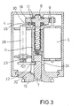
- the securing lever 22 which is required in order to fix the blocking element 7 is mechanically pivoted out of the recess 24 in the blocking element 7 by means of a shaft 28.
- the shaft 28 is activated by the thread spindle and, for this purpose, has, on its side which is remote from the securing lever 22, a control projection 29 which is supported on a control cam 30 driven by the threaded spindle 8.
- the invention is not limited to the exemplary embodiments described above.
- the securing lever may also engage in a suitable recess in the driver in order for the blocking element to be fixed in its unlocked position.
- limit stops of the driver may be replaced by limit stops for the blocking element, in which case the limit stop in the locked position of the blocking element is defined, for example, by the blocking element coming into contact with the steering shaft.
- the blocking element may also, for example, comprise two blocking pins which are arranged one behind the other in the direction of the longitudinal axis of the steering shaft.
- Fig. 4 and 5 show a corresponding exemplary embodiment. These figures show an arrangement substantially as illustrated in Fig. 2. The parts corresponding to Fig. 2 are therefore provided with the same reference numerals in Fig. 4.
- the reference numeral 31 denotes a steering shaft on which a toothed ring 32 is arranged which, as seen in the direction of the longitudinal axis 33 of the steering shaft, has two toothed ring areas 34, 35 which, as seen in the circumferential direction, are offset with respect to one another.
- the locking element 36 of the arrangement according to the invention comprises two spring-loaded blocking pins 37, 38 which are arranged one behind the other and, in their locked position, each engage in an associated toothed ring area 34, 35.
- the driver 11 is of U-shaped design at its bottom end (Fig. 5), the two limbs 39, 40 each having a holding strip 41, 42 in such a manner that the blocking pins 37, 38 engage around the top side of the holding strips 41, 42 of the driver.
- This design of the seat ensures that both blocking pins 37, 38 of the blocking element 36 are held securely in the seat.
- the blocking pins 37, 38 of the blocking element 36 are mounted resiliently in the axial direction in the seat of the driver 11, by way of two compression springs 43, 44.
Abstract
Description
- The invention relates to an arrangement for electrically locking the steering shaft of a steering device of a motor vehicle.
- An arrangement of this nature is known, for example, from DE 197 19 343 C1. This known arrangement comprises an electric motor which is arranged in a housing and has an actuator connected downstream for displacing a blocking element from its locked position into its unlocked position and vice versa, the blocking element, in its locked position, engaging in the recess, formed by adjacent teeth, in a toothed ring which is attached to the steering shaft and thus blocking the steering shaft. In the known arrangement, a cam drive is used as the actuator for displacing the blocking element.
- A drawback of this known arrangement is that the use of the cam drive involves relatively long locking and unlocking times.
- DE 37 39 172 C1 has also disclosed an arrangement for displacing a blocking element, in which an electric motor (not shown in detail) drives a worm wheel which engages in the teeth of the blocking element, which is partly designed as a rack.
- One of the drawbacks of this arrangement is that a relatively powerful electric motor is required for the necessary displacement of the blocking element, and this requires a correspondingly large structural space.
- The invention is based on the object of providing an arrangement of the type described in the introduction with which, on the one hand, it is possible to achieve short unlocking times for the blocking element and which, on the other hand, is of very space-saving design.
- According to the invention, this object is achieved by means of the features of claim 1. Further, particularly advantageous configurations of the invention are disclosed in the subclaims.
- The invention is fundamentally based on the principle of using a spindle drive as the actuator, with a driver with internal screw thread arranged on the threaded spindle, which driver can be displaced in linear fashion, engages in the screw thread of the threaded spindle and, on its side which is remote from the threaded spindle, has a seat for the blocking element. Moreover, to guide the blocking element, the arrangement comprises an adapter part which is connected to the housing and can likewise be connected to the steering device. The adapter part is designed in such a manner that, in the event of the steering shaft being twisted violently in the locked position of the blocking element, it absorbs the forces acting on this element, thus reliably preventing damage to the spindle drive and the electric motor.
- In order to move the locking mechanism into defined limit positions, limit stops for the driver or the blocking element are provided. For this purpose, the drive provided by the electric motor is activated for a longer time than is required for the unlocking or locking operation. After this time, the electric motor is switched off by means of an electronic switching arrangement, so that - in contrast to known arrangements - there is no need for limit-position sensors.
- To avoid excessive loads being imposed on components when the driver reaches the limit positions, the threaded spindle is advantageously supported against the housing of the arrangement according to the invention elastically in the axial direction by means of springs, preferably cup springs. When the movement of the driver is blocked in the limit positions, the threaded spindle can rotate still further, thus compressing the cup springs. As a result, the excess force generated by the mass moments of inertia of the mechanism is reduced and it is possible to dispense with space-consuming slipping clutches or long threaded spindles with a torsion bar action.
- In a further advantageous embodiment of the invention, the blocking element is provided with a lateral recess, into which a securing lever can be pivoted by means of a preloaded spring in order for the blocking element to be fixed in the unlocked position. For the blocking element to be displaced from the unlocked position into the locked position, the securing lever is firstly pivoted out of the recess by means of a second electric motor or by means of a shaft which is activated by the threaded spindle.
- Preferably, the adapter part is arranged exchangeably on the housing and the blocking element is arranged on the seat of the driver, so that the arrangement according to the invention can easily be adapted to the steering devices of different vehicle manufacturers simply by changing these parts.
- It has proven advantageous if the blocking element, as seen in the direction of the longitudinal axis of the steering shaft, comprises two spring-loaded blocking pins which are arranged one behind the other. This is because if a blocking element with only one blocking pin is used, this pin, when it is being displaced into the locked position, often strikes a tooth of the toothed ring arranged on the steering shaft, so that the steering shaft has to be rotated further in order for it to be locked, whereas using two blocking pins ensures that one of the two blocking pins always engages in the recesses in a toothed ring which are defined by adjacent teeth. If the blocking bolts are arranged one behind the other in the axial direction of the steering shaft, however, each blocking bolt must be assigned its own toothed ring (or toothed ring area), in which case the two toothed rings (or toothed ring areas) are then offset with respect to one another on the steering shaft.
- Further details and advantages of the invention will emerge from the following exemplary embodiments explained with reference to figures, in which:
- Fig. 1
- shows a longitudinal section through an arrangement according to the invention with a blocking element which can be displaced by means of a spindle drive and is in its unlocked position;
- Fig. 2
- shows a view corresponding to Fig. 1, with the blocking element fixed in its unlocked position by a spring-loaded, pivotable securing lever which can be pivoted by means of an electric motor;
- Fig. 3
- shows a view corresponding to Fig. 2, in which the spring-loaded securing lever can be pivoted by means of a shaft which is connected to the drive of the blocking element;
- Fig. 4
- shows a perspective view of a further exemplary embodiment of the invention, in which the blocking element comprises two blocking pins which are arranged one behind the other;
- Fig. 5
- shows a side view of the connecting area between the spindle drive and the blocking element used in Fig. 4.
- In Fig. 1, 1 denotes an arrangement according to the invention for electrically locking a steering shaft, denoted by 2, of a motor vehicle, having a
toothed ring 3. - The arrangement 1 comprises a
housing 4 and a firstelectric motor 5 which is arranged in the housing and has aspindle drive 6 connected downstream. This drive displaces a spring-loadedblocking element 7 from the unlocked position shown in Fig. 1 into a locked position (not shown) in which theblocking element 7 engages in the recess formed by adjacent teeth of thetoothed ring 3. - The
spindle drive 6 comprises a threadedspindle 8, which is driven by means of atoothed transmission 9 of the firstelectric motor 5, and adriver 11, which is mounted in a guide and has an internal screw thread 12 which engages in the screw thread 13 of the threadedspindle 8. On its side facing toward theblocking element 7, thedriver 11 has aseat 14, via which theblocking element 7, on its side which is remote from thesteering shaft 2, is connected to thedriver 11. - Moreover, to guide the blocking
element 7, the arrangement 1 according to the invention comprises anadapter part 15, which can be connected to thehousing 4 and the steering device of the vehicle and by means of which the arrangement 1 is attached to the steering device. Theadapter part 15 is designed in such a manner that, in the event thesteering shaft 2 being twisted violently in the locked position of the blockingelement 7, it absorbs the forces acting on the latter. Theadapter part 15 is attached to the steering device by means of ascrew 16, for example (cf. also Fig. 4). - On its side which is remote from the
driver 11, the threadedspindle 8 is supported against thehousing 4 elastically in the axial direction by means ofcup springs 17, which are arranged on either side of agearwheel 18, attached to the threadedspindle 8, of thetoothed transmission 9, in such a manner that the threadedspindle 8 rotates still further counter to the pressure of the cup springs 17 (and correspondingly moves in the axial direction) when thedriver 11 has already reached its limit position and is blocked by acorresponding limit stop - The arrangement 1 is furthermore connected to an
electronic switching arrangement 21 which generates the control signals for the firstelectric motor 5 and is designed in such a manner that, after theelectric motor 5 has been activated, the motor is switched off automatically after a predeterminable time, this time being selected to be longer than would be necessary for the unlocking or locking operation. - Fig. 2 again shows the arrangement 1 illustrated in Fig. 1, but in this case, in order for the blocking
element 7 to be additionally fixed in the unlocked position, asecuring lever 22 is provided, which is arranged so that it can be pivoted into arecess 24 in the blockingelement 7 through arecess 10 in theadapter part 15 by means of a preloadedtorsion spring 23. In order for it subsequently to be possible for the blockingelement 7 to be displaced out of the unlocked position into the locked position, firstly thesecuring lever 22 is pivoted back out of therecess 24 by means of a secondelectric motor 25, and then it is displaced with the aid of the spindle drive 6 (Fig. 1), in which case the second electric motor can also be activated by means of theelectronic switching arrangement 21 illustrated in Fig. 1. - In order for it to be possible to detect the position of the
securing lever 22, a magnet 26 is arranged on the latter and a magnetic field sensor 27 (e.g. a Hall sensor) is arranged in its vicinity inside thehousing 4, which sensor responds as soon as the blockingelement 7 is in its unlocked position. - In the exemplary embodiment illustrated in Fig. 3, the
securing lever 22 which is required in order to fix the blockingelement 7 is mechanically pivoted out of therecess 24 in the blockingelement 7 by means of ashaft 28. Theshaft 28 is activated by the thread spindle and, for this purpose, has, on its side which is remote from thesecuring lever 22, a control projection 29 which is supported on acontrol cam 30 driven by the threadedspindle 8. - Naturally, the invention is not limited to the exemplary embodiments described above. For example, the securing lever may also engage in a suitable recess in the driver in order for the blocking element to be fixed in its unlocked position.
- Furthermore, the limit stops of the driver may be replaced by limit stops for the blocking element, in which case the limit stop in the locked position of the blocking element is defined, for example, by the blocking element coming into contact with the steering shaft.
- The blocking element may also, for example, comprise two blocking pins which are arranged one behind the other in the direction of the longitudinal axis of the steering shaft. Fig. 4 and 5 show a corresponding exemplary embodiment. These figures show an arrangement substantially as illustrated in Fig. 2. The parts corresponding to Fig. 2 are therefore provided with the same reference numerals in Fig. 4.
- In Fig. 4, the
reference numeral 31 denotes a steering shaft on which atoothed ring 32 is arranged which, as seen in the direction of thelongitudinal axis 33 of the steering shaft, has twotoothed ring areas - The
locking element 36 of the arrangement according to the invention comprises two spring-loadedblocking pins toothed ring area - To connect to the
blocking element 36, thedriver 11 is of U-shaped design at its bottom end (Fig. 5), the twolimbs holding strip pins holding strips pins element 36 are held securely in the seat. Theblocking pins element 36 are mounted resiliently in the axial direction in the seat of thedriver 11, by way of twocompression springs 43, 44. -
- 1
- Arrangement
- 2
- Steering shaft
- 3
- Toothed ring
- 4
- Housing
- 5
- First electric motor
- 6
- Spindle drive, actuator
- 7
- Blocking element
- 8
- Threaded spindle
- 9
- Toothed transmission
- 10
- Recess (adapter part)
- 11
- Driver
- 12
- Internal screw thread
- 13
- Screw thread (threaded spindle)
- 14
- Seat
- 15
- Adapter part
- 16
- Screw
- 17
- Cup springs
- 18
- Gear wheel
- 19, 20
- Limit stops
- 21
- Electronic switching arrangement
- 22
- Securing lever
- 23
- Torsion spring, spring
- 24
- Recess
- 25
- Second electric motor; device
- 26
- Magnet
- 27
- Sensor, magnetic field sensor, Hall sensor
- 28
- Shaft, device
- 29
- Control projection
- 30
- Control cam
- 31
- Steering shaft
- 32
- Toothed ring
- 33
- Longitudinal axis
- 34, 35
- Toothed ring areas
- 36
- Blocking element
- 37, 38
- Blocking pins
- 39, 40
- Limbs
- 41, 42
- Holding bars
- 43, 44
- Springs
Claims (12)
- An arrangement for electrically locking the steering shaft (2; 31) of a steering device of a motor vehicle, having the following features:a) the arrangement (1) comprises a housing (4) and a first electric motor (5), which is arranged in the housing and has an actuator (6) connected downstream for displacing a blocking element (7; 36) which is arranged so that it can be displaced from its unlocked position into a locked position;b) the actuator (6) is a spindle drive having a threaded spindle (8), which is connected via a toothed transmission (9), and a driver (11), which can be displaced in linear fashion in a guide and has an internal screw thread 12 which engages in the screw thread (13) of the threaded spindle (8);c) on its side facing toward the blocking element (7; 36), the driver (11) has a seat (14), via which the blocking element (7;36), on its side which is remote from the steering shaft (2; 31), can be connected to the driver (11), andd) to guide the blocking element (7; 36), the arrangement (1) comprises an adapter part (15) which can be connected to the steering device of the vehicle and is designed in such a manner that if the steering shaft (2; 31) is twisted violently in the locked position of the blocking element (7; 36), it absorbs the forces acting on this part.
- The arrangement as claimed in claim 1, wherein the threaded spindle (8) is supported against the housing (4) elastically in the axial direction by means of springs (17), so that the threaded spindle (8), when the driver (11) has already reached its limit position and is blocked by a limit stop (19; 20), can rotate still further counter to the pressure of one of the springs (17).
- The arrangement as claimed in claim 2, wherein the threaded spindle (8), on its side which is remote from the driver (11), is supported against the housing (4) elastically, in the axial direction, by means of cup springs (17) which are arranged on either side of a gearwheel (18) which is attached to the threaded spindle (8).
- The arrangement as claimed in one of claims 1 to 3, which is connected to an electronic switching arrangement (21) which generates the control signals for the first electric motor (5) and is designed in such a manner that, after the electric motor (5) has been activated, the motor is automatically switched off after a predeterminable time, this time being selected to be longer than would be required for the unlocking or locking operation.
- The arrangement as claimed in one of claims 1 to 4, wherein
the blocking element (7; 36) or the driver (11) includes a lateral recess (24),
wherein the arrangement (1) comprises a pivotable securing lever (22), which is arranged in the housing (4) and is preloaded by a spring (23), in such a manner that the spring (23), in the unlocked position of the blocking element (7; 36), pivots the securing lever (22) into the recess (24) and fixes the blocking element (7; 36) in this position, and
wherein a device (25; 28) is provided, by means of which the securing lever (22) can be pivoted out of the recess (24) counter to the pressure of the spring (23), before the blocking element (7; 36) is displaced into its locked position. - The arrangement as claimed in claim 5, wherein the device (25) for pivoting the securing lever (22) out of the recess (24) in the blocking element (7; 36) is a second electric motor, which is likewise activated by the electronic switching arrangement (21).
- The arrangement as claimed in claim 5, wherein the device (28) for pivoting the securing lever (22) out of the recess (24) in the blocking element (7; 36) is a shaft (28) which is connected to the securing lever (22), extends in the axial direction of the threaded spindle (8) and, on its side which is remote from the securing lever (22), bears a control projection (29) which is supported on a control cam (30) which is driven by the threaded spindle (8).
- The arrangement as claimed in one of claims 5 to 7, wherein the securing lever (22) is arranged to the side of the adapter part (15), and wherein a slot-like recess (10) is provided in the side wall of the adapter part (15), through which recess the securing lever (22) can be pivoted, so that it engages in the recess (24) in the blocking element (7; 36) in the unlocked position of the blocking element (7; 36).
- The arrangement as claimed in one of claims 5 to 8, wherein at least one sensor (27) is arranged in the housing (4) of the arrangement (1), in order to monitor the position of the securing lever (22).
- The arrangement as claimed in claim 9, wherein the sensor (27) is a Hall sensor.
- The arrangement as claimed in one of claims 1 to 10, wherein the adapter part (15) is arranged exchangeably on the housing (4) of the arrangement (1).
- The arrangement as claimed in one of claims 1 to 11, wherein the blocking element (36), as seen in the direction of the longitudinal axis (33) of the steering shaft (31) comprises two spring-loaded blocking pins (37, 38) which are arranged one behind the other.
Applications Claiming Priority (2)
| Application Number | Priority Date | Filing Date | Title |
|---|---|---|---|
| DE19906268 | 1999-02-15 | ||
| DE1999106268 DE19906268C2 (en) | 1999-02-15 | 1999-02-15 | Device for electrically locking the steering spindle of a steering device |
Publications (3)
| Publication Number | Publication Date |
|---|---|
| EP1029755A2 true EP1029755A2 (en) | 2000-08-23 |
| EP1029755A3 EP1029755A3 (en) | 2001-01-17 |
| EP1029755B1 EP1029755B1 (en) | 2005-05-18 |
Family
ID=7897552
Family Applications (1)
| Application Number | Title | Priority Date | Filing Date |
|---|---|---|---|
| EP20000400325 Expired - Lifetime EP1029755B1 (en) | 1999-02-15 | 2000-02-04 | Arrangement for electrically locking the steering shaft of a steering device |
Country Status (4)
| Country | Link |
|---|---|
| EP (1) | EP1029755B1 (en) |
| JP (1) | JP4606538B2 (en) |
| DE (1) | DE19964173C2 (en) |
| ES (1) | ES2242584T3 (en) |
Cited By (16)
| Publication number | Priority date | Publication date | Assignee | Title |
|---|---|---|---|---|
| DE10109989A1 (en) * | 2001-03-01 | 2002-09-05 | Conti Temic Microelectronic | Steering wheel lock for motor vehicles |
| DE10136221A1 (en) * | 2001-07-25 | 2003-02-20 | Conti Temic Microelectronic | locking device |
| EP1621423A1 (en) * | 2004-07-29 | 2006-02-01 | Kabushiki Kaisha Tokai Rika Denki Seisakusho | Steering lock |
| EP1637415A1 (en) | 2004-09-15 | 2006-03-22 | Valeo Sicherheitssysteme GmbH | Electrical device for locking/unlocking a steering column |
| WO2007127962A2 (en) * | 2006-04-27 | 2007-11-08 | Stoneridge Control Devices, Inc. | Steering shaft lock actuator |
| EP1982878A3 (en) * | 2007-04-16 | 2009-07-01 | Huf Hülsbeck & Fürst GmbH & Co. KG | Device for operating a blocking element |
| DE102008016820A1 (en) * | 2008-04-01 | 2009-10-08 | Huf Hülsbeck & Fürst Gmbh & Co. Kg | Device for controlling a blocking unit |
| KR100954065B1 (en) | 2008-03-21 | 2010-04-20 | 대성전기공업 주식회사 | Electronic steering column locking apparatus |
| EP2476593A1 (en) | 2011-01-13 | 2012-07-18 | Valeo Sicherheitssysteme GmbH | Theft protection method for an automobile |
| WO2012095453A1 (en) | 2011-01-13 | 2012-07-19 | Valeo Sicherheitssysteme Gmbh | Method for automatically controlling the electric steering lock for the steering column of a motor vehicle |
| CN102019907B (en) * | 2009-09-16 | 2012-12-12 | 比亚迪股份有限公司 | Steering shaft lock |
| EP2653356A4 (en) * | 2010-12-17 | 2014-07-30 | Honda Lock Kk | Vehicular electric lock device |
| EP3162642A1 (en) * | 2015-10-27 | 2017-05-03 | Asahi Denso Co., Ltd. | Steering lock device |
| CN108791185A (en) * | 2018-06-29 | 2018-11-13 | 昌辉汽车电器(黄山)股份公司 | A kind of flat motion structure of electronics tubing string water lock |
| WO2021069405A1 (en) * | 2019-10-11 | 2021-04-15 | Thyssenkrupp Presta Ag | Locking device and steering column with locking device |
| WO2022109645A1 (en) * | 2020-11-26 | 2022-06-02 | STIWA Advanced Products GmbH | Locking device |
Families Citing this family (12)
| Publication number | Priority date | Publication date | Assignee | Title |
|---|---|---|---|---|
| JP2002234419A (en) * | 2001-02-09 | 2002-08-20 | Tokai Rika Co Ltd | Electronic steering lock mechanism |
| DE10109609C1 (en) * | 2001-02-28 | 2002-10-10 | Huf Huelsbeck & Fuerst Gmbh | Lock, in particular for locking the steering spindle of a motor vehicle |
| JP4502539B2 (en) * | 2001-03-28 | 2010-07-14 | 株式会社ホンダロック | Vehicle steering lock device |
| JP4502538B2 (en) * | 2001-03-28 | 2010-07-14 | 株式会社ホンダロック | Vehicle steering lock device |
| DE102004053438A1 (en) | 2004-11-05 | 2006-05-11 | Valeo Sicherheitssysteme Gmbh | steering lock |
| DE102005027777A1 (en) * | 2005-06-15 | 2006-12-21 | Huf Hülsbeck & Fürst Gmbh & Co. Kg | Locking device for a steering shaft with selectable switch-off position upon movement of the locking pin assembly in the direction of a release end position |
| DE102005050920B4 (en) * | 2005-10-21 | 2017-11-30 | Huf Hülsbeck & Fürst GmbH & Co KG | locking device |
| JP2007153172A (en) * | 2005-12-06 | 2007-06-21 | Tokai Rika Co Ltd | Electric steering lock device |
| DE102007059710B4 (en) | 2007-12-10 | 2021-01-21 | Huf Hülsbeck & Fürst Gmbh & Co. Kg | Compact locking device with safety element |
| JP5175698B2 (en) * | 2008-11-27 | 2013-04-03 | 株式会社アルファ | Steering lock device |
| JP4815515B2 (en) * | 2009-07-22 | 2011-11-16 | 株式会社ホンダロック | Vehicle steering lock device |
| JP6325207B2 (en) * | 2013-07-01 | 2018-05-16 | 株式会社ユーシン | Electric steering lock device |
Citations (3)
| Publication number | Priority date | Publication date | Assignee | Title |
|---|---|---|---|---|
| DE3739172C1 (en) * | 1987-11-19 | 1989-02-09 | Daimler Benz Ag | Locking system for motor vehicles |
| DE4422467C1 (en) * | 1994-06-28 | 1995-06-08 | Kostal Leopold Gmbh & Co Kg | Anti-theft steering lock for vehicle |
| EP0844154A2 (en) * | 1996-11-13 | 1998-05-27 | Kabushiki Kaisha Tokai Rika Denki Seisakusho | Steering lock system |
Family Cites Families (3)
| Publication number | Priority date | Publication date | Assignee | Title |
|---|---|---|---|---|
| JP2501752Y2 (en) * | 1990-04-21 | 1996-06-19 | 日本精工株式会社 | Steering lock device |
| JP2537511Y2 (en) * | 1991-03-15 | 1997-06-04 | 株式会社東海理化電機製作所 | Steering lock device |
| FR2766441B1 (en) * | 1997-07-24 | 1999-09-10 | Valeo Securite Habitacle | ELECTRICAL THEFT COMPRISING ADDITIONAL MEANS FOR LOCKING THE PENEER |
-
1999
- 1999-02-15 DE DE19964173A patent/DE19964173C2/en not_active Expired - Fee Related
-
2000
- 2000-02-04 ES ES00400325T patent/ES2242584T3/en not_active Expired - Lifetime
- 2000-02-04 EP EP20000400325 patent/EP1029755B1/en not_active Expired - Lifetime
- 2000-02-15 JP JP2000036409A patent/JP4606538B2/en not_active Expired - Fee Related
Patent Citations (3)
| Publication number | Priority date | Publication date | Assignee | Title |
|---|---|---|---|---|
| DE3739172C1 (en) * | 1987-11-19 | 1989-02-09 | Daimler Benz Ag | Locking system for motor vehicles |
| DE4422467C1 (en) * | 1994-06-28 | 1995-06-08 | Kostal Leopold Gmbh & Co Kg | Anti-theft steering lock for vehicle |
| EP0844154A2 (en) * | 1996-11-13 | 1998-05-27 | Kabushiki Kaisha Tokai Rika Denki Seisakusho | Steering lock system |
Cited By (31)
| Publication number | Priority date | Publication date | Assignee | Title |
|---|---|---|---|---|
| DE10109989B4 (en) * | 2001-03-01 | 2010-04-15 | Fendt, Günter | Steering wheel lock for motor vehicles |
| DE10109989A1 (en) * | 2001-03-01 | 2002-09-05 | Conti Temic Microelectronic | Steering wheel lock for motor vehicles |
| DE10136221A1 (en) * | 2001-07-25 | 2003-02-20 | Conti Temic Microelectronic | locking device |
| DE10136221C2 (en) * | 2001-07-25 | 2003-07-17 | Conti Temic Microelectronic | locking device |
| EP1621423A1 (en) * | 2004-07-29 | 2006-02-01 | Kabushiki Kaisha Tokai Rika Denki Seisakusho | Steering lock |
| US7086256B2 (en) | 2004-07-29 | 2006-08-08 | Kabushiki Kaisha Tokai Rika Denki Seisakusho | Steering lock |
| CN100423974C (en) * | 2004-07-29 | 2008-10-08 | 株式会社东海理化电机制作所 | Steering lock |
| EP1637415A1 (en) | 2004-09-15 | 2006-03-22 | Valeo Sicherheitssysteme GmbH | Electrical device for locking/unlocking a steering column |
| EP1637415B2 (en) † | 2004-09-15 | 2019-01-09 | U-Shin Deutschland Zugangssysteme GmbH | Electrical device for locking/unlocking a steering column |
| EP1637415B1 (en) | 2004-09-15 | 2015-11-04 | U-Shin Deutschland Zugangssysteme GmbH | Electrical device for locking/unlocking a steering column |
| GB2450301B (en) * | 2006-04-27 | 2011-07-27 | Stoneridge Control Devices Inc | Steering shaft lock actuator |
| GB2450301A (en) * | 2006-04-27 | 2008-12-17 | Stoneridge Control Devices Inc | Steering shaft lock actuator |
| US8006526B2 (en) | 2006-04-27 | 2011-08-30 | Stoneridge Control Devices, Inc. | Steering shaft lock actuator |
| WO2007127962A2 (en) * | 2006-04-27 | 2007-11-08 | Stoneridge Control Devices, Inc. | Steering shaft lock actuator |
| WO2007127962A3 (en) * | 2006-04-27 | 2008-10-30 | Stoneridge Control Devices Inc | Steering shaft lock actuator |
| EP1982878A3 (en) * | 2007-04-16 | 2009-07-01 | Huf Hülsbeck & Fürst GmbH & Co. KG | Device for operating a blocking element |
| KR100954065B1 (en) | 2008-03-21 | 2010-04-20 | 대성전기공업 주식회사 | Electronic steering column locking apparatus |
| DE102008016820A1 (en) * | 2008-04-01 | 2009-10-08 | Huf Hülsbeck & Fürst Gmbh & Co. Kg | Device for controlling a blocking unit |
| CN102019907B (en) * | 2009-09-16 | 2012-12-12 | 比亚迪股份有限公司 | Steering shaft lock |
| EP2653356A4 (en) * | 2010-12-17 | 2014-07-30 | Honda Lock Kk | Vehicular electric lock device |
| US9422753B2 (en) | 2010-12-17 | 2016-08-23 | Kabushiki Kaisha Honda Lock | Vehicular electric lock device |
| EP2476593A1 (en) | 2011-01-13 | 2012-07-18 | Valeo Sicherheitssysteme GmbH | Theft protection method for an automobile |
| JP2014505626A (en) * | 2011-01-13 | 2014-03-06 | ヴァレオ ジヒャーハイツズュステーメ ゲーエムベーハー | Method for automatically controlling an electric steering column locking device of an automobile |
| WO2012095452A1 (en) | 2011-01-13 | 2012-07-19 | Valeo Sicherheitssysteme Gmbh | Method for protecting against the theft of a motor vehicle |
| WO2012095453A1 (en) | 2011-01-13 | 2012-07-19 | Valeo Sicherheitssysteme Gmbh | Method for automatically controlling the electric steering lock for the steering column of a motor vehicle |
| EP3162642A1 (en) * | 2015-10-27 | 2017-05-03 | Asahi Denso Co., Ltd. | Steering lock device |
| US9889817B2 (en) | 2015-10-27 | 2018-02-13 | Asahi Denso Co., Ltd. | Steering lock device |
| CN108791185A (en) * | 2018-06-29 | 2018-11-13 | 昌辉汽车电器(黄山)股份公司 | A kind of flat motion structure of electronics tubing string water lock |
| CN108791185B (en) * | 2018-06-29 | 2024-04-09 | 昌辉汽车电器(黄山)股份公司 | Horizontal movement structure of electronic tubular column lock |
| WO2021069405A1 (en) * | 2019-10-11 | 2021-04-15 | Thyssenkrupp Presta Ag | Locking device and steering column with locking device |
| WO2022109645A1 (en) * | 2020-11-26 | 2022-06-02 | STIWA Advanced Products GmbH | Locking device |
Also Published As
| Publication number | Publication date |
|---|---|
| JP2000233717A (en) | 2000-08-29 |
| DE19964173C2 (en) | 2001-12-13 |
| EP1029755A3 (en) | 2001-01-17 |
| ES2242584T3 (en) | 2005-11-16 |
| EP1029755B1 (en) | 2005-05-18 |
| JP4606538B2 (en) | 2011-01-05 |
Similar Documents
| Publication | Publication Date | Title |
|---|---|---|
| EP1029755B1 (en) | Arrangement for electrically locking the steering shaft of a steering device | |
| EP3261875B1 (en) | Actuator and method of actuating a latch | |
| JP4698019B2 (en) | Locking device | |
| US20020108412A1 (en) | Locking device | |
| CN104847190B (en) | Actuator for vehicle lock bolt and the vehicle lock bolt with actuator | |
| JP5745645B2 (en) | Front and rear adjustment device for automobile seats with two rail pairs | |
| US6125671A (en) | Steering lock system | |
| JP4448512B2 (en) | Device for locking the steering shaft of an automobile | |
| KR101165279B1 (en) | Eccentric gearing | |
| EP3400351B1 (en) | Electromechanical door lock actuation device | |
| US20120260701A1 (en) | Steering locking device | |
| KR101378620B1 (en) | Electrically lockable vehicle steering system | |
| CN111356849B (en) | Electric drive for motor vehicle applications | |
| KR20120007531A (en) | Locking apparatus for a vehicle seat | |
| CN111727531B (en) | Locking device for charging device | |
| US20060278029A1 (en) | Driving gear selector device for an automatic transmission of a motor vehicle | |
| CN101827733B (en) | Device for activating a blocking element | |
| CN108468800B (en) | Actuator with release and return mechanism | |
| JP2010142642A (en) | Locking device for vehicle seat | |
| CN112739936A (en) | Electromechanical parking brake | |
| US11193586B2 (en) | Parking lock and a transmission having the parking lock | |
| US20190016300A1 (en) | Steering column with an electrical steering lock | |
| WO2010020665A1 (en) | Drive device for entrance/exit devices with coupling | |
| CN111356606B (en) | Electrical connection device for an electric or hybrid vehicle | |
| CN111565967A (en) | Locking device for an electrical connection device of an electric or hybrid vehicle |
Legal Events
| Date | Code | Title | Description |
|---|---|---|---|
| PUAI | Public reference made under article 153(3) epc to a published international application that has entered the european phase |
Free format text: ORIGINAL CODE: 0009012 |
|
| AK | Designated contracting states |
Kind code of ref document: A2 Designated state(s): ES FR GB IT |
|
| AX | Request for extension of the european patent |
Free format text: AL;LT;LV;MK;RO;SI |
|
| PUAL | Search report despatched |
Free format text: ORIGINAL CODE: 0009013 |
|
| AK | Designated contracting states |
Kind code of ref document: A3 Designated state(s): AT BE CH CY DE DK ES FI FR GB GR IE IT LI LU MC NL PT SE |
|
| AX | Request for extension of the european patent |
Free format text: AL;LT;LV;MK;RO;SI |
|
| 17P | Request for examination filed |
Effective date: 20010717 |
|
| AKX | Designation fees paid |
Free format text: ES FR GB IT |
|
| REG | Reference to a national code |
Ref country code: DE Ref legal event code: 8566 |
|
| GRAH | Despatch of communication of intention to grant a patent |
Free format text: ORIGINAL CODE: EPIDOS IGRA |
|
| GRAS | Grant fee paid |
Free format text: ORIGINAL CODE: EPIDOSNIGR3 |
|
| RAP1 | Party data changed (applicant data changed or rights of an application transferred) |
Owner name: VALEO DEUTSCHLAND GMBH & CO.SICHERHEITSSYSTEME |
|
| RAP1 | Party data changed (applicant data changed or rights of an application transferred) |
Owner name: VALEO DEUTSCHLAND GMBH & CO.SICHERHEITSSYSTEME |
|
| RAP1 | Party data changed (applicant data changed or rights of an application transferred) |
Owner name: VALEO SICHERHEITSSYSTEME GMBH |
|
| GRAJ | Information related to disapproval of communication of intention to grant by the applicant or resumption of examination proceedings by the epo deleted |
Free format text: ORIGINAL CODE: EPIDOSDIGR1 |
|
| GRAL | Information related to payment of fee for publishing/printing deleted |
Free format text: ORIGINAL CODE: EPIDOSDIGR3 |
|
| 17Q | First examination report despatched |
Effective date: 20040505 |
|
| GRAP | Despatch of communication of intention to grant a patent |
Free format text: ORIGINAL CODE: EPIDOSNIGR1 |
|
| GRAS | Grant fee paid |
Free format text: ORIGINAL CODE: EPIDOSNIGR3 |
|
| GRAA | (expected) grant |
Free format text: ORIGINAL CODE: 0009210 |
|
| AK | Designated contracting states |
Kind code of ref document: B1 Designated state(s): ES FR GB IT |
|
| REG | Reference to a national code |
Ref country code: GB Ref legal event code: FG4D |
|
| REG | Reference to a national code |
Ref country code: ES Ref legal event code: FG2A Ref document number: 2242584 Country of ref document: ES Kind code of ref document: T3 |
|
| ET | Fr: translation filed | ||
| PLBE | No opposition filed within time limit |
Free format text: ORIGINAL CODE: 0009261 |
|
| STAA | Information on the status of an ep patent application or granted ep patent |
Free format text: STATUS: NO OPPOSITION FILED WITHIN TIME LIMIT |
|
| 26N | No opposition filed |
Effective date: 20060221 |
|
| REG | Reference to a national code |
Ref country code: ES Ref legal event code: PC2A Owner name: U-SHIN DEUTSCHLAND ZUGANGSSYSTEME GMBH Effective date: 20150618 |
|
| REG | Reference to a national code |
Ref country code: FR Ref legal event code: PLFP Year of fee payment: 17 |
|
| REG | Reference to a national code |
Ref country code: FR Ref legal event code: PLFP Year of fee payment: 18 |
|
| PGFP | Annual fee paid to national office [announced via postgrant information from national office to epo] |
Ref country code: FR Payment date: 20170228 Year of fee payment: 18 |
|
| PGFP | Annual fee paid to national office [announced via postgrant information from national office to epo] |
Ref country code: GB Payment date: 20170214 Year of fee payment: 18 |
|
| PGFP | Annual fee paid to national office [announced via postgrant information from national office to epo] |
Ref country code: IT Payment date: 20170217 Year of fee payment: 18 Ref country code: ES Payment date: 20170228 Year of fee payment: 18 |
|
| GBPC | Gb: european patent ceased through non-payment of renewal fee |
Effective date: 20180204 |
|
| REG | Reference to a national code |
Ref country code: FR Ref legal event code: ST Effective date: 20181031 |
|
| PG25 | Lapsed in a contracting state [announced via postgrant information from national office to epo] |
Ref country code: FR Free format text: LAPSE BECAUSE OF NON-PAYMENT OF DUE FEES Effective date: 20180228 Ref country code: GB Free format text: LAPSE BECAUSE OF NON-PAYMENT OF DUE FEES Effective date: 20180204 Ref country code: IT Free format text: LAPSE BECAUSE OF NON-PAYMENT OF DUE FEES Effective date: 20180204 |
|
| REG | Reference to a national code |
Ref country code: ES Ref legal event code: FD2A Effective date: 20190801 |
|
| PG25 | Lapsed in a contracting state [announced via postgrant information from national office to epo] |
Ref country code: ES Free format text: LAPSE BECAUSE OF NON-PAYMENT OF DUE FEES Effective date: 20180205 |