EP1029594A2 - Honeycomb structural body - Google Patents
Honeycomb structural body Download PDFInfo
- Publication number
- EP1029594A2 EP1029594A2 EP00301128A EP00301128A EP1029594A2 EP 1029594 A2 EP1029594 A2 EP 1029594A2 EP 00301128 A EP00301128 A EP 00301128A EP 00301128 A EP00301128 A EP 00301128A EP 1029594 A2 EP1029594 A2 EP 1029594A2
- Authority
- EP
- European Patent Office
- Prior art keywords
- honeycomb structural
- structural body
- main material
- portions
- wall portion
- Prior art date
- Legal status (The legal status is an assumption and is not a legal conclusion. Google has not performed a legal analysis and makes no representation as to the accuracy of the status listed.)
- Granted
Links
- 239000000463 material Substances 0.000 claims abstract description 119
- 238000005192 partition Methods 0.000 claims 3
- 238000004901 spalling Methods 0.000 abstract description 17
- 239000000203 mixture Substances 0.000 description 16
- 229910001233 yttria-stabilized zirconia Inorganic materials 0.000 description 11
- PNEYBMLMFCGWSK-UHFFFAOYSA-N aluminium oxide Inorganic materials [O-2].[O-2].[O-2].[Al+3].[Al+3] PNEYBMLMFCGWSK-UHFFFAOYSA-N 0.000 description 10
- 238000001125 extrusion Methods 0.000 description 10
- XLYOFNOQVPJJNP-UHFFFAOYSA-N water Substances O XLYOFNOQVPJJNP-UHFFFAOYSA-N 0.000 description 10
- NFYLSJDPENHSBT-UHFFFAOYSA-N chromium(3+);lanthanum(3+);oxygen(2-) Chemical compound [O-2].[O-2].[O-2].[Cr+3].[La+3] NFYLSJDPENHSBT-UHFFFAOYSA-N 0.000 description 9
- 239000003054 catalyst Substances 0.000 description 7
- 239000002245 particle Substances 0.000 description 7
- 238000000034 method Methods 0.000 description 6
- 239000000843 powder Substances 0.000 description 6
- 239000004372 Polyvinyl alcohol Substances 0.000 description 5
- 230000000052 comparative effect Effects 0.000 description 5
- 238000004898 kneading Methods 0.000 description 5
- 229920002451 polyvinyl alcohol Polymers 0.000 description 5
- 229910052878 cordierite Inorganic materials 0.000 description 4
- JSKIRARMQDRGJZ-UHFFFAOYSA-N dimagnesium dioxido-bis[(1-oxido-3-oxo-2,4,6,8,9-pentaoxa-1,3-disila-5,7-dialuminabicyclo[3.3.1]nonan-7-yl)oxy]silane Chemical compound [Mg++].[Mg++].[O-][Si]([O-])(O[Al]1O[Al]2O[Si](=O)O[Si]([O-])(O1)O2)O[Al]1O[Al]2O[Si](=O)O[Si]([O-])(O1)O2 JSKIRARMQDRGJZ-UHFFFAOYSA-N 0.000 description 4
- 229910052746 lanthanum Inorganic materials 0.000 description 4
- FZLIPJUXYLNCLC-UHFFFAOYSA-N lanthanum atom Chemical compound [La] FZLIPJUXYLNCLC-UHFFFAOYSA-N 0.000 description 4
- 238000013001 point bending Methods 0.000 description 4
- 238000005245 sintering Methods 0.000 description 4
- 230000007423 decrease Effects 0.000 description 3
- 230000003247 decreasing effect Effects 0.000 description 3
- 230000007547 defect Effects 0.000 description 3
- 229920000609 methyl cellulose Polymers 0.000 description 3
- 239000001923 methylcellulose Substances 0.000 description 3
- MCMNRKCIXSYSNV-UHFFFAOYSA-N Zirconium dioxide Chemical compound O=[Zr]=O MCMNRKCIXSYSNV-UHFFFAOYSA-N 0.000 description 2
- 230000001174 ascending effect Effects 0.000 description 2
- 239000000446 fuel Substances 0.000 description 2
- 229920002678 cellulose Polymers 0.000 description 1
- 239000001913 cellulose Substances 0.000 description 1
- 238000001816 cooling Methods 0.000 description 1
- 238000010981 drying operation Methods 0.000 description 1
- 238000010438 heat treatment Methods 0.000 description 1
- 238000004519 manufacturing process Methods 0.000 description 1
- 238000012986 modification Methods 0.000 description 1
- 230000004048 modification Effects 0.000 description 1
- 239000002994 raw material Substances 0.000 description 1
- 230000035939 shock Effects 0.000 description 1
Images

Classifications
-
- C—CHEMISTRY; METALLURGY
- C04—CEMENTS; CONCRETE; ARTIFICIAL STONE; CERAMICS; REFRACTORIES
- C04B—LIME, MAGNESIA; SLAG; CEMENTS; COMPOSITIONS THEREOF, e.g. MORTARS, CONCRETE OR LIKE BUILDING MATERIALS; ARTIFICIAL STONE; CERAMICS; REFRACTORIES; TREATMENT OF NATURAL STONE
- C04B38/00—Porous mortars, concrete, artificial stone or ceramic ware; Preparation thereof
- C04B38/0006—Honeycomb structures
-
- B—PERFORMING OPERATIONS; TRANSPORTING
- B01—PHYSICAL OR CHEMICAL PROCESSES OR APPARATUS IN GENERAL
- B01J—CHEMICAL OR PHYSICAL PROCESSES, e.g. CATALYSIS OR COLLOID CHEMISTRY; THEIR RELEVANT APPARATUS
- B01J31/00—Catalysts comprising hydrides, coordination complexes or organic compounds
- B01J31/16—Catalysts comprising hydrides, coordination complexes or organic compounds containing coordination complexes
- B01J31/1616—Coordination complexes, e.g. organometallic complexes, immobilised on an inorganic support, e.g. ship-in-a-bottle type catalysts
-
- C—CHEMISTRY; METALLURGY
- C04—CEMENTS; CONCRETE; ARTIFICIAL STONE; CERAMICS; REFRACTORIES
- C04B—LIME, MAGNESIA; SLAG; CEMENTS; COMPOSITIONS THEREOF, e.g. MORTARS, CONCRETE OR LIKE BUILDING MATERIALS; ARTIFICIAL STONE; CERAMICS; REFRACTORIES; TREATMENT OF NATURAL STONE
- C04B2111/00—Mortars, concrete or artificial stone or mixtures to prepare them, characterised by specific function, property or use
- C04B2111/00241—Physical properties of the materials not provided for elsewhere in C04B2111/00
- C04B2111/00413—Materials having an inhomogeneous concentration of ingredients or irregular properties in different layers
-
- C—CHEMISTRY; METALLURGY
- C04—CEMENTS; CONCRETE; ARTIFICIAL STONE; CERAMICS; REFRACTORIES
- C04B—LIME, MAGNESIA; SLAG; CEMENTS; COMPOSITIONS THEREOF, e.g. MORTARS, CONCRETE OR LIKE BUILDING MATERIALS; ARTIFICIAL STONE; CERAMICS; REFRACTORIES; TREATMENT OF NATURAL STONE
- C04B2111/00—Mortars, concrete or artificial stone or mixtures to prepare them, characterised by specific function, property or use
- C04B2111/00474—Uses not provided for elsewhere in C04B2111/00
- C04B2111/0081—Uses not provided for elsewhere in C04B2111/00 as catalysts or catalyst carriers
-
- Y—GENERAL TAGGING OF NEW TECHNOLOGICAL DEVELOPMENTS; GENERAL TAGGING OF CROSS-SECTIONAL TECHNOLOGIES SPANNING OVER SEVERAL SECTIONS OF THE IPC; TECHNICAL SUBJECTS COVERED BY FORMER USPC CROSS-REFERENCE ART COLLECTIONS [XRACs] AND DIGESTS
- Y10—TECHNICAL SUBJECTS COVERED BY FORMER USPC
- Y10T—TECHNICAL SUBJECTS COVERED BY FORMER US CLASSIFICATION
- Y10T428/00—Stock material or miscellaneous articles
- Y10T428/24—Structurally defined web or sheet [e.g., overall dimension, etc.]
- Y10T428/24149—Honeycomb-like
-
- Y—GENERAL TAGGING OF NEW TECHNOLOGICAL DEVELOPMENTS; GENERAL TAGGING OF CROSS-SECTIONAL TECHNOLOGIES SPANNING OVER SEVERAL SECTIONS OF THE IPC; TECHNICAL SUBJECTS COVERED BY FORMER USPC CROSS-REFERENCE ART COLLECTIONS [XRACs] AND DIGESTS
- Y10—TECHNICAL SUBJECTS COVERED BY FORMER USPC
- Y10T—TECHNICAL SUBJECTS COVERED BY FORMER US CLASSIFICATION
- Y10T428/00—Stock material or miscellaneous articles
- Y10T428/24—Structurally defined web or sheet [e.g., overall dimension, etc.]
- Y10T428/24744—Longitudinal or transverse tubular cavity or cell
Definitions
- the present invention relates to a honeycomb structural body and particularly relates to a honeycomb structural body used preferably for a structural body such as a catalyst carrier, an electrochemical cell and so on.
- a honeycomb structural body having a plurality of through holes is used in the fields of automobile, fuel cell and so on.
- a honeycomb structural body made of cordierite is preferably used from view points of heat resistance, heat shock resistance and purifying efficiency.
- a stick-type honeycomb structural body in which two kinds of materials i.e. YSZ (yttria stabilized zirconia) and lanthanum chromite are alternately stacked, is invented as a base member for the electrochemical cell from a view point of a high output density.
- a simultaneous extrusion forming method having the steps of inserting respective materials which construct the honeycomb structural body into respective cylinders and extruding the materials simultaneously to obtain a formed body, is included.
- An object of the invention is to provide a new honeycomb structural body having excellent mechanical strength and spalling resistance.
- a honeycomb structural body having a plurality of wall portions and a plurality of cross portions, wherein a plurality of through holes are formed by the wall portions and the cross portions comprises a structure such that: (1) the cross portions are made of a main material which constitutes the honeycomb structural body; (2) the wall portions have a first wall portion; and (3) a center portion of the first wall portion is made of a sub material which is different from the main material.
- Fig. 1 is a cross sectional view showing one embodiment of a honeycomb structural body according to the invention.
- Fig. 2 is a perspective view illustrating an appearance of the honeycomb structural body according to the invention.
- a portion made of a main material of the honeycomb structural body is shown by a hatched area, and a portion made of a sub material of the honeycomb structural body is shown by a black area.
- a portion made of a sub material of the honeycomb structural body is shown by a black area.
- a honeycomb structural body 1 shown in Fig. 1 comprises a plurality of wall portions constructed by first wall portions 2 and second wall portions 3 and a plurality of cross portions 5. Further, the honeycomb structural body 1 comprises a plurality of through holes 4 defined by the first wall portions 2, the second wall portions 3 and the cross portions 5.
- the cross portions 5 are formed by the main material constituting the honeycomb structural body 1. Moreover, center portions 2a of the first wall portions 2 are formed by the sub material other than the main material mentioned above, and end portions 2b of the first wall portions 2 are formed by the main material. Further, the entire second wall portion 2 is formed by the main material, and the second wall portions 3 and the cross portions 5 are continuous in Q direction of the honeycomb structural body 1.
- cross portion means a portion formed by intersecting the plurality of wall portions with each other.
- the cross portions 5 shown in Fig. 1 means a portion formed by intersecting the first wall portion 2 and the second wall portion 3 defining the through hole 4.
- a term “main material” means a material which constructs mainly the cross portion and a greater part of the honeycomb structural body, and specifically a material which is included in the honeycomb structural body by 50-99 wt%.
- a term “sub material” means a different material from the main material, which constructs mainly the center portion of the first wall portion, and specifically a material which is included in the honeycomb structural body by 50-1 wt%.
- the honeycomb structural body shown in Fig. 1 is used as the catalyst carrier for purifying the exhaust gas of the automobile, if the center portion 2a of the first wall portion 2 is formed by the sub material such as zirconia, alumina and so on having a larger mechanical strength than that of cordierite used as the main material which constructs the honeycomb structural body 1, it is possible to prevent a strength decrease at the center portion of the wall which is a problem of the known honeycomb structural body.
- the invention since it is possible to suppress a defect generation during the extrusion forming from the die, it is possible to easily improve a mechanical strength and a spalling resistance of the honeycomb structural body.
- the main material is formed by two kinds of materials i.e. YSZ and lanthanum chromite, and two kinds of materials are stacked in such a manner that respective row portions P1 of the through hole 4 shown in Fig. 1 is assumed as one cycle.
- the center portion 2a of the first wall portion 2 corresponding to a connection portion between YSZ and lanthanum chromite is formed by the sub material such as lanthanum zirconate and so on which is hardly reacted with YSZ and lanthanum chromite, so that it is possible to prevent a fine variation of the honeycomb structural body.
- the sub material is used only at the center portion 2a of the first wall portion 2 which is a part of the honeycomb structural body. Therefore, it is possible to improve the defects which are existent in the known honeycomb structural body without affecting properties of the known catalyst carrier for the automobile or the known electrochemical cell.
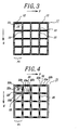
- Fig. 3 is a cross sectional view showing another embodiment of the honeycomb structural body according to the invention.
- the center portion 2a of the first wall portion 2 is formed by the sub material only, and the end portion 2b of the first wall portion 2 is formed by the main material.
- an entire first wall portion 12 may be formed by the sub material only.
- the honeycomb structural body according to the invention is used as the catalyst carrier for purifying the exhaust gas in the automobile, if use is made of the sub material having a larger mechanical strength than that of cordierite, it is possible to further improve a mechanical strength of the overall honeycomb structural body.
- a plurality of wall portions which construct the honeycomb structural bodies 1 and 11 shown in Figs. 1 and 3, comprise the second wall portions 3 and 13 made of the main material only.
- the second wall portions 3 and 13 are continuous respectively in Q direction of the cross portions 5, 15 and the honeycomb structural bodies 1 and 11. Therefore, a strength anisotropy in Q direction is generated in the honeycomb structural bodies 1 and 11, and thus it is possible to obtain an advantage such that a thermal expansion action in Q direction can be treated in the same manner as that of the honeycomb structural body made of the main material only.
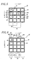
- Fig. 4 is a cross sectional view showing still another embodiment of the honeycomb structural body according to the invention.
- a honeycomb structural body 21 shown in Fig. 4 end portions 22b of a first wall portion 22 are formed by the main material as is the same as the end portions 2b of the first wall portion 2 in the honeycomb structural body 1 shown in Fig. 1.
- the cross portions 5 and 15 are adjacent to the first wall portions 1, 12 and the second wall portions 3, 13.
- all the wall portions adjacent to a cross portion 25 are constructed by the first wall portions 22. Therefore, a strength isotropy of the honeycomb structural body 21 is increased, and thus a mechanical strength thereof is further improved.
- Fig. 5 is a cross sectional view showing still another embodiment of the honeycomb structural body according to the invention.
- all the wall portions in P direction or in Q direction are constructed by the first wall portions.
- the wall portions of the honeycomb structural body in P direction may be constructed alternately by a first wall portion 35.
- Fig. 6 is a cross sectional view showing still another embodiment of the honeycomb structural body according to the invention.
- the main material and the sub material are stacked in such a manner that respective row portions P1 of the through holes is assumed as one cycle.
- the honeycomb structural body 31 shown in Fig. 5 they are stacked in such a manner that respective row portions P2 having a length twice as large as P1 is assumed as one cycle.
- the main material and the sub material are stacked in such a manner that the cycles P1 and P2 are mixed.
- the main material and the sub material, which construct the honeycomb structural body according to the invention are not necessarily formed by a single material, but use may be made of a mix material in which a plurality of materials are mixed according to the use application.
- the stack cycle P1 is divided into portions P1-a and P1-b at both ends of the center portion 2a of the first wall portion 2. Then, the portion P1-a is formed by a first main material, and the portion P1-b is formed by a second main material other than the first main material. In this case, it is possible to form the honeycomb structural body in which the first main material, the sub material and the second main material are cyclically stacked in this order.
- YSZ is used as the first main material
- lanthanum chromite is used as the second main material
- lanthanum zirconate is used as the sub material.
- the stack cycle P1 is divided into the portions P1-a and P1-b as mentioned above, and the stack cycle P2 is divided into portions P2-a and P2-b at both ends of a center portion 42a of a first wall portion 42. Then, the portions P1-a and P2-b are formed by the first main material, and the portions P1-b and P2-a are formed by the second main material other than the first main material. In this case, it is possible to obtain the honeycomb structural body in which the first main material/ the sub material/ the second main material/ the sub material are stacked as one cycle.
- a porous alumina 1 ⁇ having an average particle size of 1 ⁇ m as the first main material a porous alumina 2 ⁇ having an average particle size of 10 ⁇ m as the second main material and a dense alumina 3 ⁇ as the sub material.
- a porous alumina 1 ⁇ /the dense alumina 3 ⁇ / the porous alumina 2 ⁇ / the dense alumina 3 ⁇ are stacked as one cycle.
- a method of producing the honeycomb structural body is not limited particularly, but a following producing method is generally used. At first, raw material powders of the main material and the sub material are prepared and mixed to form a predetermined main material batch and sub material batch. Then, the main material batch and the sub material batch are filled in a plurality of cylinders, and then a honeycomb structural body is produced by means of a simultaneous extrusion forming method. Then, the thus produced honeycomb structural body is dried and then set in an electric furnace to perform a sintering by heat. After that, the honeycomb structural body can be obtained.
- the center portion of the first wall portion made of the sub material corresponds to the connection portion made of the main material.
- the honeycomb structural body having a structure shown in Fig. 1 was produced.
- the respective raw portions P1 of the through hole was divided into the portions P1-a and P1-b.
- the portion P1-a was formed by the first main material.
- the portion P1-b was formed by the second main material other than the first main material.
- 3 parts by weight of methylcellulose and 3 parts by weight of polyvinyl alcohol were mixed with respect to 100 parts by weight of lanthanum chromite powders having an average particle size of 3 ⁇ m to obtain a mixture.
- 14 parts by weight of water was added in the mixture and then the mixture with water was kneaded for 3 hours by means of a pressurized kneading apparatus to obtain a kneaded member.
- the kneaded member was set in a vacuum pug mil to produce a cylindrical first main material batch having a diameter of 80mm and a length of 300 mm.
- methylcellulose and 4 parts by weight of polyvinyl alcohol were mixed with respect to 100 parts by weight of 8 mol% yttria stabilized zirconia powders having an average particle size of 1.5 ⁇ m to obtain a mixture.
- 18 parts by weight of water was added in the mixture and then the mixture with water was kneaded for 3 hours by means of a pressurized kneading apparatus to obtain a kneaded member.
- the kneaded member was set in a vacuum pug mil to produce a cylindrical second main material batch having a diameter of 80mm and a length of 300 mm.
- the thus obtained batches were respectively filled in respective cylinder of a triaxial extrusion forming apparatus. Then, the batches were extruded under a condition such that extrusion speeds from respective batches were substantially constant by controlling an oil pressure of a plunger to obtain a honeycomb structural formed body.
- honeycomb structural formed body was set in a dryer to perform a drying operation at 80°C for 10 hours under a condition such that a moisture was suitably controlled. Then, the honeycomb structural formed body was set in an electric furnace. An atmosphere in the electric furnace was heated up to 1600°C by an ascending rate of 100°C/hours and then maintained at 1600°C for 3 hours so as to perform a sintering operation of the honeycomb structural formed body. After that, an atmosphere in the electric furnace was cooled by a descending rate of 200°C/hours. When a temperature in the electric furnace became at 100°C, a sintered body was picked up and the honeycomb structural body can be obtained.
- Outer dimensions of the sintered body were a length of 60mm and a breadth of 60mm, and a length L2 of the sintered body was 300 mm.
- the respective row portions P1 of the through hole were 2 mm, and a width (d) of the center portion 2a made of the sub material was 500 ⁇ m.
- a thickness of the first wall portion 2 and a thickness of the second wall portion 3 were 200 ⁇ m respectively.
- Sample A was obtained by cutting the thus obtained honeycomb structural body along L direction shown in Fig. 2 in such a manner that the number of the through holes 4 extended along L direction were 5 in a lengthwise direction and 10 in a breadthwise direction and a length was 100 mm.
- sample B was obtained by cutting the thus obtained honeycomb structural body along a perpendicular direction with respect to L direction shown in Fig. 2 in such a manner that the number of the through holes 4 extended along L direction were 20 in a lengthwise direction and 4 in a breadthwise direction and a length was 4mm. Then, a spalling test was performed by applying 10 heat cycle loads to the thus obtained samples A and B.
- one heat cycle load was assumed to be following steps of heating up to 1000°C by an ascending rate of 300°C/minute, keeping at 1000°C for 10 minutes and cooling up to 200°C by a descending rate of 300°C/minute.
- 4-point bending test was performed with respect to the sample A and the sample B before and after applying the heat cycle load. Then, a spalling resistance was estimated from a decreasing rate of a fracture strength after the heat cycle load. The results are shown in Table 1.
- the honeycomb structural body having a structure shown in Fig. 1 was produced.
- the center portion 2a of the first wall portion 2 was formed by the sub material
- the end portion 2b of the first wall portion 2 was formed by the main material.
- the thus obtained batches were respectively filled in respective cylinder of a biaxial extrusion forming apparatus. Then, the batches were extruded under a condition such that extrusion speeds from respective batches were substantially constant by controlling an oil pressure of a plunger to obtain a honeycomb structural formed body.
- honeycomb structural formed body was sintered in the same manner as that of the example 1 to obtain the honeycomb structural body.
- Outer dimensions of the sintered body were a length of 60 mm and a breadth of 60mm, and a length L2 of the sintered body was 300 mm.
- the respective row portions P1 of the through hole were 2.5 mm, and a width (d) of the center portion 2a made of the sub material was 0.5 mm.
- a thickness of the first wall portion 2 and a thickness of the second wall portion 3 were 200 ⁇ m respectively.
- Samples A and B were cut from the thus obtained honeycomb structural body in the same manner as that of the example 1.
- the spalling test was performed with respect to the samples A and B in the same manner as that of the example 1.
- the spalling resistance was estimated by the 4-point bending test before and after the heat cycle load.
- honeycomb structural body was produced in the same manner as that of the example 1 except that the sub material was not used, so that the honeycomb structural body, having the same structural as that of the example 1 except that the center portion of the first wall portion was not formed by the sub material, was obtained.
- Samples A and B were cut from the thus obtained honeycomb structural body in the same manner as that of the example 1.
- the 4-point bending tests for the samples A and B were performed before and after the heat cycle load as is the same as the example 1, and the spalling resistance was estimated from a decreasing rate of a fracture strength before and after the heat cycle load. The results are shown in Table 1.
- honeycomb structural body was produced in the same manner as that of the example 2 except that the sub material was not used, so that the honeycomb structural body, having the same structural as that of the example 2 except that the center portion of the first wall portion was not formed by the sub material, was obtained.
- the honeycomb structural body according to the invention shown by the examples 1 and 2 in which the center portion of the first wall portion was formed by the sub material such as yttria stabilized zirconia which improves the spalling resistance, does not decrease a fracture strength before and after the heat cycle load and has a high spalling resistance.
- the honeycomb structural body show by the comparative examples 1 and 2, in which the center portion of the first wall portion is not formed by the sub material, decreases a fracture strength before and after the heat cycle load and has a low spalling resistance.
- the honeycomb structural body of the invention if the honeycomb structural body is used for the catalyst carrier for purifying the exhaust gas of the automobile or for the electrochemical cell, it is possible to improve the properties such as the mechanical strength and the spalling resistance, which are the problems of the known honeycomb structural body, without affecting the other properties.
Landscapes
- Chemical & Material Sciences (AREA)
- Organic Chemistry (AREA)
- Engineering & Computer Science (AREA)
- Materials Engineering (AREA)
- Ceramic Engineering (AREA)
- Inorganic Chemistry (AREA)
- Chemical Kinetics & Catalysis (AREA)
- Structural Engineering (AREA)
- Catalysts (AREA)
- Exhaust Gas After Treatment (AREA)
- Fuel Cell (AREA)
Abstract
Description
| Fracture strength before heat cycle load (MPa) | Fracture strength after heat cycle load (MPa) | |||
| Sample A | Sample B | Sample A | Sample B | |
| Example 1 | 5.3 | 2.8 | 5.2 | 2.6 |
| Example 2 | 3.1 | 1.5 | 3.3 | 1.4 |
| Comparative Example 1 | 3.2 | 1.8 | 1.0 | 0.7 |
| Comparative Example 2 | 2.0 | 1.2 | 1.5 | 0.7 |
Claims (8)
- A honeycomb structural body having a plurality of wall portions and a plurality of cross portions, wherein a plurality of through holes are formed by the wall portions and the cross portions, comprising a structure such that:(1) the cross portions are made of a main material which constitutes the honeycomb structural body;(2) the wall portions have a first wall portion; and(3) a center portion of the first wall portion is made of a sub material which is different from the main material.
- The honeycomb structural body according to claim 1, wherein end portions of the first wall portion are made of the main material.
- The honeycomb structural body according to claim 1, wherein the entire first wall portion is made of the sub material.
- The honeycomb structural body according to claim 1, wherein a plurality of the wall portions have a second wall portion, the entire second wall portion is made of the main material, and the cross portion and the second wall portion are continuous in one direction.
- The honeycomb structural body according to claim 2, wherein all of the wall portions adjacent to the cross portion are the first wall portions.
- The honeycomb structural body according to claim 1, wherein the honeycomb structural body is formed by stacking the main material and the sub material.
- The honeycomb structural body according to claim 6, wherein the main material and the sub material are stacked in such a manner that respective rows or respective lines of the through holes is one cycle.
- A honeycomb structural body having a plurality of partition walls defining passages in the body, wherein the partition walls are made of a main material and a sub-material which is different from said main material and constitutes not more than 50 wt% of the body, at least a central part of the length of at least some of the partition walls being made of said sub-material.
Applications Claiming Priority (2)
| Application Number | Priority Date | Filing Date | Title |
|---|---|---|---|
| JP03950199A JP4471411B2 (en) | 1999-02-18 | 1999-02-18 | Honeycomb structure |
| JP3950199 | 1999-02-18 |
Publications (3)
| Publication Number | Publication Date |
|---|---|
| EP1029594A2 true EP1029594A2 (en) | 2000-08-23 |
| EP1029594A3 EP1029594A3 (en) | 2003-01-29 |
| EP1029594B1 EP1029594B1 (en) | 2009-04-15 |
Family
ID=12554804
Family Applications (1)
| Application Number | Title | Priority Date | Filing Date |
|---|---|---|---|
| EP00301128A Expired - Lifetime EP1029594B1 (en) | 1999-02-18 | 2000-02-15 | Honeycomb structural body |
Country Status (4)
| Country | Link |
|---|---|
| US (1) | US6482498B1 (en) |
| EP (1) | EP1029594B1 (en) |
| JP (1) | JP4471411B2 (en) |
| DE (1) | DE60041995D1 (en) |
Cited By (2)
| Publication number | Priority date | Publication date | Assignee | Title |
|---|---|---|---|---|
| WO2008079668A3 (en) * | 2006-12-21 | 2008-08-28 | Dow Global Technologies Inc | Improved soot filter |
| EP2161078A3 (en) * | 2008-09-05 | 2011-03-23 | Delphi Technologies, Inc. | Hydrocarbon reformer substrate having a graded structure for thermal control |
Families Citing this family (10)
| Publication number | Priority date | Publication date | Assignee | Title |
|---|---|---|---|---|
| JP4640903B2 (en) * | 2001-07-13 | 2011-03-02 | 日本碍子株式会社 | Honeycomb structure and manufacturing method thereof |
| CA2530933C (en) * | 2003-06-30 | 2011-10-25 | Japan Energy Corporation | Fuel cell with incorporated reformer for generating hydrogen |
| JP2008175517A (en) * | 2006-03-08 | 2008-07-31 | Ibiden Co Ltd | Cooler for baked object, calcination furnace, cooling method for ceramic baked object, and manufacturing method for honeycomb structure |
| US7820002B2 (en) * | 2006-11-16 | 2010-10-26 | Wycech Joseph S | Method for making a reception assembly and an reception assembly |
| JPWO2008146350A1 (en) * | 2007-05-25 | 2010-08-12 | イビデン株式会社 | Honeycomb structure and method for manufacturing honeycomb structure |
| JP2010227818A (en) * | 2009-03-26 | 2010-10-14 | Ngk Insulators Ltd | Honeycomb structure and honeycomb catalyst |
| JP5937381B2 (en) * | 2012-03-06 | 2016-06-22 | 日本碍子株式会社 | Honeycomb structure |
| US9945120B1 (en) * | 2017-05-03 | 2018-04-17 | Yu-Tsai Wu | Plastic form and manufacturing method thereof |
| US11285468B2 (en) * | 2017-11-24 | 2022-03-29 | Ngk Insulators, Ltd. | Honeycomb structure |
| US10886507B2 (en) * | 2018-06-15 | 2021-01-05 | Rivian Ip Holdings, Llc | Battery pack with laminates to reduce impact of side rupture and method of manufacturing same |
Family Cites Families (4)
| Publication number | Priority date | Publication date | Assignee | Title |
|---|---|---|---|---|
| GB1039752A (en) * | 1962-02-16 | 1966-08-24 | Crosby And Company Ltd | Improvements in or relating to cellular structures, for example for spacing two surfaces apart |
| US5277958A (en) * | 1990-01-02 | 1994-01-11 | Tomkins Keith A | Multiple-layer structures and joining method for honeycomb, foam and lightweight materials |
| US5655211A (en) * | 1992-04-22 | 1997-08-05 | Emitec Gesellschaft Fuer Emissionstechnologie | Electrically conductive honeycomb structure, particularly for electrically heatable catalytic converters for motor vehicles and method for producing a honeycomb body |
| AU1731195A (en) * | 1994-01-27 | 1995-08-15 | Engelhard Corporation | Process for recovering catalyst supports |
-
1999
- 1999-02-18 JP JP03950199A patent/JP4471411B2/en not_active Expired - Fee Related
-
2000
- 2000-02-11 US US09/502,792 patent/US6482498B1/en not_active Expired - Fee Related
- 2000-02-15 DE DE60041995T patent/DE60041995D1/en not_active Expired - Lifetime
- 2000-02-15 EP EP00301128A patent/EP1029594B1/en not_active Expired - Lifetime
Cited By (2)
| Publication number | Priority date | Publication date | Assignee | Title |
|---|---|---|---|---|
| WO2008079668A3 (en) * | 2006-12-21 | 2008-08-28 | Dow Global Technologies Inc | Improved soot filter |
| EP2161078A3 (en) * | 2008-09-05 | 2011-03-23 | Delphi Technologies, Inc. | Hydrocarbon reformer substrate having a graded structure for thermal control |
Also Published As
| Publication number | Publication date |
|---|---|
| DE60041995D1 (en) | 2009-05-28 |
| EP1029594B1 (en) | 2009-04-15 |
| JP2000237603A (en) | 2000-09-05 |
| EP1029594A3 (en) | 2003-01-29 |
| US6482498B1 (en) | 2002-11-19 |
| JP4471411B2 (en) | 2010-06-02 |
Similar Documents
| Publication | Publication Date | Title |
|---|---|---|
| US4839214A (en) | Ceramic rotors for pressure wave superchargers and production thereof | |
| US6482498B1 (en) | Honeycomb structural body | |
| US7803312B2 (en) | Ceramic honeycomb structural body and method of manufacturing the same | |
| EP1200369B1 (en) | Low expansion, high porosity, high strength cordierite body and method | |
| US7981496B2 (en) | Honeycomb structured body | |
| EP1245262B1 (en) | Method of manufacturing an exhaust gas purifying filter | |
| EP1707545B1 (en) | Honeycomb structure and process for producing the same | |
| US8584375B2 (en) | Method of drying honeycomb article, and drying apparatus therefor | |
| US20060292341A1 (en) | Honeycomb structure | |
| US7833936B2 (en) | Honeycomb structure, method for producing the same, and exhaust emission purification apparatus | |
| US20080241444A1 (en) | Honeycomb structure and manufacturing method therefor | |
| EP1977828A1 (en) | Catalyst carrier and exhaust-gas treating device | |
| EP1736459A1 (en) | Honeycomb structured body | |
| US20060292336A1 (en) | Honeycomb structured body and method of manufacturing the same | |
| EP1923125A1 (en) | Honeycomb structured body and method for manufacturing the same | |
| KR930016376A (en) | Manufacturing method of porous ceramic for diesel dust filter | |
| US6593261B2 (en) | Silicon nitride porous body and its production process | |
| US10989092B2 (en) | Honeycomb structured body | |
| US7344770B2 (en) | Ceramics honeycomb structural body and method of manufacturing the structural body | |
| EP3689459A1 (en) | Honeycomb catalyst | |
| EP1698397A1 (en) | Honeycomb structure | |
| EP4691637A1 (en) | Honeycomb ceramic carrier, preparation method therefor, and catalytic body containing honeycomb ceramic carrier | |
| US11187130B2 (en) | Honeycomb structured body | |
| JP3126939B2 (en) | Manufacturing method of laminated sintered body | |
| EP1547743B1 (en) | Method for manufacturing honeycomb structure |
Legal Events
| Date | Code | Title | Description |
|---|---|---|---|
| PUAI | Public reference made under article 153(3) epc to a published international application that has entered the european phase |
Free format text: ORIGINAL CODE: 0009012 |
|
| AK | Designated contracting states |
Kind code of ref document: A2 Designated state(s): AT BE CH CY DE DK ES FI FR GB GR IE IT LI LU MC NL PT SE |
|
| AX | Request for extension of the european patent |
Free format text: AL;LT;LV;MK;RO;SI |
|
| PUAL | Search report despatched |
Free format text: ORIGINAL CODE: 0009013 |
|
| AK | Designated contracting states |
Designated state(s): AT BE CH CY DE DK ES FI FR GB GR IE IT LI LU MC NL PT SE |
|
| AX | Request for extension of the european patent |
Extension state: AL LT LV MK RO SI |
|
| RIC1 | Information provided on ipc code assigned before grant |
Ipc: 7B 28B 3/20 B Ipc: 7B 01J 35/04 B Ipc: 7C 04B 38/00 A |
|
| 17P | Request for examination filed |
Effective date: 20030721 |
|
| AKX | Designation fees paid |
Designated state(s): DE FR GB |
|
| GRAP | Despatch of communication of intention to grant a patent |
Free format text: ORIGINAL CODE: EPIDOSNIGR1 |
|
| GRAS | Grant fee paid |
Free format text: ORIGINAL CODE: EPIDOSNIGR3 |
|
| GRAA | (expected) grant |
Free format text: ORIGINAL CODE: 0009210 |
|
| AK | Designated contracting states |
Kind code of ref document: B1 Designated state(s): DE FR GB |
|
| REG | Reference to a national code |
Ref country code: GB Ref legal event code: FG4D |
|
| REF | Corresponds to: |
Ref document number: 60041995 Country of ref document: DE Date of ref document: 20090528 Kind code of ref document: P |
|
| PLBE | No opposition filed within time limit |
Free format text: ORIGINAL CODE: 0009261 |
|
| STAA | Information on the status of an ep patent application or granted ep patent |
Free format text: STATUS: NO OPPOSITION FILED WITHIN TIME LIMIT |
|
| 26N | No opposition filed |
Effective date: 20100118 |
|
| PGFP | Annual fee paid to national office [announced via postgrant information from national office to epo] |
Ref country code: FR Payment date: 20140211 Year of fee payment: 15 |
|
| PGFP | Annual fee paid to national office [announced via postgrant information from national office to epo] |
Ref country code: GB Payment date: 20140212 Year of fee payment: 15 |
|
| PGFP | Annual fee paid to national office [announced via postgrant information from national office to epo] |
Ref country code: DE Payment date: 20140417 Year of fee payment: 15 |
|
| REG | Reference to a national code |
Ref country code: DE Ref legal event code: R119 Ref document number: 60041995 Country of ref document: DE |
|
| GBPC | Gb: european patent ceased through non-payment of renewal fee |
Effective date: 20150215 |
|
| REG | Reference to a national code |
Ref country code: FR Ref legal event code: ST Effective date: 20151030 |
|
| PG25 | Lapsed in a contracting state [announced via postgrant information from national office to epo] |
Ref country code: GB Free format text: LAPSE BECAUSE OF NON-PAYMENT OF DUE FEES Effective date: 20150215 Ref country code: DE Free format text: LAPSE BECAUSE OF NON-PAYMENT OF DUE FEES Effective date: 20150901 |
|
| PG25 | Lapsed in a contracting state [announced via postgrant information from national office to epo] |
Ref country code: FR Free format text: LAPSE BECAUSE OF NON-PAYMENT OF DUE FEES Effective date: 20150302 |