EP1029254B1 - Improved ophthalmic lens - Google Patents
Improved ophthalmic lens Download PDFInfo
- Publication number
- EP1029254B1 EP1029254B1 EP98949831.6A EP98949831A EP1029254B1 EP 1029254 B1 EP1029254 B1 EP 1029254B1 EP 98949831 A EP98949831 A EP 98949831A EP 1029254 B1 EP1029254 B1 EP 1029254B1
- Authority
- EP
- European Patent Office
- Prior art keywords
- lens
- merit function
- function
- merit
- modified
- Prior art date
- Legal status (The legal status is an assumption and is not a legal conclusion. Google has not performed a legal analysis and makes no representation as to the accuracy of the status listed.)
- Expired - Lifetime
Links
Images


Classifications
-
- G—PHYSICS
- G02—OPTICS
- G02C—SPECTACLES; SUNGLASSES OR GOGGLES INSOFAR AS THEY HAVE THE SAME FEATURES AS SPECTACLES; CONTACT LENSES
- G02C7/00—Optical parts
- G02C7/02—Lenses; Lens systems ; Methods of designing lenses
- G02C7/024—Methods of designing ophthalmic lenses
- G02C7/028—Special mathematical design techniques
-
- G—PHYSICS
- G02—OPTICS
- G02C—SPECTACLES; SUNGLASSES OR GOGGLES INSOFAR AS THEY HAVE THE SAME FEATURES AS SPECTACLES; CONTACT LENSES
- G02C2202/00—Generic optical aspects applicable to one or more of the subgroups of G02C7/00
- G02C2202/22—Correction of higher order and chromatic aberrations, wave front measurement and calculation
Definitions
- the present invention relates to an improved single vision ophthalmic lens.
- the invention particularly relates to methods of surface correction to improve the optical performance of a single vision ophthalmic lens by reducing optical aberrations, such as those associated with power and astigmatic errors, together with lenses produced by such methods.
- prior art attempts introduced corrections by aspherising one or both of the lens surfaces for spherical or toric corrections.
- typical prior art methods have relied on aspherising the two principle toric meridians of the lens back surface, improving the optical performance of these meridians independent of each other. This method has proven to be deficient in that the regions between the two principle meridians are not sufficiently optically optimised in the same way as the vision along the principle meridians.
- EP-A-0560999 discloses an eyeglass lens for eyesight correction which is reduced in lens thickness thereby to decrease the weight and which is improved in optical properties by removing the aberration.
- the present invention provides a method according to claim 1 of designing an ophthalmic lens element having a first surface and an atoroidal or generally aspheric second surface. Preferred features are defined in the dependent claims.
- 'atoroidal surface' or 'atoric surface' we mean a surface being of a generally toric nature at the intersection of the surface and the optical axis of the lens element, but which departs from a circular section along any radial line from the surface centre. In this respect, it will be appreciated that this surface is described in the present invention by a symmetric polynomial. Also, by the term 'effective surface' we mean at least that area of the surface of a lens remaining after the edging and finishing of the lens.
- 'astigmatic correction' we mean the wearer's prescribed cylinder correction and the associated axis of this correction.
- 'astigmatism' or 'surface astigmatism' we mean a measure of the degree to which the curvature of the lens varies among intersecting planes which are normal to the surface of the lens at a point on the surface.
- 'generally aspheric surface' we mean a surface bearing no particular cylinder and whose surface departs from a circular section along any radial line from the surface centre. It will be appreciated that in the present invention, such a surface is described by a symmetric polynomial such that C 2,0 and C 0,2 are substantially equal. In this respect, C 2,0 and C 0,2 may differ to correct for optical performance, but are substantially different to the wearer's prescription cylinder needs.
- a particular combination of optical aberrations may be minimised over substantially the entire aperture of the ophthalmic lens element.
- a particular measure of optical aberrations may be controlled, so that it increases gradually from the optical centre to the periphery of the ophthalmic lens element but stays below a certain threshold known to be just detectable by most wearers.
- the purpose of such an alternative is to allow for the provision of a lens element with a cosmetic improvement, such as a thinner and lighter lens, without any noticeable degradation in optical performance.
- the first surface of the ophthalmic lens element of the present invention may be a spherical surface, a toric surface, or a rotationally symmetric aspheric surface, chosen to produce the best optical and/or cosmetic performance for the wearer's overall prescription.
- first surface referred to above may be either the front surface or the back surface of the lens element, which implies that the second surface will conversely be either of the back surface or the front surface respectively of the lens element.
- the first surface may be the front surface, which then becomes fixed while the modifications are worked to the back surface.
- the front surface may then be any of a spherical surface, a toric surface, or a rotationally symmetric aspheric surface, as mentioned above.
- it is then the back surface that has an atoroidal or generally aspheric shape and is shaped according to the modified surface function according to the present invention.
- the first surface may be the back surface, which then becomes fixed while the modifications are worked to the front surface.
- the back surface may then be any of a spherical surface, a toric surface, or a rotationally symmetric aspheric surface, as described above.
- it will be the front surface that has an atoroidal or generally aspheric shape and is shaped according to the modified surface function according to the present invention.
- the ophthalmic lens element may include a front, generally spherical surface (or a front, toric surface) providing the overall base curve (or for the toric surface, providing a cylinder correction) required to correct for the wearer's mean power error in combination with the mean curvature of the back surface.
- the back surface may then have an atoroidal or generally aspheric shape and be shaped according to the modified surface function according to the present invention.
- the front surface may additionally be flattened to provide a cosmetic benefit, and the mean power of the back surface may be adjusted to provide the required lens power.
- the front surface in this form may be selected to be an aspheric surface to improve the optical performance which may be degraded during the flattening of the lens form, as it would depart from best form for the given prescription correction.
- the improved ophthalmic lens may include a first surface wafer having a first lens surface, and a second surface wafer having a second lens surface.
- the second surface may then have an atoroidal or generally aspheric shape and be shaped according to the modified surface function according to the present invention.
- an ophthalmic lens element in the form of a second surface wafer for use with a first surface wafer, the second surface wafer having a front surface and a back surface.
- the front surface of the second surface wafer may be shaped according to the modified surface function according to the present invention.
- the back surface of the second surface wafer may then be suitable for combination with the first surface wafer.
- the present invention provides a method of designing an ophthalmic lens element. The method includes the steps of:
- the method may be altered such that the selection of a merit function is the selection of a merit function modified to relate at least one optical aberration characteristic together with at least one lens cosmetic characteristic to a merit figure.
- a modified merit function may operate, for example, to modify the lens thickness, for example towards the periphery of the lens.
- M 1 ⁇ ⁇ rms blur ⁇ 2
- M 2 ⁇ ⁇ mpe 2 + cyl error 2 ⁇
- M 3 ⁇ ⁇ 1 16 ⁇ mpe 2 + cyl error 2 ⁇
- M 4 ⁇ ⁇ mpe 2 + 1 16 ⁇ cyl error 2 ⁇
- M 1 represents a simple merit function based solely on rms blur, and is a preferred merit function for use in the present invention.
- M 2 represents a merit function which provides a balanced weighting between the impact of mean power error and cyl error.
- the modes M 3 and M 4 represent "minimum astigmatic error” and “minimum mean power error” strategies respectively.
- a term may be included in the merit function that represents the cosmetics of the lens.
- M a modified merit function
- M * M + ⁇ ⁇ ⁇ ⁇ 2 ⁇ V ⁇ ⁇ r 2 2
- ⁇ ⁇ denotes the number of sample eye rotations ⁇ considered in M
- r is a specified lens radius
- V is the lens volume out to the radius r.
- the factor ⁇ is seen to be a weighting on the average lens thickness.
- the ophthalmic lens element of the present invention may be formed from glass or from a polymeric article.
- the polymeric article where applicable, may be of any suitable type.
- a polycarbonate for example a material of the diallyl glycol carbonate type, may be used.
- the polymeric article may be formed from cross-linkable polymeric casting compositions, such as described in the applicant's United States patent 4,912,155 , United States patent Application 07/781,392 , Australian Patent applications 50581/93 and 50582/93 , or its European patent 453159A2 .
- Such cross-linkable polymeric casting compositions may include a diacrylate or dimethacrylate monomer (such as polyoxyalkylene glycol diacrylate or dimethacrylate or a bisphenol fluorene diacrylate or dimethacrylate) and a polymerisable comonomer, for example methacrylates, acrylates, vinyls, vinyl ethers, allyls, aromatic olefins, ethers, polythiols and the like.
- a diacrylate or dimethacrylate monomer such as polyoxyalkylene glycol diacrylate or dimethacrylate or a bisphenol fluorene diacrylate or dimethacrylate
- a polymerisable comonomer for example methacrylates, acrylates, vinyls, vinyl ethers, allyls, aromatic olefins, ethers, polythiols and the like.
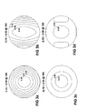
- Figure 1 illustrates two lenses of the present invention having positive sphere powers of 3.75 D.
- the front surface of these lenses is a sphere of 4.63 D.
- the back surface is atoric optimised for the cylinder values of -0.50 D in Figure 1(a), (b), (c) and -2.50 D in Figure 1(d), (e), (f) .
- the coefficients of the 4 th order symmetric polynomial describing the form of the respective atoric surfaces are given in Tables 1 and 2.
- Figures 1(a) and (c) show the back surface astigmatism contour plot
- Figures 1 (b) and (d) display the mean back surface power
- Figures 1 (c) and (f) show the ray traced optical RMS blur created by each of these lenses respectively.
- Figure 2 illustrates two lenses of the present invention having negative sphere powers of -5.75 D.
- the front surface of these lenses is a sphere of 1.32 D.
- the back surface is atoric optimised for the cylinder values of -0.50 D in Figure 1(a), (b), (c) and -2.50 D in Figure 1 (d), (e), (f) .
- the coefficients of the 4 th order symmetric polynomial describing the form of the respective atoric surfaces are given in Tables 3 and 4.
- Figures 1(a) and (c) show the back surface astigmatism contour plot
- Figures 1 (b) and (d) display the mean back surface power
- Figures 1(c) and (f) show the ray traced optical RMS blur created by each of these lenses respectively.
- Table 3 Coefficients of the symmetric polynomial Optimised for -5.75/-0.50 X 2 Y 2 6.15E-03 6.58E-03 X 4 X 2 Y 2 Y 4 -6.81 E-08 4.93E-08 -7.62E-09
- Table 4 Coefficients of the symmetric polynomial Optimised for -5.75/-2.50 X 2 Y 2 6.15E-031 8.29E-03 X 4 X 2 Y 2 Y 4 -5.24E-08 3.57E-07 4.12E-07
- Figure 3 shows the optical RMS blur contours for the conventional toric lenses of the same prescriptions as those in Figures 1 and 2 .
Landscapes
- Physics & Mathematics (AREA)
- Health & Medical Sciences (AREA)
- Ophthalmology & Optometry (AREA)
- Mathematical Physics (AREA)
- General Health & Medical Sciences (AREA)
- General Physics & Mathematics (AREA)
- Optics & Photonics (AREA)
- Lenses (AREA)
- Eyeglasses (AREA)
Description
- The present invention relates to an improved single vision ophthalmic lens. The invention particularly relates to methods of surface correction to improve the optical performance of a single vision ophthalmic lens by reducing optical aberrations, such as those associated with power and astigmatic errors, together with lenses produced by such methods.
- Conventional single vision lenses do not adequately correct for optical aberrations apparent to the wearer when viewing objects, through the lens, at oblique angles. This results from the lens surfaces not being the ideal shape to fully correct for the wearer's specific needs of power, cylinder correction and fitting requirements for off-axis vision.
- Attempts have been made to correct such errors in the prior art with limited success, and have most often resulted in compromises that either do not fully correct the entire lens surface or that inadequately address the optical aberrations and errors.
- Typically, prior art attempts introduced corrections by aspherising one or both of the lens surfaces for spherical or toric corrections. For example, typical prior art methods have relied on aspherising the two principle toric meridians of the lens back surface, improving the optical performance of these meridians independent of each other. This method has proven to be deficient in that the regions between the two principle meridians are not sufficiently optically optimised in the same way as the vision along the principle meridians.
- Other methods have typically included minimising astigmatism on a grid of points on the lens surface using optical ray tracing techniques, following which a twice continuously differentiable spline surface (satisfying the data at each point) is fitted. However, it is only possible to satisfy these conditions for a limited range of simple surfaces that cover only a fraction of all surfaces that are of interest to the ophthalmic industry. In other cases, such an approach normally requires the fitting of a smoothing spline surface in an attempt to approximate the calculated data at each point, without satisfying it exactly. As a result, the optics of such a surface often significantly deviates from the optimal case.
-
EP-A-0560999 discloses an eyeglass lens for eyesight correction which is reduced in lens thickness thereby to decrease the weight and which is improved in optical properties by removing the aberration. - It is an object of the present invention to provide an improved single vision ophthalmic lens that overcomes the difficulties identified above with prior art single vision ophthalmic lenses.
- The present invention provides a method according to claim 1 of designing an ophthalmic lens element having a first surface and an atoroidal or generally aspheric second surface. Preferred features are defined in the dependent claims.
- It has been found that in order to reduce optical aberrations visible to wearers, it is necessary to apply the appropriate corrections over substantially the entire ophthalmic lens element, rather than just the two principle cylinder meridians. This has the beneficial effect of making a larger area of the lens surface to have tolerable levels of optical aberrations.
- Before turning to a general description of various aspects of the present invention, it will be instructive to provide some definitions for various terms used above. In this respect, by the term 'lens element' we mean all forms of individual refractive optical bodies employed in the ophthalmic arts, including, but not limited to, lenses, lens wafers and semi-finished lens blanks requiring further finishing to a particular patient's prescription. Also included are formers used in the manufacture of single vision glass lenses and moulds for the casting of single vision lenses in polymeric material.
- Further, by the terms 'atoroidal surface' or 'atoric surface' we mean a surface being of a generally toric nature at the intersection of the surface and the optical axis of the lens element, but which departs from a circular section along any radial line from the surface centre. In this respect, it will be appreciated that this surface is described in the present invention by a symmetric polynomial. Also, by the term 'effective surface' we mean at least that area of the surface of a lens remaining after the edging and finishing of the lens.
- In the following description, further terms will be used that may also require definition. In particular, by the term 'astigmatic correction' we mean the wearer's prescribed cylinder correction and the associated axis of this correction. Also, by the terms 'astigmatism' or 'surface astigmatism' we mean a measure of the degree to which the curvature of the lens varies among intersecting planes which are normal to the surface of the lens at a point on the surface.
- Finally, by the term 'generally aspheric surface' we mean a surface bearing no particular cylinder and whose surface departs from a circular section along any radial line from the surface centre. It will be appreciated that in the present invention, such a surface is described by a symmetric polynomial such that C2,0 and C0,2 are substantially equal. In this respect, C2,0 and C0,2 may differ to correct for optical performance, but are substantially different to the wearer's prescription cylinder needs.
- Turning now to a general description of the invention, in one preferred form a particular combination of optical aberrations may be minimised over substantially the entire aperture of the ophthalmic lens element. Alternatively, a particular measure of optical aberrations may be controlled, so that it increases gradually from the optical centre to the periphery of the ophthalmic lens element but stays below a certain threshold known to be just detectable by most wearers. The purpose of such an alternative is to allow for the provision of a lens element with a cosmetic improvement, such as a thinner and lighter lens, without any noticeable degradation in optical performance.
- The first surface of the ophthalmic lens element of the present invention may be a spherical surface, a toric surface, or a rotationally symmetric aspheric surface, chosen to produce the best optical and/or cosmetic performance for the wearer's overall prescription.
- It should be noted that the first surface referred to above may be either the front surface or the back surface of the lens element, which implies that the second surface will conversely be either of the back surface or the front surface respectively of the lens element.
- Thus, the first surface may be the front surface, which then becomes fixed while the modifications are worked to the back surface. The front surface may then be any of a spherical surface, a toric surface, or a rotationally symmetric aspheric surface, as mentioned above. In this form, it is then the back surface that has an atoroidal or generally aspheric shape and is shaped according to the modified surface function according to the present invention.
- Alternatively, the first surface may be the back surface, which then becomes fixed while the modifications are worked to the front surface. The back surface may then be any of a spherical surface, a toric surface, or a rotationally symmetric aspheric surface, as described above. In this form, it will be the front surface that has an atoroidal or generally aspheric shape and is shaped according to the modified surface function according to the present invention.
- In a preferred form, the ophthalmic lens element may include a front, generally spherical surface (or a front, toric surface) providing the overall base curve (or for the toric surface, providing a cylinder correction) required to correct for the wearer's mean power error in combination with the mean curvature of the back surface. The back surface may then have an atoroidal or generally aspheric shape and be shaped according to the modified surface function according to the present invention.
- In this form, the front surface may additionally be flattened to provide a cosmetic benefit, and the mean power of the back surface may be adjusted to provide the required lens power. Alternatively, the front surface in this form may be selected to be an aspheric surface to improve the optical performance which may be degraded during the flattening of the lens form, as it would depart from best form for the given prescription correction.
- In another form, the improved ophthalmic lens may include a first surface wafer having a first lens surface, and a second surface wafer having a second lens surface. As above, the second surface may then have an atoroidal or generally aspheric shape and be shaped according to the modified surface function according to the present invention.
- Alternatively, there may further be provided an ophthalmic lens element in the form of a second surface wafer for use with a first surface wafer, the second surface wafer having a front surface and a back surface. The front surface of the second surface wafer may be shaped according to the modified surface function according to the present invention. The back surface of the second surface wafer may then be suitable for combination with the first surface wafer.
- In relation to the modification to be made to the second surface of the ophthalmic lens element of the present invention (in terms of it being described by a symmetric polynomial whose coefficients have been chosen to minimise a merit function constructed of the sum of a particular optical aberration over substantially the entire surface thereof), the present invention provides a method of designing an ophthalmic lens element. The method includes the steps of:
- selecting a base surface function for the second lens surface in the form of an nth order symmetric polynomial of the form

- selecting a merit function relating to at least one optical aberration characteristic of the lens that needs to be minimised;
- computing the coefficients of the symmetric polynomial surface Ck-j,j that minimise the merit function over the substantially entire surface of the ophthalmic lens element to generate a modified surface function; and
- fabricating an ophthalmic lens element having a second lens surface shaped according to the modified surface function.
- Alternatively, the method may be altered such that the selection of a merit function is the selection of a merit function modified to relate at least one optical aberration characteristic together with at least one lens cosmetic characteristic to a merit figure. Such a modified merit function may operate, for example, to modify the lens thickness, for example towards the periphery of the lens.
- In considering the types of merit functions that may be used in this method, it should firstly be noted that there are a number of measures of the lens optical aberrations as seen by the wearer, such as:


where ε is the focal error matrix that may be written as:
where ε12 = ε21 by the choice of the orthornormal basis set. - Referring to these lens optical aberrations, four possible merit functions that may be utilised in the above method, depending upon the specific application of the optimised lens, are as follows:


where summations are over a number of sample eye rotations θ. These sample eye rotations are selected along a set of meridians covering substantially the entire surface of the lens element. - In relation to these merit functions, M1 represents a simple merit function based solely on rms blur, and is a preferred merit function for use in the present invention. M2 represents a merit function which provides a balanced weighting between the impact of mean power error and cyl error. The modes M3 and M4 represent "minimum astigmatic error" and "minimum mean power error" strategies respectively.
- In a still further embodiment, a term may be included in the merit function that represents the cosmetics of the lens. For example, instead of using any merit function, M , alone, a modified merit function may be defined by:

where ηθ denotes the number of sample eye rotations θ considered in M , r is a specified lens radius, and V is the lens volume out to the radius r. The factor λ is seen to be a weighting on the average lens thickness. - The ophthalmic lens element of the present invention may be formed from glass or from a polymeric article. The polymeric article, where applicable, may be of any suitable type. A polycarbonate, for example a material of the diallyl glycol carbonate type, may be used. The polymeric article may be formed from cross-linkable polymeric casting compositions, such as described in the applicant's United States patent
4,912,155 , United States patent Application07/781,392 , Australian Patent applications50581/93 50582/93 453159A2 - The present invention will now be described with reference to a series of examples and accompanying illustrations. However, it is to be appreciated that the following description is not to limit the generality of the above description.
-
Figure 1 illustrates two lenses of the present invention having positive sphere powers of 3.75 D. The front surface of these lenses is a sphere of 4.63 D. The back surface is atoric optimised for the cylinder values of -0.50 D inFigure 1(a), (b), (c) and -2.50 D inFigure 1(d), (e), (f) . The coefficients of the 4th order symmetric polynomial describing the form of the respective atoric surfaces are given in Tables 1 and 2.Figures 1(a) and (c) show the back surface astigmatism contour plot,Figures 1 (b) and (d) display the mean back surface power, whileFigures 1 (c) and (f) show the ray traced optical RMS blur created by each of these lenses respectively. Contours are incremented by 0.25 D and the diameter of the circle is 60 mm in all the Figures.Table 1: Coefficients of the symmetric polynomial Optimised for 3.75/-0.50 X2 Y2 1.23E-03 1.66E-03 X4 X2Y2 Y4 2.79E-07 4.45E-07 2.16E-07 Table-2: Coefficients of the symmetric polynomial Optimised for 3.75/-2.50 X2 Y2 1.23E-03 3.36E-03 X4 X2Y2 Y4 2.96E-07 2.22E-07 5.13E-08 -
Figure 2 illustrates two lenses of the present invention having negative sphere powers of -5.75 D. The front surface of these lenses is a sphere of 1.32 D. The back surface is atoric optimised for the cylinder values of -0.50 D inFigure 1(a), (b), (c) and -2.50 D inFigure 1 (d), (e), (f) . The coefficients of the 4th order symmetric polynomial describing the form of the respective atoric surfaces are given in Tables 3 and 4.Figures 1(a) and (c) show the back surface astigmatism contour plot,Figures 1 (b) and (d) display the mean back surface power, whileFigures 1(c) and (f) show the ray traced optical RMS blur created by each of these lenses respectively. Contours are incremented by 0.25 D in all figures.Table 3: Coefficients of the symmetric polynomial Optimised for -5.75/-0.50 X2 Y2 6.15E-03 6.58E-03 X4 X2Y2 Y4 -6.81 E-08 4.93E-08 -7.62E-09 Table 4: Coefficients of the symmetric polynomial Optimised for -5.75/-2.50 X2 Y2 6.15E-031 8.29E-03 X4 X2Y2 Y4 -5.24E-08 3.57E-07 4.12E-07 -
Figure 3 shows the optical RMS blur contours for the conventional toric lenses of the same prescriptions as those inFigures 1 and2 . - Finally, it will be appreciated that there may be other variations and modifications made to the features described above, which may also be within the scope of the present invention as defined in the attached claims.
Claims (4)
- A method of designing a single vision ophthalmic lens element having a first surface and an atoroidal or generally aspheric second surface, the method including the steps of:selecting a base surface function for the second lens surface in the form of an nth order symmetric polynomial of the form
 selecting a merit function relating to at least one optical aberration characteristic of the lens that needs to be minimised;computing the coefficients of the symmetric polynomial surface Ck-j,j that minimise the merit function over the substantially entire surface of the ophthalmic lens element to generate a modified surface function; andfabricating a single vision ophthalmic lens element having a second lens surface shaped according to the modified surface function;wherein the merit function is selected from the group of merit functions comprising:


where summations are over a number of sample eye rotations θ, the sample eye rotations being selected along a set of meridians covering substantially the entire surface of the lens element. - A method according to claim 1, wherein the selection of a merit function is the selection of a merit function modified to relate at least one optical aberration characteristic together with at least one lens cosmetic characteristic to a merit figure.
- A method according to claim 1 wherein the modified merit function operates to modify the lens thickness towards the periphery of the lens.
- A method according to claim 1 or claim 2 wherein a term is included in the merit function that represents the cosmetics of the lens, a modified merit function being defined by:

where M represents any merit function, ηø denotes the number of sample eye rotations θ considered in M, r is a specified lens radius, V is the lens volume out to the radius r, and the factor λ is a weighting on the average lens thickness.
Priority Applications (1)
| Application Number | Priority Date | Filing Date | Title |
|---|---|---|---|
| EP14179453.7A EP2821840B1 (en) | 1997-11-03 | 1998-10-23 | Improved ophthalmic lens |
Applications Claiming Priority (3)
| Application Number | Priority Date | Filing Date | Title |
|---|---|---|---|
| AUPP016197 | 1997-11-03 | ||
| AUPP0161A AUPP016197A0 (en) | 1997-11-03 | 1997-11-03 | Improved ophthalmic lens |
| PCT/AU1998/000881 WO1999023526A1 (en) | 1997-11-03 | 1998-10-23 | Improved ophthalmic lens |
Related Child Applications (2)
| Application Number | Title | Priority Date | Filing Date |
|---|---|---|---|
| EP14179453.7A Division EP2821840B1 (en) | 1997-11-03 | 1998-10-23 | Improved ophthalmic lens |
| EP14179453.7A Division-Into EP2821840B1 (en) | 1997-11-03 | 1998-10-23 | Improved ophthalmic lens |
Publications (3)
| Publication Number | Publication Date |
|---|---|
| EP1029254A1 EP1029254A1 (en) | 2000-08-23 |
| EP1029254A4 EP1029254A4 (en) | 2008-11-05 |
| EP1029254B1 true EP1029254B1 (en) | 2014-10-08 |
Family
ID=3804441
Family Applications (2)
| Application Number | Title | Priority Date | Filing Date |
|---|---|---|---|
| EP14179453.7A Expired - Lifetime EP2821840B1 (en) | 1997-11-03 | 1998-10-23 | Improved ophthalmic lens |
| EP98949831.6A Expired - Lifetime EP1029254B1 (en) | 1997-11-03 | 1998-10-23 | Improved ophthalmic lens |
Family Applications Before (1)
| Application Number | Title | Priority Date | Filing Date |
|---|---|---|---|
| EP14179453.7A Expired - Lifetime EP2821840B1 (en) | 1997-11-03 | 1998-10-23 | Improved ophthalmic lens |
Country Status (6)
| Country | Link |
|---|---|
| US (1) | US6305800B1 (en) |
| EP (2) | EP2821840B1 (en) |
| AU (2) | AUPP016197A0 (en) |
| CA (1) | CA2306902A1 (en) |
| ES (1) | ES2564551T3 (en) |
| WO (1) | WO1999023526A1 (en) |
Cited By (1)
| Publication number | Priority date | Publication date | Assignee | Title |
|---|---|---|---|---|
| EP4266116A1 (en) * | 2022-04-19 | 2023-10-25 | Carl Zeiss Vision International GmbH | Spectacle lens for optimized myopia control |
Families Citing this family (35)
| Publication number | Priority date | Publication date | Assignee | Title |
|---|---|---|---|---|
| AUPQ065599A0 (en) * | 1999-05-31 | 1999-06-24 | Sola International Holdings Ltd | Progressive lens |
| US6343860B1 (en) | 1999-08-26 | 2002-02-05 | Greenhouse Grown Products, Inc. | Toric-shaped lenses and goggle assembly |
| JP3869624B2 (en) * | 2000-05-10 | 2007-01-17 | ペンタックス株式会社 | Single focus spectacle lens design method, manufacturing method, and manufacturing system |
| JP4219546B2 (en) | 2000-10-17 | 2009-02-04 | セイコーオプティカルプロダクツ株式会社 | Eyeglass lenses |
| BRPI0214533B1 (en) * | 2001-12-05 | 2020-03-17 | Carl Zeiss Vision Australia Holdings Ltd. | PROGRESSIVE OPHTHALMIC LENS ELEMENT, SERIES OF PROGRESSIVE OPHTHALMIC LENS ELEMENTS AND METHOD OF DESIGNING A PROGRESSIVE OPHTHALMIC LENS ELEMENT |
| US6554427B1 (en) | 2001-12-11 | 2003-04-29 | Johnson & Johnson Vision Care, Inc. | Methods for designing contact lenses |
| SE0203564D0 (en) | 2002-11-29 | 2002-11-29 | Pharmacia Groningen Bv | Multifocal opthalmic lens |
| US7896916B2 (en) | 2002-11-29 | 2011-03-01 | Amo Groningen B.V. | Multifocal ophthalmic lens |
| GB0303193D0 (en) * | 2003-02-12 | 2003-03-19 | Guillon Michael | Methods & lens |
| JP3814257B2 (en) * | 2003-03-03 | 2006-08-23 | ペンタックス株式会社 | Aspheric spectacle lens |
| WO2006047698A1 (en) | 2004-10-25 | 2006-05-04 | Advanced Medical Optics, Inc. | Ophthalmic lens with multiple phase plates |
| US7922326B2 (en) | 2005-10-25 | 2011-04-12 | Abbott Medical Optics Inc. | Ophthalmic lens with multiple phase plates |
| US7111937B2 (en) * | 2004-12-16 | 2006-09-26 | Augen Opticos Sa De Cv | Spectacle lenses incorporating atoric surfaces |
| US20080189838A1 (en) * | 2007-02-12 | 2008-08-14 | Mage Jerome J M | Multi-base lens goggle |
| US7784937B2 (en) * | 2007-06-05 | 2010-08-31 | Digital Vision, Inc. | System and method of surfacing a lens, such as a lens for use with eyeglasses |
| CA2695516C (en) * | 2007-08-07 | 2016-02-16 | Novartis Ag | Toric contact lens with improved posterior surface design |
| US20090262301A1 (en) * | 2008-04-22 | 2009-10-22 | Jennifer Zuba | Toric Contact Lenses Having Selected Spherical Aberration Characteristics |
| US20100079723A1 (en) * | 2008-10-01 | 2010-04-01 | Kingston Amanda C | Toric Ophthalimc Lenses Having Selected Spherical Aberration Characteristics |
| FR2938934B1 (en) | 2008-11-25 | 2017-07-07 | Essilor Int - Cie Generale D'optique | GLASSES OF EYEWEAR PROVIDING OPHTHALMIC VISION AND ADDITIONAL VISION |
| US8042941B2 (en) * | 2010-01-29 | 2011-10-25 | Indizen Optical Technologies, S.I. | Lens with continuous power gradation |
| BR112015004617A2 (en) | 2012-08-31 | 2017-07-04 | Amo Groningen Bv | systems and methods for extended multi-lens lens extended focus depth |
| US10216005B2 (en) * | 2013-06-13 | 2019-02-26 | Essilor International | Method for optimizing a measured contour of a spectacle frame |
| WO2014198889A1 (en) * | 2013-06-13 | 2014-12-18 | Essilor International (Compagnie Generale D'optique) | Method for optimizing an optical surface |
| CA3013857A1 (en) | 2016-02-09 | 2017-08-17 | Amo Groningen B.V. | Progressive power intraocular lens, and methods of use and manufacture |
| US11497599B2 (en) | 2017-03-17 | 2022-11-15 | Amo Groningen B.V. | Diffractive intraocular lenses for extended range of vision |
| US11523897B2 (en) | 2017-06-23 | 2022-12-13 | Amo Groningen B.V. | Intraocular lenses for presbyopia treatment |
| AU2018292030B2 (en) | 2017-06-28 | 2024-02-08 | Amo Groningen B.V. | Extended range and related intraocular lenses for presbyopia treatment |
| US11262598B2 (en) | 2017-06-28 | 2022-03-01 | Amo Groningen, B.V. | Diffractive lenses and related intraocular lenses for presbyopia treatment |
| US11327210B2 (en) | 2017-06-30 | 2022-05-10 | Amo Groningen B.V. | Non-repeating echelettes and related intraocular lenses for presbyopia treatment |
| EP3663838A1 (en) | 2018-12-03 | 2020-06-10 | Carl Zeiss Vision International GmbH | Spectacle lens, family of spectacle lenses, method for designing a spectacle lens family and method for producing a spectacle lens |
| US12204178B2 (en) | 2018-12-06 | 2025-01-21 | Amo Groningen B.V. | Diffractive lenses for presbyopia treatment |
| AU2020416055B2 (en) | 2019-12-30 | 2026-04-30 | Amo Groningen B.V. | Lenses having diffractive profiles with irregular width for vision treatment |
| CN115812174B (en) * | 2020-06-15 | 2025-12-23 | 依视路国际公司 | A pair of optical elements for augmented reality devices |
| EP3985428A1 (en) * | 2020-10-14 | 2022-04-20 | Essilor International | A computer-implemented method for providing a finished single vision ophthalmic lens |
| JP7641302B2 (en) * | 2021-01-28 | 2025-03-06 | 株式会社ニコン・エシロール | Spectacle lens design device, spectacle lens design method, and program |
Family Cites Families (13)
| Publication number | Priority date | Publication date | Assignee | Title |
|---|---|---|---|---|
| US3960442A (en) * | 1974-08-05 | 1976-06-01 | American Optical Corporation | Ophthalmic lens series |
| US4195919A (en) * | 1977-10-31 | 1980-04-01 | Shelton William A | Contact lens with reduced spherical aberration for aphakic eyes |
| JPH0690368B2 (en) * | 1985-07-09 | 1994-11-14 | セイコーエプソン株式会社 | Progressive multifocal lens and glasses |
| US4912155A (en) | 1987-02-27 | 1990-03-27 | Ethyl Corporation | Antioxidant aromatic fluorophosphites |
| US4838675A (en) * | 1987-06-19 | 1989-06-13 | Sola International Holdings, Ltd. | Method for improving progressive lens designs and resulting article |
| DE3729845A1 (en) * | 1987-09-05 | 1989-03-23 | Zeiss Carl Fa | ONLINE READING LEG |
| US4968815A (en) | 1990-04-16 | 1990-11-06 | Merck & Co., Inc. | Synthesis of (S)-3-(thien-2-ylthio)butyric acid analogs |
| US5220359A (en) | 1990-07-24 | 1993-06-15 | Johnson & Johnson Vision Products, Inc. | Lens design method and resulting aspheric lens |
| US5479220A (en) | 1991-10-09 | 1995-12-26 | Seiko Epson Corporation | Eyeglass lens |
| AU5058293A (en) | 1992-11-16 | 1994-05-26 | Sola International Holdings Ltd | Cross-linkable polymeric composition |
| AU665124B2 (en) | 1992-11-16 | 1995-12-14 | Sola International Holdings Ltd | Cross-linkable polymeric composition |
| US5452031A (en) * | 1993-05-05 | 1995-09-19 | Boston Eye Technology, Inc. | Contact lens and a method for manufacturing contact lens |
| US5715032A (en) | 1996-03-19 | 1998-02-03 | Optical Radiation Corporation | Progressive addition power ophthalmic lens |
-
1997
- 1997-11-03 AU AUPP0161A patent/AUPP016197A0/en not_active Abandoned
-
1998
- 1998-10-23 EP EP14179453.7A patent/EP2821840B1/en not_active Expired - Lifetime
- 1998-10-23 CA CA002306902A patent/CA2306902A1/en not_active Abandoned
- 1998-10-23 AU AU96164/98A patent/AU732021B2/en not_active Expired
- 1998-10-23 ES ES14179453.7T patent/ES2564551T3/en not_active Expired - Lifetime
- 1998-10-23 US US09/509,796 patent/US6305800B1/en not_active Expired - Lifetime
- 1998-10-23 WO PCT/AU1998/000881 patent/WO1999023526A1/en not_active Ceased
- 1998-10-23 EP EP98949831.6A patent/EP1029254B1/en not_active Expired - Lifetime
Cited By (1)
| Publication number | Priority date | Publication date | Assignee | Title |
|---|---|---|---|---|
| EP4266116A1 (en) * | 2022-04-19 | 2023-10-25 | Carl Zeiss Vision International GmbH | Spectacle lens for optimized myopia control |
Also Published As
| Publication number | Publication date |
|---|---|
| EP2821840A1 (en) | 2015-01-07 |
| US6305800B1 (en) | 2001-10-23 |
| CA2306902A1 (en) | 1999-05-14 |
| EP1029254A1 (en) | 2000-08-23 |
| EP1029254A4 (en) | 2008-11-05 |
| AU9616498A (en) | 1999-05-24 |
| AU732021B2 (en) | 2001-04-12 |
| EP2821840B1 (en) | 2015-12-23 |
| ES2564551T3 (en) | 2016-03-23 |
| AUPP016197A0 (en) | 1997-11-27 |
| WO1999023526A1 (en) | 1999-05-14 |
Similar Documents
| Publication | Publication Date | Title |
|---|---|---|
| EP2821840B1 (en) | Improved ophthalmic lens | |
| US7159983B2 (en) | Multifocal lenses for pre-presbyopic individuals | |
| US6019470A (en) | Progressive multifocal lens and manufacturing method of eyeglass lens and progressive multifocal lens | |
| US6260967B1 (en) | Progressive lens | |
| US6851803B2 (en) | Ophthalmic lenses with reduced chromatic blur | |
| EP1379911B1 (en) | Progressive addition lenses | |
| US6089713A (en) | Spectacle lens with spherical front side and multifocal back side and process for its production | |
| EP2212740B1 (en) | Ophthalmic lens element | |
| EP1188091B1 (en) | Progressive lens | |
| US3960442A (en) | Ophthalmic lens series | |
| EP1214623B1 (en) | Progressive addition lenses | |
| EP1882973A1 (en) | Design method for spectacle lens, spectacle lens, and spectacles | |
| US6789898B2 (en) | Model for representing an ophthalmic lens surface | |
| WO1999066366A1 (en) | Myopia lens | |
| AU2002252366A1 (en) | Progressive addition lenses | |
| KR20120059488A (en) | Method of and apparatus for designing an optical lens | |
| EP0886166B1 (en) | Aspherical spectacle lens | |
| US6505930B1 (en) | Spectacles frames for shaped lens elements | |
| CN1471651A (en) | Wide-angle spherical lens and protective spectacles | |
| EP1657587A1 (en) | Non-corrective lenses with improved peripheral vision | |
| US7111937B2 (en) | Spectacle lenses incorporating atoric surfaces | |
| GB1571930A (en) | Opthalmic lenses | |
| EP4229475B1 (en) | A computer-implemented method for providing a finished single vision ophthalmic lens | |
| AU759473B2 (en) | Myopia lens |
Legal Events
| Date | Code | Title | Description |
|---|---|---|---|
| PUAI | Public reference made under article 153(3) epc to a published international application that has entered the european phase |
Free format text: ORIGINAL CODE: 0009012 |
|
| 17P | Request for examination filed |
Effective date: 20000329 |
|
| AK | Designated contracting states |
Kind code of ref document: A1 Designated state(s): AT BE CH CY DE DK ES FI FR GB GR IE IT LI LU MC NL PT SE |
|
| RAP1 | Party data changed (applicant data changed or rights of an application transferred) |
Owner name: CARL ZEISS VISION AUSTRALIA HOLDINGS LTD. |
|
| A4 | Supplementary search report drawn up and despatched |
Effective date: 20081006 |
|
| 17Q | First examination report despatched |
Effective date: 20090227 |
|
| REG | Reference to a national code |
Ref country code: DE Ref legal event code: R079 Ref document number: 69843303 Country of ref document: DE Free format text: PREVIOUS MAIN CLASS: G02C0007040000 Ipc: G02C0007020000 |
|
| GRAP | Despatch of communication of intention to grant a patent |
Free format text: ORIGINAL CODE: EPIDOSNIGR1 |
|
| RIC1 | Information provided on ipc code assigned before grant |
Ipc: G02C 7/02 20060101AFI20140325BHEP |
|
| INTG | Intention to grant announced |
Effective date: 20140422 |
|
| GRAS | Grant fee paid |
Free format text: ORIGINAL CODE: EPIDOSNIGR3 |
|
| GRAA | (expected) grant |
Free format text: ORIGINAL CODE: 0009210 |
|
| AK | Designated contracting states |
Kind code of ref document: B1 Designated state(s): AT BE CH CY DE DK ES FI FR GB GR IE IT LI LU MC NL PT SE |
|
| REG | Reference to a national code |
Ref country code: GB Ref legal event code: FG4D |
|
| REG | Reference to a national code |
Ref country code: AT Ref legal event code: REF Ref document number: 690935 Country of ref document: AT Kind code of ref document: T Effective date: 20141015 Ref country code: CH Ref legal event code: EP |
|
| REG | Reference to a national code |
Ref country code: IE Ref legal event code: FG4D |
|
| REG | Reference to a national code |
Ref country code: DE Ref legal event code: R096 Ref document number: 69843303 Country of ref document: DE Effective date: 20141120 |
|
| REG | Reference to a national code |
Ref country code: NL Ref legal event code: VDEP Effective date: 20141008 |
|
| REG | Reference to a national code |
Ref country code: AT Ref legal event code: MK05 Ref document number: 690935 Country of ref document: AT Kind code of ref document: T Effective date: 20141008 |
|
| PG25 | Lapsed in a contracting state [announced via postgrant information from national office to epo] |
Ref country code: NL Free format text: LAPSE BECAUSE OF FAILURE TO SUBMIT A TRANSLATION OF THE DESCRIPTION OR TO PAY THE FEE WITHIN THE PRESCRIBED TIME-LIMIT Effective date: 20141008 |
|
| PG25 | Lapsed in a contracting state [announced via postgrant information from national office to epo] |
Ref country code: ES Free format text: LAPSE BECAUSE OF FAILURE TO SUBMIT A TRANSLATION OF THE DESCRIPTION OR TO PAY THE FEE WITHIN THE PRESCRIBED TIME-LIMIT Effective date: 20141008 Ref country code: FI Free format text: LAPSE BECAUSE OF FAILURE TO SUBMIT A TRANSLATION OF THE DESCRIPTION OR TO PAY THE FEE WITHIN THE PRESCRIBED TIME-LIMIT Effective date: 20141008 Ref country code: PT Free format text: LAPSE BECAUSE OF FAILURE TO SUBMIT A TRANSLATION OF THE DESCRIPTION OR TO PAY THE FEE WITHIN THE PRESCRIBED TIME-LIMIT Effective date: 20150209 |
|
| PG25 | Lapsed in a contracting state [announced via postgrant information from national office to epo] |
Ref country code: AT Free format text: LAPSE BECAUSE OF FAILURE TO SUBMIT A TRANSLATION OF THE DESCRIPTION OR TO PAY THE FEE WITHIN THE PRESCRIBED TIME-LIMIT Effective date: 20141008 Ref country code: SE Free format text: LAPSE BECAUSE OF FAILURE TO SUBMIT A TRANSLATION OF THE DESCRIPTION OR TO PAY THE FEE WITHIN THE PRESCRIBED TIME-LIMIT Effective date: 20141008 Ref country code: CY Free format text: LAPSE BECAUSE OF FAILURE TO SUBMIT A TRANSLATION OF THE DESCRIPTION OR TO PAY THE FEE WITHIN THE PRESCRIBED TIME-LIMIT Effective date: 20141008 Ref country code: GR Free format text: LAPSE BECAUSE OF FAILURE TO SUBMIT A TRANSLATION OF THE DESCRIPTION OR TO PAY THE FEE WITHIN THE PRESCRIBED TIME-LIMIT Effective date: 20150109 |
|
| REG | Reference to a national code |
Ref country code: CH Ref legal event code: PL |
|
| PG25 | Lapsed in a contracting state [announced via postgrant information from national office to epo] |
Ref country code: BE Free format text: LAPSE BECAUSE OF NON-PAYMENT OF DUE FEES Effective date: 20141031 |
|
| REG | Reference to a national code |
Ref country code: DE Ref legal event code: R097 Ref document number: 69843303 Country of ref document: DE |
|
| REG | Reference to a national code |
Ref country code: IE Ref legal event code: MM4A |
|
| PG25 | Lapsed in a contracting state [announced via postgrant information from national office to epo] |
Ref country code: MC Free format text: LAPSE BECAUSE OF FAILURE TO SUBMIT A TRANSLATION OF THE DESCRIPTION OR TO PAY THE FEE WITHIN THE PRESCRIBED TIME-LIMIT Effective date: 20141008 Ref country code: LI Free format text: LAPSE BECAUSE OF NON-PAYMENT OF DUE FEES Effective date: 20141031 Ref country code: CH Free format text: LAPSE BECAUSE OF NON-PAYMENT OF DUE FEES Effective date: 20141031 Ref country code: DK Free format text: LAPSE BECAUSE OF FAILURE TO SUBMIT A TRANSLATION OF THE DESCRIPTION OR TO PAY THE FEE WITHIN THE PRESCRIBED TIME-LIMIT Effective date: 20141008 |
|
| PLBE | No opposition filed within time limit |
Free format text: ORIGINAL CODE: 0009261 |
|
| STAA | Information on the status of an ep patent application or granted ep patent |
Free format text: STATUS: NO OPPOSITION FILED WITHIN TIME LIMIT |
|
| 26N | No opposition filed |
Effective date: 20150709 |
|
| REG | Reference to a national code |
Ref country code: FR Ref legal event code: PLFP Year of fee payment: 18 |
|
| PG25 | Lapsed in a contracting state [announced via postgrant information from national office to epo] |
Ref country code: IE Free format text: LAPSE BECAUSE OF NON-PAYMENT OF DUE FEES Effective date: 20141023 |
|
| PG25 | Lapsed in a contracting state [announced via postgrant information from national office to epo] |
Ref country code: LU Free format text: LAPSE BECAUSE OF NON-PAYMENT OF DUE FEES Effective date: 20141023 |
|
| REG | Reference to a national code |
Ref country code: FR Ref legal event code: PLFP Year of fee payment: 19 |
|
| REG | Reference to a national code |
Ref country code: FR Ref legal event code: PLFP Year of fee payment: 20 |
|
| PGFP | Annual fee paid to national office [announced via postgrant information from national office to epo] |
Ref country code: FR Payment date: 20171024 Year of fee payment: 20 Ref country code: DE Payment date: 20171019 Year of fee payment: 20 |
|
| PGFP | Annual fee paid to national office [announced via postgrant information from national office to epo] |
Ref country code: IT Payment date: 20171023 Year of fee payment: 20 Ref country code: GB Payment date: 20171019 Year of fee payment: 20 |
|
| REG | Reference to a national code |
Ref country code: GB Ref legal event code: PE20 Expiry date: 20181022 |
|
| PG25 | Lapsed in a contracting state [announced via postgrant information from national office to epo] |
Ref country code: GB Free format text: LAPSE BECAUSE OF EXPIRATION OF PROTECTION Effective date: 20181022 |