EP1029193B1 - An assembly of a flexible pressure pipe and an end-fitting - Google Patents
An assembly of a flexible pressure pipe and an end-fitting Download PDFInfo
- Publication number
- EP1029193B1 EP1029193B1 EP97909207A EP97909207A EP1029193B1 EP 1029193 B1 EP1029193 B1 EP 1029193B1 EP 97909207 A EP97909207 A EP 97909207A EP 97909207 A EP97909207 A EP 97909207A EP 1029193 B1 EP1029193 B1 EP 1029193B1
- Authority
- EP
- European Patent Office
- Prior art keywords
- carcass
- lock nut
- opening
- fitting
- assembly according
- Prior art date
- Legal status (The legal status is an assumption and is not a legal conclusion. Google has not performed a legal analysis and makes no representation as to the accuracy of the status listed.)
- Expired - Lifetime
Links
- 239000000463 material Substances 0.000 claims abstract description 13
- 239000004593 Epoxy Substances 0.000 claims abstract description 6
- 238000005266 casting Methods 0.000 claims abstract description 6
- 239000012774 insulation material Substances 0.000 claims description 14
- 238000000034 method Methods 0.000 claims description 6
- 239000004810 polytetrafluoroethylene Substances 0.000 claims description 4
- 229920001343 polytetrafluoroethylene Polymers 0.000 claims description 4
- 229920000642 polymer Polymers 0.000 claims description 3
- 239000007787 solid Substances 0.000 claims description 3
- 238000004804 winding Methods 0.000 abstract description 6
- 238000010276 construction Methods 0.000 description 3
- 239000011810 insulating material Substances 0.000 description 3
- 239000004033 plastic Substances 0.000 description 3
- NBIIXXVUZAFLBC-UHFFFAOYSA-N Phosphoric acid Chemical compound OP(O)(O)=O NBIIXXVUZAFLBC-UHFFFAOYSA-N 0.000 description 2
- 238000005260 corrosion Methods 0.000 description 2
- 230000007797 corrosion Effects 0.000 description 2
- 238000003466 welding Methods 0.000 description 2
- QGZKDVFQNNGYKY-UHFFFAOYSA-N Ammonia Chemical compound N QGZKDVFQNNGYKY-UHFFFAOYSA-N 0.000 description 1
- 229910000147 aluminium phosphate Inorganic materials 0.000 description 1
- 238000004873 anchoring Methods 0.000 description 1
- 239000011248 coating agent Substances 0.000 description 1
- 238000000576 coating method Methods 0.000 description 1
- 230000006837 decompression Effects 0.000 description 1
- 238000001125 extrusion Methods 0.000 description 1
- 239000012530 fluid Substances 0.000 description 1
- 239000012634 fragment Substances 0.000 description 1
- 238000011065 in-situ storage Methods 0.000 description 1
- 238000007789 sealing Methods 0.000 description 1
- 230000035945 sensitivity Effects 0.000 description 1
- 239000010865 sewage Substances 0.000 description 1
- 229910001220 stainless steel Inorganic materials 0.000 description 1
- 239000010935 stainless steel Substances 0.000 description 1
- 239000000126 substance Substances 0.000 description 1
- 230000007704 transition Effects 0.000 description 1
- XLYOFNOQVPJJNP-UHFFFAOYSA-N water Substances O XLYOFNOQVPJJNP-UHFFFAOYSA-N 0.000 description 1
Images


Classifications
-
- F—MECHANICAL ENGINEERING; LIGHTING; HEATING; WEAPONS; BLASTING
- F16—ENGINEERING ELEMENTS AND UNITS; GENERAL MEASURES FOR PRODUCING AND MAINTAINING EFFECTIVE FUNCTIONING OF MACHINES OR INSTALLATIONS; THERMAL INSULATION IN GENERAL
- F16L—PIPES; JOINTS OR FITTINGS FOR PIPES; SUPPORTS FOR PIPES, CABLES OR PROTECTIVE TUBING; MEANS FOR THERMAL INSULATION IN GENERAL
- F16L25/00—Construction or details of pipe joints not provided for in, or of interest apart from, groups F16L13/00 - F16L23/00
- F16L25/06—Construction or details of pipe joints not provided for in, or of interest apart from, groups F16L13/00 - F16L23/00 comprising radial locking means
- F16L25/08—Construction or details of pipe joints not provided for in, or of interest apart from, groups F16L13/00 - F16L23/00 comprising radial locking means in the form of screws, nails or the like
-
- F—MECHANICAL ENGINEERING; LIGHTING; HEATING; WEAPONS; BLASTING
- F16—ENGINEERING ELEMENTS AND UNITS; GENERAL MEASURES FOR PRODUCING AND MAINTAINING EFFECTIVE FUNCTIONING OF MACHINES OR INSTALLATIONS; THERMAL INSULATION IN GENERAL
- F16L—PIPES; JOINTS OR FITTINGS FOR PIPES; SUPPORTS FOR PIPES, CABLES OR PROTECTIVE TUBING; MEANS FOR THERMAL INSULATION IN GENERAL
- F16L33/00—Arrangements for connecting hoses to rigid members; Rigid hose-connectors, i.e. single members engaging both hoses
- F16L33/01—Arrangements for connecting hoses to rigid members; Rigid hose-connectors, i.e. single members engaging both hoses specially adapted for hoses having a multi-layer wall
Definitions
- the invention concerns an assembly of an end-fitting, having an axially extending through opening, with a flexible pressure pipe which is of a non-bonded structure comprising a number of layers including an inner carcass of an interlocking structure made from metallic strips forming a screw thread, the end part of which extends, in the assembled condition, into the through opening.
- Flexible pressure pipes are used in a variety of applications, including water supply lines, sewage lines and lines for transporting chemicals such as liquid ammonia and phosphoric acid and also high pressure offshore flexible pipes for the oil and gas industry.
- the joint between the carcass and the end-fitting must be able to resist the axial tensile load acting on the carcass, when the flexible pipe is descending over a great length.
- the carcass is of an interlocking structure of a type which allows a mutual screwing movement of the windings of the metallic strips, the joint moreover must prevent the carcass from becoming unwound.
- such a joint is provided by screw shaped ribs which, during the extrusion of an inner lining of a plastic material around the carcass, are pressed into the grooves between the windings such that the carcass is secured by the lining which again is secured by the end-fitting. Owing to the notch sensitivity of the lining caused by this construction, the lining is, however, inclined to crack.
- the object of the invention is to provide an assembly of the type mentioned in the opening paragraph in which the joint between the carcass and the end-fitting is a simple and cheap structure and provides a greater resistance to axial tensile loads acting on the carcass and against unwinding of the carcass than has been known before.
- the assembly comprises an annular holding groove which is formed in the wall of the through opening, and a lock nut which is screwed on the screwthread-formed strips of the end part of the carcass and fitted into the holding groove.
- the joint between the carcass and the end-fitting is independent of the inner lining which moreover can be made with optimal strength.
- the lock nut also prevents the carcass from becoming unwound.
- the galvanic insulation material may advantageously be PTFE, preferably containing some solid insulation material for improving the pressure strength and the form stability of the material.
- the galvanic insulation material can be in the form of an annular disc placed on each side of the lock nut.
- the lock nut can also be coated with the galvanic insulation material or totally manufactured from it.
- the lock nut itself can be locked to the carcass by e.g. welding which, however, is time consuming and strenuous work and involves the risk that some of the plastic material of the pipe may be harmed by the heat generated by the welding process.
- the lock nut can, however, in a very simple way be locked to the carcass by screwing a screw radially into the lock nut and against the carcass.
- This screw can advantageously be used to rotate the lock nut and thereby tighten the carcass when the windings of this have been to some extent unwound.
- the lock nut can be embedded in a casting material, e.g. epoxy.
- the invention also concerns a method for assembling an end-fitting, having an axially extending through opening, with a flexible pressure pipe which is of a non-bonded structure comprising of a number of layers including an inner carcass of an interlocking structure made from metallic strips forming a screw thread, an end part of which extends, in assembled condition, into the through opening.
- the method comprises removing the layers surrounding the carcass at the end of the pipe, screwing a lock nut on the screwthread-form strips of the end part of the carcass, and placing the lock nut in a holding groove formed in the wall of the through opening. This method can be performed in a quick and time efficient manner in situ.
- Fig. 1 shows a flexible pressure pipe, which is generally designated by 1.
- the pipe is of a non-bonded structure comprising a number of layers which in this embodiment are:
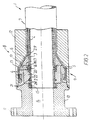
- Fig. 2 shows an assembly 8 of an end-fitting 9 and the flexible pressure pipe 1.
- the end-fitting 9 forms the transition between the pipe and the connector and for this purpose has a first part 10 with a connection flange 11, a second part 12 and a third part 29.
- the three parts 10; 12; 29 delimit a cavity 13 which partly is substantially cone-shaped.
- the end-fitting 9 has furthermore a through opening 14 for accommodating an end of the pipe 1.
- the flat metallic wires 6 of the tensile armour 5 are led into the cavity 13 in the end-fitting and a casting material, e.g. epoxy, is injected into the cavity making an anchoring for the wires.
- a casting material e.g. epoxy
- the carcass 2 is fastened to the end-fitting 9 by means of a lock nut 15, and to the inner lining 3 by means of a lock ring 16 fitting into an annular groove 17 in the wall of the through opening 14.
- the lock ring 16 is in the embodiment shown secured in the groove 17 by a casting material 18, e.g. epoxy, which is injected through a hole 19.
- a ring 20 provides a stop for the lock nut 15.
- a sealing ring 21 for tightening the end-fitting 9 and the inner lining 3 is fitted into a groove 22 in the ring 20.
- the carcass consists of helically wound metallic strips 23 forming a screwthread 24 with windings 25.
- the lock nut 15 simply is screwed on to the end of the carcass whereafter said end is inserted into the through opening 14 of the end-fitting 9, with the lock nut 15 placed in a annular holding groove 28 formed in the wall of the through opening.
- the lock nut 15 can also be embedded in a casting material (not shown), e.g. epoxy, for fixing the lock nut firmly in the holding groove of the end-fitting.
- a casting material e.g. epoxy
- the lock nut 15 is locked to the carcass 2 by screwing a screw 26 radially into the lock nut and into the carcass.
- this screw can be used for rotating the lock nut such that the windings 25 of the carcass 2 are tightened up.
- the surface of the lock nut 15 therefore has a coating 27 of a galvanic insulation material, e.g. PTFE, for preventing corrosion of the two parts which could be caused by such a potential.
- the insulating material may include solid insulation material for improving the pressure strength of the material.
- the lock nut is coated with the insulating material, but the lock nut can in another embodiment (not shown) consist totally of this material .
- the insulating material can also simply be in the form of annular discs (not shown) placed on each side of the lock nut.
Landscapes
- Engineering & Computer Science (AREA)
- General Engineering & Computer Science (AREA)
- Mechanical Engineering (AREA)
- Rigid Pipes And Flexible Pipes (AREA)
- Supports For Pipes And Cables (AREA)
- Joints Allowing Movement (AREA)
Abstract
Description
- The invention concerns an assembly of an end-fitting, having an axially extending through opening, with a flexible pressure pipe which is of a non-bonded structure comprising a number of layers including an inner carcass of an interlocking structure made from metallic strips forming a screw thread, the end part of which extends, in the assembled condition, into the through opening.
- Flexible pressure pipes are used in a variety of applications, including water supply lines, sewage lines and lines for transporting chemicals such as liquid ammonia and phosphoric acid and also high pressure offshore flexible pipes for the oil and gas industry.
- The joint between the carcass and the end-fitting must be able to resist the axial tensile load acting on the carcass, when the flexible pipe is descending over a great length. As the carcass is of an interlocking structure of a type which allows a mutual screwing movement of the windings of the metallic strips, the joint moreover must prevent the carcass from becoming unwound.
- Conventionally, such a joint is provided by screw shaped ribs which, during the extrusion of an inner lining of a plastic material around the carcass, are pressed into the grooves between the windings such that the carcass is secured by the lining which again is secured by the end-fitting. Owing to the notch sensitivity of the lining caused by this construction, the lining is, however, inclined to crack.
- This tendency is especially dangerous because temperature stresses can arise in the joint between the lining and the carcass, because the plastic material of the lining has a much higher coefficient of expansion than the material of the carcass which could be of e.g. stainless steel.
- The object of the invention is to provide an assembly of the type mentioned in the opening paragraph in which the joint between the carcass and the end-fitting is a simple and cheap structure and provides a greater resistance to axial tensile loads acting on the carcass and against unwinding of the carcass than has been known before.
- This is achieved in that the assembly comprises an annular holding groove which is formed in the wall of the through opening, and a lock nut which is screwed on the screwthread-formed strips of the end part of the carcass and fitted into the holding groove. In this construction the joint between the carcass and the end-fitting is independent of the inner lining which moreover can be made with optimal strength. When fixed in the holding groove, the lock nut also prevents the carcass from becoming unwound.
- By interposing a galvanic insulation material having a high electrical resistance between the lock nut and the end-fitting, an electric potential, which could cause galvanic corrosion, can be prevented from arising between said parts.
- The galvanic insulation material may advantageously be PTFE, preferably containing some solid insulation material for improving the pressure strength and the form stability of the material.
- In a simple and cheap embodiment, the galvanic insulation material can be in the form of an annular disc placed on each side of the lock nut. In a particularly expedient embodiment, the lock nut can also be coated with the galvanic insulation material or totally manufactured from it.
- The lock nut itself can be locked to the carcass by e.g. welding which, however, is time consuming and strenuous work and involves the risk that some of the plastic material of the pipe may be harmed by the heat generated by the welding process.
- The lock nut can, however, in a very simple way be locked to the carcass by screwing a screw radially into the lock nut and against the carcass. This screw can advantageously be used to rotate the lock nut and thereby tighten the carcass when the windings of this have been to some extent unwound.
- For fixing the lock nut firmly in the holding groove of the end-fitting, the lock nut can be embedded in a casting material, e.g. epoxy.
- The invention also concerns a method for assembling an end-fitting, having an axially extending through opening, with a flexible pressure pipe which is of a non-bonded structure comprising of a number of layers including an inner carcass of an interlocking structure made from metallic strips forming a screw thread, an end part of which extends, in assembled condition, into the through opening. The method comprises removing the layers surrounding the carcass at the end of the pipe, screwing a lock nut on the screwthread-form strips of the end part of the carcass, and placing the lock nut in a holding groove formed in the wall of the through opening. This method can be performed in a quick and time efficient manner in situ.
- The invention will be explained more fully by the following description, given by way of example, with reference to the drawings, in which:
- Fig. 1 shows, partly in axial section, a typical flexible pressure pipe,
- Fig. 2 shows, in axial section, an assembly of the flexible pressure pipe shown in fig. 1 and an end-fitting and
- Fig. 3 is a perspective view on an enlarged scale of a fragment of a lock nut mounted on an carcass of the flexible pipe shown in fig. 1.
-
- Fig. 1 shows a flexible pressure pipe, which is generally designated by 1. The pipe is of a non-bonded structure comprising a number of layers which in this embodiment are:
- a
carcass 2 of an interlocking structure made from metallic strips. The carcass serves, in the main, to prevent collapse of the pipe due to pipe decompression, external pressure, tensile armour pressure and mechanical crushing loads, - an
inner lining 3 in the form of an extruded polymer layer for providing internal fluid integrity, - a pressure armour 4 in the form of structural layers consisting of helically wound C-shaped metallic strips with a high lay angle,
- a
tensile armour 5 consisting of a pair of helically counter wound flatmetallic tensile wires 6 with a lay angle typically between 20° and 60°. The tensile armour serves to provide resistance to axial tensile loads, and - an
outer sheath 7 in the form of an extruded polymer for shielding the structural elements of the pipe from the outer environment and providing mechanical protection. - Fig. 2 shows an
assembly 8 of an end-fitting 9 and the flexible pressure pipe 1. The end-fitting 9 forms the transition between the pipe and the connector and for this purpose has afirst part 10 with a connection flange 11, asecond part 12 and athird part 29. The threeparts 10; 12; 29 delimit acavity 13 which partly is substantially cone-shaped. - The end-
fitting 9 has furthermore a through opening 14 for accommodating an end of the pipe 1. - When assembling the flexible pressure pipe 1 with the end-fitting 9 the flat
metallic wires 6 of thetensile armour 5 are led into thecavity 13 in the end-fitting and a casting material, e.g. epoxy, is injected into the cavity making an anchoring for the wires. - The
carcass 2 is fastened to the end-fitting 9 by means of alock nut 15, and to theinner lining 3 by means of alock ring 16 fitting into an annular groove 17 in the wall of the through opening 14. Thelock ring 16 is in the embodiment shown secured in the groove 17 by a casting material 18, e.g. epoxy, which is injected through ahole 19. - A
ring 20 provides a stop for thelock nut 15. In the embodiment shown asealing ring 21 for tightening the end-fitting 9 and theinner lining 3 is fitted into agroove 22 in thering 20. - As best seen in fig. 3 the carcass consists of helically wound
metallic strips 23 forming ascrewthread 24 withwindings 25. After having removed thelayers carcass 2 at the end of the pipe, thelock nut 15 simply is screwed on to the end of the carcass whereafter said end is inserted into the through opening 14 of the end-fitting 9, with thelock nut 15 placed in aannular holding groove 28 formed in the wall of the through opening. - For some applications the
lock nut 15 can also be embedded in a casting material (not shown), e.g. epoxy, for fixing the lock nut firmly in the holding groove of the end-fitting. - The
lock nut 15 is locked to thecarcass 2 by screwing ascrew 26 radially into the lock nut and into the carcass. When the carcass has been to some extent unwound, this screw can be used for rotating the lock nut such that thewindings 25 of thecarcass 2 are tightened up. - Between the lock nut and the end-fitting a galvanic potential could possibly arise. The surface of the
lock nut 15 therefore has acoating 27 of a galvanic insulation material, e.g. PTFE, for preventing corrosion of the two parts which could be caused by such a potential. The insulating material may include solid insulation material for improving the pressure strength of the material. - In the embodiment shown, the lock nut is coated with the insulating material, but the lock nut can in another embodiment (not shown) consist totally of this material .
- The insulating material can also simply be in the form of annular discs (not shown) placed on each side of the lock nut.
- Having thus provided a general discussion, and specific illustrations by way of examples, other embodiments are imaginable within the scope of the claims. The specific locking, according to the invention, between the
carcass 2 of the flexible pressure pipe 1 and the end-fitting 9 can be used in combination with other constructions of the joint between the end-fitting 9 and thetensile armour wires 6 and theinner lining 3, respectively, in addition to those described above and shown in the figures.
Claims (10)
- An assembly of an end-fitting (9), having an axially extending through opening (14), with a flexible pressure pipe (1) which is of a non-bonded structure comprising a number of layers (2,3,4,5,7) including an inner carcass (2) of an interlocking structure made from metallic strips (23) forming a screwthread, an end part of which extends, in assembled condition, into the through opening (14), characterized in that the assembly comprises an annular holding groove (28) which is formed in the wall of the through opening (14), and a lock nut (15) which is screwed on the screwthread-form strips of the end part of the carcass (2) and fitted into the holding groove (28).
- An assembly according to claim 1, characterized in that it further comprises a galvanic insulation material which is interposed between the lock nut (15) and the end-fitting (9).
- An assembly according to claim 2, characterized in that the galvanic insulation material is of a type having a high electrical resistance.
- An assembly according to claim 2 or claim 3, characterized in that the galvanic insulation material is PTFE.
- An assembly according to claim 2 or claim 3, characterized in that the galvanic insulation material is PTFE which is filled with solid insulation material.
- An assembly according to any of claims 2 - 5, characterized in that the galvanic insulation material is in the form of an annular disc, placed on each side of the lock nut (15).
- An assembly according to any of claims 2 - 5, characterized that the lock nut (15) is coated with or consists of the galvanic insulation material.
- An assembly according to any of claims 1 - 7, characterized in that it comprises at least one screw (26), which is screwed radially into the lock nut (15) and against the carcass (2).
- An assembly according to any of claims 1 - 8, characterized in that there is a gap between the lock nut (15) and the holding groove (28), and that this gap is filled with a casting material, e.g. a polymer such as epoxy.
- A method for assembling an end-fitting (9), having an axially extending through opening (14), with a flexible pressure pipe (1) which is of a non-bonded structure comprising a number of layers (3,4,5,7 including an inner carcass (2) of an interlocking structure made from metallic strips (23) forming a screwthread, an end part of which extends, in the assembled condition, into the through opening (14), characterized in that the method comprises,removing the layers (3,4,5,7) surrounding the carcass (2) at an end of the pipe (1),screwing a lock nut (15) on to the screwthread-form strips of the end part of the carcass (2), andplacing the lock nut (15) in a holding groove (28) formed in the wall of the through opening (14).
Applications Claiming Priority (1)
| Application Number | Priority Date | Filing Date | Title |
|---|---|---|---|
| PCT/DK1997/000452 WO1999019656A1 (en) | 1997-10-14 | 1997-10-14 | An assembly of a flexible pipe and an end-fitting |
Publications (2)
| Publication Number | Publication Date |
|---|---|
| EP1029193A1 EP1029193A1 (en) | 2000-08-23 |
| EP1029193B1 true EP1029193B1 (en) | 2002-09-18 |
Family
ID=8156303
Family Applications (1)
| Application Number | Title | Priority Date | Filing Date |
|---|---|---|---|
| EP97909207A Expired - Lifetime EP1029193B1 (en) | 1997-10-14 | 1997-10-14 | An assembly of a flexible pressure pipe and an end-fitting |
Country Status (7)
| Country | Link |
|---|---|
| US (1) | US6360781B1 (en) |
| EP (1) | EP1029193B1 (en) |
| AT (1) | ATE224516T1 (en) |
| AU (1) | AU4699297A (en) |
| CA (1) | CA2306497A1 (en) |
| DE (1) | DE69715689D1 (en) |
| WO (1) | WO1999019656A1 (en) |
Families Citing this family (34)
| Publication number | Priority date | Publication date | Assignee | Title |
|---|---|---|---|---|
| FR2816389B1 (en) * | 2000-11-08 | 2003-05-30 | Coflexip | FLEXIBLE CONDUIT TIP |
| DK200100832A (en) * | 2001-05-23 | 2001-05-23 | Nkt Flexibles Is | Method of manufacturing a reinforcing element for a flexible pipeline |
| WO2004001269A1 (en) * | 2002-06-20 | 2003-12-31 | Nkt Flexibles I/S | Flexible pipe structure connected to an end fitting comprising a self-sealing annular sealing gasket |
| US7303213B2 (en) * | 2002-11-29 | 2007-12-04 | Nkt Flexible I/S | Flexible pipe connected to an end fitting |
| EP1584388A1 (en) * | 2004-04-05 | 2005-10-12 | Kabushiki Kaisha Toyota Jidoshokki | Cap nut for envelopment casting, casting including the cap nut and method of enveloping the cap nut in casting |
| NO322237B1 (en) * | 2004-09-27 | 2006-09-04 | Aker Subsea As | Composite Pipe and Method for Manufacturing a Composite Pipe |
| JP3845868B1 (en) * | 2006-03-29 | 2006-11-15 | 東陶機器株式会社 | Water discharge device |
| FR2906595B1 (en) * | 2006-09-29 | 2010-09-17 | Technip France | FLEXIBLE TUBULAR FASTENING FIT WITH HIGH RESISTANCE |
| US20090160184A1 (en) * | 2007-12-20 | 2009-06-25 | Vo Dang The | End Connector For Flexible Pipe |
| US7946313B2 (en) | 2008-03-05 | 2011-05-24 | Vo Dang The | Flexible pipe |
| US8276620B2 (en) * | 2008-03-05 | 2012-10-02 | Vo Dang The | Flexible pipe for offshore and other applications |
| FR2928437B1 (en) * | 2008-03-07 | 2011-08-19 | Technip France | METHOD AND INSTALLATION FOR MOUNTING A CONNECTION BIT |
| FR2961577B1 (en) * | 2010-06-18 | 2013-05-10 | Technip France | CONNECTING TIP FOR A FLEXIBLE CONDUIT FOR TRANSPORTING A CRYOGENIC FLUID |
| HU229978B1 (en) * | 2011-10-18 | 2015-03-30 | Contitech Rubber Industrial Gumiipari Kft. | Rubber hose for high pressure gassy medium |
| FR2983937B1 (en) * | 2011-12-07 | 2014-08-29 | Technip France | CONNECTION TIP ASSEMBLY AND FLEXIBLE CONDUIT FOR TRANSPORTING A CRYOGENIC FLUID |
| FR2989144B1 (en) | 2012-04-04 | 2014-05-09 | Technip France | ASSEMBLY OF A FLEXIBLE TUBULAR CONDUIT FOR TRANSPORTING HYDROCARBON FLUIDS WITH A SECONDARY METAL TUBE |
| BR112014030179B1 (en) * | 2012-06-06 | 2020-11-17 | National Oilwell Varco Denmark I/S | riser tube to carry fluid between a superior installation and an underwater installation |
| BR112014032660B1 (en) | 2012-06-29 | 2020-10-27 | Equinor Energy As | tube housing to control upstream flow-induced vibration |
| US20150292663A1 (en) * | 2012-11-20 | 2015-10-15 | National Oilwell Varco Denmark I/S | An assembly of a flexible pipe and an end-fitting |
| GB201306823D0 (en) * | 2013-04-15 | 2013-05-29 | Wellstream Int Ltd | Flexible pipe components and method of manufacture of flexible pipe |
| US10088079B2 (en) | 2013-05-02 | 2018-10-02 | National Oilwell Varco Denmark I/S | Assembly of a flexible pipe and an end-fitting |
| CA2919122C (en) * | 2013-08-02 | 2021-06-15 | Kristian Glejbol | An unbonded flexible pipe and an offshore system comprising an unbonded flexible pipe |
| US20150145242A1 (en) * | 2013-11-25 | 2015-05-28 | Oceaneering International, Inc. | Alternatives to welding retention sleeves on steel tubes |
| US10655772B2 (en) | 2014-10-20 | 2020-05-19 | National Oilwell Varco Denmark I/S | Assembly comprising an end-fitting and an unbonded flexible pipe |
| GB201507720D0 (en) | 2015-05-06 | 2015-06-17 | Ge Oil And Gas Uk Ltd | Access provision |
| GB201507718D0 (en) * | 2015-05-06 | 2015-06-17 | Ge Oil And Gas Uk Ltd | Termination of a flexible pipe |
| CA2995257C (en) * | 2015-08-10 | 2023-08-22 | National Oilwell Varco Denmark I/S | An assembly comprising an end-fitting and an unbonded flexible pipe |
| FR3046210B1 (en) * | 2015-12-29 | 2018-02-02 | Technip France | FLEXIBLE LINE CONNECTION TIP, FLEXIBLE LINE AND ASSEMBLY METHOD THEREOF |
| FR3046452B1 (en) * | 2015-12-31 | 2018-02-16 | Technip France | CONNECTION TIP FOR A FLEXIBLE LINE, MEASURING DEVICE AND ASSOCIATED METHOD |
| AU2017219429B2 (en) * | 2016-02-15 | 2022-02-24 | National Oilwell Varco Denmark I/S | An assembly comprising an end-fitting for terminating an unbonded flexible pipe and an unbonded flexible pipe |
| EP3737884B1 (en) * | 2018-01-12 | 2023-11-08 | National Oilwell Varco Denmark I/S | An assembly of an end-fitting and an unbonded flexible pipe |
| WO2021102306A1 (en) | 2019-11-22 | 2021-05-27 | Trinity Bay Equipment Holdings, LLC | Swaged pipe fitting systems and methods |
| US11204114B2 (en) | 2019-11-22 | 2021-12-21 | Trinity Bay Equipment Holdings, LLC | Reusable pipe fitting systems and methods |
| BR112022010003A2 (en) | 2019-11-22 | 2022-08-16 | Trinity Bay Equipment Holdings Llc | SYSTEMS AND METHODS OF VESSEL TUBE FITTINGS |
Family Cites Families (16)
| Publication number | Priority date | Publication date | Assignee | Title |
|---|---|---|---|---|
| US816596A (en) * | 1905-06-08 | 1906-04-03 | Nicolas Perzoff | Coupling for internally and externally armored hose. |
| US910104A (en) * | 1906-07-31 | 1909-01-19 | Emil Witzenmann | Metallic hose. |
| US956077A (en) * | 1906-12-10 | 1910-04-26 | Edwin T Greenfield | Coupling. |
| US959187A (en) | 1909-11-30 | 1910-05-24 | Emil Witzenmann | End connection for metallic hose-pipes. |
| US984856A (en) * | 1910-05-21 | 1911-02-21 | Charles T Schoen | Flexible metallic tubing. |
| US2074425A (en) * | 1934-09-19 | 1937-03-23 | American Brass Co | Connection for flexible hose |
| FR863470A (en) | 1940-02-19 | 1941-04-02 | Fenwick S A | Fitting for flexible metal pipes |
| FR1094387A (en) | 1953-11-16 | 1955-05-20 | Conducto | Watertight fitting for flexible metal pipes and ducts |
| FR67525E (en) | 1955-02-03 | 1958-03-13 | Conducto | Watertight fitting for flexible metal pipes and ducts |
| DE1032987B (en) | 1956-04-25 | 1958-06-26 | Neue Argus Gmbh | Hose socket for a heavily loaded, reinforced rubber or plastic hose with a large diameter and method for attaching this socket to the hose |
| FR2207577A5 (en) | 1972-11-21 | 1974-06-14 | Inst Francais Du Petrole | |
| DE2541242A1 (en) * | 1975-09-12 | 1977-03-24 | Kabel Metallwerke Ghh | FITTING FOR A CORRUGATED PIPE |
| US4086665A (en) * | 1976-12-16 | 1978-05-02 | Thermo Electron Corporation | Artificial blood conduit |
| JPH0342302Y2 (en) * | 1987-11-10 | 1991-09-04 | ||
| US5845946A (en) * | 1996-09-11 | 1998-12-08 | Thomas; R. Winfield | Corrugated flexible hose coupling system |
| US6039083A (en) * | 1998-10-13 | 2000-03-21 | Wellstream, Inc. | Vented, layered-wall deepwater conduit and method |
-
1997
- 1997-10-14 US US09/529,593 patent/US6360781B1/en not_active Expired - Lifetime
- 1997-10-14 AT AT97909207T patent/ATE224516T1/en not_active IP Right Cessation
- 1997-10-14 WO PCT/DK1997/000452 patent/WO1999019656A1/en not_active Ceased
- 1997-10-14 DE DE69715689T patent/DE69715689D1/en not_active Expired - Lifetime
- 1997-10-14 AU AU46992/97A patent/AU4699297A/en not_active Abandoned
- 1997-10-14 CA CA002306497A patent/CA2306497A1/en not_active Abandoned
- 1997-10-14 EP EP97909207A patent/EP1029193B1/en not_active Expired - Lifetime
Also Published As
| Publication number | Publication date |
|---|---|
| US6360781B1 (en) | 2002-03-26 |
| AU4699297A (en) | 1999-05-03 |
| CA2306497A1 (en) | 1999-04-22 |
| ATE224516T1 (en) | 2002-10-15 |
| EP1029193A1 (en) | 2000-08-23 |
| WO1999019656A1 (en) | 1999-04-22 |
| DE69715689D1 (en) | 2002-10-24 |
Similar Documents
| Publication | Publication Date | Title |
|---|---|---|
| US6360781B1 (en) | Assembly of a flexible pipe and an end-fitting | |
| EP1023552B1 (en) | A flexible pipe with an associated end-fitting | |
| EP0978677B1 (en) | High-pressure fiber reinforced composite pipe joint | |
| KR102342659B1 (en) | A rigid joint assembly | |
| RU2358180C2 (en) | Threaded connection element and protective shell for it | |
| US20110162881A1 (en) | Well Seal for Electrical Wiring | |
| CN118564736B (en) | Steel wire embedded integrated full-drift-diameter acidizing and fracturing hose assembly and preparation method | |
| EP0580733A1 (en) | Double containment pipe joint assembly | |
| KR102151703B1 (en) | Polyethylene pipe structure for easy pipe detection line using conductive resin and electric wire | |
| KR200157905Y1 (en) | Spiral pipe and spiral pipe connecting structure | |
| WO1998037350A1 (en) | Pipe connection assembly | |
| CA2203643C (en) | High-pressure fiber reinforced composite pipe joint | |
| JPH07239068A (en) | Water leakage detection type flexible pipe joint | |
| RU2731980C2 (en) | Flexible pipe and flexible pipe end connection | |
| RU2160865C1 (en) | Insulating pipe coupling | |
| JP2024057902A (en) | Flanges | |
| GB2135137A (en) | Electrical cable glands and their manufacture | |
| KR20170084656A (en) | Encapsulated bolts of corrosion-resistant structure | |
| DK202200051A1 (en) | Method of curing a curable resin | |
| JPH1182839A (en) | Pipe fittings for corrugated pipes | |
| JP3345511B2 (en) | Pipe holder | |
| JPH0718096U (en) | Flexible fluid transport tube end structure | |
| CA2994879A1 (en) | Fastener having a flexible sleeve for connecting a coated conduit to a fitting | |
| JPH0254474B2 (en) | ||
| BR0316743B1 (en) | PIPE STRUCTURE |
Legal Events
| Date | Code | Title | Description |
|---|---|---|---|
| PUAI | Public reference made under article 153(3) epc to a published international application that has entered the european phase |
Free format text: ORIGINAL CODE: 0009012 |
|
| 17P | Request for examination filed |
Effective date: 20000515 |
|
| AK | Designated contracting states |
Kind code of ref document: A1 Designated state(s): AT BE CH DE DK ES FI FR GB GR IE IT LI LU MC NL PT SE |
|
| 17Q | First examination report despatched |
Effective date: 20010213 |
|
| GRAG | Despatch of communication of intention to grant |
Free format text: ORIGINAL CODE: EPIDOS AGRA |
|
| RTI1 | Title (correction) |
Free format text: AN ASSEMBLY OF A FLEXIBLE PRESSURE PIPE AND AN END-FITTING |
|
| GRAG | Despatch of communication of intention to grant |
Free format text: ORIGINAL CODE: EPIDOS AGRA |
|
| GRAH | Despatch of communication of intention to grant a patent |
Free format text: ORIGINAL CODE: EPIDOS IGRA |
|
| GRAH | Despatch of communication of intention to grant a patent |
Free format text: ORIGINAL CODE: EPIDOS IGRA |
|
| GRAA | (expected) grant |
Free format text: ORIGINAL CODE: 0009210 |
|
| AK | Designated contracting states |
Kind code of ref document: B1 Designated state(s): AT BE CH DE DK ES FI FR GB GR IE IT LI LU MC NL PT SE |
|
| PG25 | Lapsed in a contracting state [announced via postgrant information from national office to epo] |
Ref country code: LI Free format text: LAPSE BECAUSE OF FAILURE TO SUBMIT A TRANSLATION OF THE DESCRIPTION OR TO PAY THE FEE WITHIN THE PRESCRIBED TIME-LIMIT Effective date: 20020918 Ref country code: IT Free format text: LAPSE BECAUSE OF FAILURE TO SUBMIT A TRANSLATION OF THE DESCRIPTION OR TO PAY THE FEE WITHIN THE PRESCRIBED TIME-LIMIT;WARNING: LAPSES OF ITALIAN PATENTS WITH EFFECTIVE DATE BEFORE 2007 MAY HAVE OCCURRED AT ANY TIME BEFORE 2007. THE CORRECT EFFECTIVE DATE MAY BE DIFFERENT FROM THE ONE RECORDED. Effective date: 20020918 Ref country code: GR Free format text: LAPSE BECAUSE OF FAILURE TO SUBMIT A TRANSLATION OF THE DESCRIPTION OR TO PAY THE FEE WITHIN THE PRESCRIBED TIME-LIMIT Effective date: 20020918 Ref country code: FI Free format text: LAPSE BECAUSE OF FAILURE TO SUBMIT A TRANSLATION OF THE DESCRIPTION OR TO PAY THE FEE WITHIN THE PRESCRIBED TIME-LIMIT Effective date: 20020918 Ref country code: CH Free format text: LAPSE BECAUSE OF FAILURE TO SUBMIT A TRANSLATION OF THE DESCRIPTION OR TO PAY THE FEE WITHIN THE PRESCRIBED TIME-LIMIT Effective date: 20020918 Ref country code: BE Free format text: LAPSE BECAUSE OF FAILURE TO SUBMIT A TRANSLATION OF THE DESCRIPTION OR TO PAY THE FEE WITHIN THE PRESCRIBED TIME-LIMIT Effective date: 20020918 Ref country code: AT Free format text: LAPSE BECAUSE OF FAILURE TO SUBMIT A TRANSLATION OF THE DESCRIPTION OR TO PAY THE FEE WITHIN THE PRESCRIBED TIME-LIMIT Effective date: 20020918 |
|
| REF | Corresponds to: |
Ref document number: 224516 Country of ref document: AT Date of ref document: 20021015 Kind code of ref document: T |
|
| REG | Reference to a national code |
Ref country code: GB Ref legal event code: FG4D |
|
| REG | Reference to a national code |
Ref country code: CH Ref legal event code: EP |
|
| PG25 | Lapsed in a contracting state [announced via postgrant information from national office to epo] |
Ref country code: LU Free format text: LAPSE BECAUSE OF NON-PAYMENT OF DUE FEES Effective date: 20021014 Ref country code: IE Free format text: LAPSE BECAUSE OF NON-PAYMENT OF DUE FEES Effective date: 20021014 |
|
| REG | Reference to a national code |
Ref country code: IE Ref legal event code: FG4D |
|
| REF | Corresponds to: |
Ref document number: 69715689 Country of ref document: DE Date of ref document: 20021024 |
|
| PG25 | Lapsed in a contracting state [announced via postgrant information from national office to epo] |
Ref country code: SE Free format text: LAPSE BECAUSE OF FAILURE TO SUBMIT A TRANSLATION OF THE DESCRIPTION OR TO PAY THE FEE WITHIN THE PRESCRIBED TIME-LIMIT Effective date: 20021218 Ref country code: DK Free format text: LAPSE BECAUSE OF FAILURE TO SUBMIT A TRANSLATION OF THE DESCRIPTION OR TO PAY THE FEE WITHIN THE PRESCRIBED TIME-LIMIT Effective date: 20021218 |
|
| PG25 | Lapsed in a contracting state [announced via postgrant information from national office to epo] |
Ref country code: PT Free format text: LAPSE BECAUSE OF FAILURE TO SUBMIT A TRANSLATION OF THE DESCRIPTION OR TO PAY THE FEE WITHIN THE PRESCRIBED TIME-LIMIT Effective date: 20021219 Ref country code: DE Free format text: LAPSE BECAUSE OF FAILURE TO SUBMIT A TRANSLATION OF THE DESCRIPTION OR TO PAY THE FEE WITHIN THE PRESCRIBED TIME-LIMIT Effective date: 20021219 |
|
| ET | Fr: translation filed | ||
| PG25 | Lapsed in a contracting state [announced via postgrant information from national office to epo] |
Ref country code: ES Free format text: LAPSE BECAUSE OF FAILURE TO SUBMIT A TRANSLATION OF THE DESCRIPTION OR TO PAY THE FEE WITHIN THE PRESCRIBED TIME-LIMIT Effective date: 20030328 |
|
| REG | Reference to a national code |
Ref country code: CH Ref legal event code: PL |
|
| PG25 | Lapsed in a contracting state [announced via postgrant information from national office to epo] |
Ref country code: MC Free format text: LAPSE BECAUSE OF NON-PAYMENT OF DUE FEES Effective date: 20030501 |
|
| PLBE | No opposition filed within time limit |
Free format text: ORIGINAL CODE: 0009261 |
|
| STAA | Information on the status of an ep patent application or granted ep patent |
Free format text: STATUS: NO OPPOSITION FILED WITHIN TIME LIMIT |
|
| REG | Reference to a national code |
Ref country code: IE Ref legal event code: MM4A |
|
| 26N | No opposition filed |
Effective date: 20030619 |
|
| PGFP | Annual fee paid to national office [announced via postgrant information from national office to epo] |
Ref country code: NL Payment date: 20030919 Year of fee payment: 7 |
|
| PG25 | Lapsed in a contracting state [announced via postgrant information from national office to epo] |
Ref country code: NL Free format text: LAPSE BECAUSE OF NON-PAYMENT OF DUE FEES Effective date: 20050501 |
|
| NLV4 | Nl: lapsed or anulled due to non-payment of the annual fee |
Effective date: 20050501 |
|
| REG | Reference to a national code |
Ref country code: FR Ref legal event code: CD Owner name: NATIONAL OILWELL VARCO DENMARK I/S, DK Effective date: 20120926 Ref country code: FR Ref legal event code: CA Effective date: 20120926 |
|
| PGFP | Annual fee paid to national office [announced via postgrant information from national office to epo] |
Ref country code: GB Payment date: 20141022 Year of fee payment: 18 Ref country code: FR Payment date: 20141031 Year of fee payment: 18 |
|
| GBPC | Gb: european patent ceased through non-payment of renewal fee |
Effective date: 20151014 |
|
| PG25 | Lapsed in a contracting state [announced via postgrant information from national office to epo] |
Ref country code: GB Free format text: LAPSE BECAUSE OF NON-PAYMENT OF DUE FEES Effective date: 20151014 |
|
| REG | Reference to a national code |
Ref country code: FR Ref legal event code: ST Effective date: 20160630 |
|
| PG25 | Lapsed in a contracting state [announced via postgrant information from national office to epo] |
Ref country code: FR Free format text: LAPSE BECAUSE OF NON-PAYMENT OF DUE FEES Effective date: 20151102 |