EP1029140B1 - Structural components of swimming pools - Google Patents
Structural components of swimming pools Download PDFInfo
- Publication number
- EP1029140B1 EP1029140B1 EP98947195A EP98947195A EP1029140B1 EP 1029140 B1 EP1029140 B1 EP 1029140B1 EP 98947195 A EP98947195 A EP 98947195A EP 98947195 A EP98947195 A EP 98947195A EP 1029140 B1 EP1029140 B1 EP 1029140B1
- Authority
- EP
- European Patent Office
- Prior art keywords
- rim
- base plate
- wall
- section
- opening
- Prior art date
- Legal status (The legal status is an assumption and is not a legal conclusion. Google has not performed a legal analysis and makes no representation as to the accuracy of the status listed.)
- Expired - Lifetime
Links
- 230000009182 swimming Effects 0.000 title claims abstract description 15
- 229910052751 metal Inorganic materials 0.000 claims description 4
- 239000002184 metal Substances 0.000 claims description 4
- 239000007769 metal material Substances 0.000 claims description 3
- 230000009977 dual effect Effects 0.000 abstract description 5
- 238000009434 installation Methods 0.000 description 5
- XLYOFNOQVPJJNP-UHFFFAOYSA-N water Substances O XLYOFNOQVPJJNP-UHFFFAOYSA-N 0.000 description 5
- 230000007246 mechanism Effects 0.000 description 4
- 238000009432 framing Methods 0.000 description 3
- 238000010276 construction Methods 0.000 description 2
- 239000000463 material Substances 0.000 description 2
- 239000013589 supplement Substances 0.000 description 2
- 230000006978 adaptation Effects 0.000 description 1
- 229910052782 aluminium Inorganic materials 0.000 description 1
- XAGFODPZIPBFFR-UHFFFAOYSA-N aluminium Chemical compound [Al] XAGFODPZIPBFFR-UHFFFAOYSA-N 0.000 description 1
- 230000015572 biosynthetic process Effects 0.000 description 1
- 230000008859 change Effects 0.000 description 1
- 230000007423 decrease Effects 0.000 description 1
- 230000003247 decreasing effect Effects 0.000 description 1
- 230000014759 maintenance of location Effects 0.000 description 1
- 230000004048 modification Effects 0.000 description 1
- 238000012986 modification Methods 0.000 description 1
- 239000002994 raw material Substances 0.000 description 1
- 238000007493 shaping process Methods 0.000 description 1
Images


Classifications
-
- E—FIXED CONSTRUCTIONS
- E04—BUILDING
- E04H—BUILDINGS OR LIKE STRUCTURES FOR PARTICULAR PURPOSES; SWIMMING OR SPLASH BATHS OR POOLS; MASTS; FENCING; TENTS OR CANOPIES, IN GENERAL
- E04H4/00—Swimming or splash baths or pools
- E04H4/0018—Easily movable or transportable swimming pools
Definitions
- This invention relates to structural components of swimming pools, and more particularly to framing members or supports of above-ground swimming pools as recited in the preamble part of claim 1.
- U.S. Patent No. 4,182,087 to Schall, et al. describes and illustrates an exemplary above-ground, essentially oval swimming pool.
- the pool is designed to be built "without the necessity of a large top and bottom rail and, theoretically, without a top and bottom rail at all.”
- construction of the pool allows use of a lower guide rail "solely for the purpose of shaping" the pool.
- the guide rail can be removed after pool wall construction is completed or need not be used in the first place in the event that the shape of the outer pool wall has already been marked out.
- the guide rail is not subject to forces caused by water as it fills the pool and accordingly has a simple, unslotted "L"-shaped cross section.
- No base plate is utilized in pools constructed according to the disclosure of the Schall, et al. patent.
- U.S. Patent No. 3,745,593 to Wall details an above-ground swimming pool in which flat base plates and "bottom rail members" are employed. Described therein is the structure of a bottom rail member, which includes a web portion having a pair of spaced apart vertical flanges integrally formed therewith and projecting upwardly therefrom. One of the vertical flanges has an inturned flange integrally formed therewith which terminates in a terminal flange. The other vertical flange projects upwardly beyond the inturned flange. (Numerals omitted.) Defined between the inner vertical flange and the inturned flange is a slot, in which is received the lower edge of a continuous side wall preferably formed of corrugated sheet metal. No mechanism for guiding the sheet metal appears provided by the bottom rail member, however, and no positive locking means is furnished as part of the rail member itself.
- the structure of a base plate included as a part of a vertical leg support of the completed pool Intended to be substantially flat, the base plate nonetheless has an upturned inner flange terminating in an inwardly curved upper end. A portion of the inner flange "is also struck inwardly to define a locking element . . . which is adapted to coact with the bottom rails for releasably locking the rails to the base plate.”
- Spaced vertical guide elements of the base plate purportedly define guide ways for pairs of bottom rail members, with the inwardly curved upper end of the inner flange overlying the inner vertical flange of each bottom rail.
- the "inwardly struck locking element" of the base plate also “serves as a stop to limit inward movement of each pair of bottom rail members which are interconnected with each base plate.” Again, however, no positive interlocking mechanism with the bottom rail members is provided, and the base plate lacks any slot for supporting a received upright or vertical leg.
- US patent N° 4,062,158 relates to a swimming pool arrangement in which lugs extends upward from a surface of a base plate.
- the present invention provides a rim and base plate adapted for positive interlock.
- each rim of the invention is a slot in its bottom surface in which a corresponding upstanding tab of a base plate is received.
- the rim additionally incorporates two parallel flanged sections which collectively form an elongated slot into which a side wall is fitted.
- the dual flanges help increase the support provided to the side wall against the outward water pressure of the pool, while their differing heights assist in guiding the side wall into the slot during installation. Decreasing the height of one flange set additionally requires less raw material to be used in its formation.
- base plates of the invention may include a generally semi-circular slot, formed by vertical surfaces of (typically but not necessarily) differing heights, for receiving an upright and frictionally retaining it in position. Dual tabs protruding within the plate permit its receipt of two sections of rim. Through this interlock mechanism each plate thus effectively "connects" two rim sections as the pool is installed.
- base plates of the present invention additionally provide greater guidance for the rims than do existing plates.
- those of the present invention may at their edges supply guidance surfaces adjacent not only the bottom of the rim, but adjacent both sides and most of the top as well.
- the guide elements of the base plate of the Wall patent for example, are centrally located and thus initially provide no guidance for the rim as it starts to slide inward from the edge of the plate during installation.
- embodiments of the present base plate furnish such guidance at its edges.
- These base plates further may be designed to provide enhanced support to the bottoms of the side walls and contain holes through which any water contacting them may drain.
- FIGS. 1-4 illustrate a portion of a rim 10 of the present invention.
- Rim 10 includes first section 14 and second section 18, which are connected by bottom 22.
- Rim 10 is typically made of metal, although other materials may be used instead if necessary or desired.
- Rim 10 additionally often is curved to enable its use in connection with oval, circular, and other non-rectangular swimming pools.
- first section 14 comprises a substantially vertical wall 26 and a downturned flange 30 connected by a substantially horizontal face 34.
- Second section 18 is similarly configured, with substantially vertical wall 38 and downturned flange 42 connected by substantially horizontal face 46.
- Each of walls 26 and 38 and flanges 30 and 42 is (more or less) parallel to the others, with flanges 30 and 42 forming elongated slot 50 into which a side wall of a swimming pool may be fitted.
- Flanges 30 and 42 furthermore, effectively provide opposed surfaces for guiding the side wall into position and retaining it there against the outward water pressure of the pool. Because the height H 1 of wall 38 is significantly less than the height H 2 of wall 26, it helps prevent the side wall from "catching" on face 46 during installation; instead, the side wall is able, typically, to slide downward along flange 30 until captured within slot 50.
- FIG. 3 details bottom 22 of rim 10.
- Bottom 22 is, generally, a flat surface, thereby assisting in levelling rim 10 (and the swimming pool) vis-a-vis the ground or other surface on which it is installed.
- opening 54 is included, however, in segments of rim 10 in segments of rim 10 in segments of rim 10 in segments of rim 10 in segments of rim 10 in segments of rim 10 in segments of rim 10 in segments of rim 10 .
- opening 54 functions as part of an interlock system for the framing of the swimming pool.
- FIGS. 5-9 show an exemplary base plate 58 (or aspects thereof) of the present invention.
- Base plate 58 includes bottom 62, which usually is flat, and from which integrally-formed (dual) walls 66 and 70 upwardly protrude.
- walls 66 and 70 are, in substantial part, semicircular, while terminating in respective straight segments 66A and 70A.
- Collectively walls 66 and 70 thus define a slot 74 into which a vertical support, or "upright” may be fitted, the cross-sectional shape of the upright matching that of the slot 74.
- walls 66 and 70 need not be substantially semicircular, but rather may assume shapes similar to those of the uprights.
- walls 66 and 70 of base plate 58 have different heights, facilitating installation of the upright in a manner similar to that of the side wall of the pool.
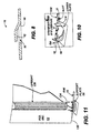
- each tab 78 (FIG. 8) is integrally formed with bottom 62, with a generally horizontal section 82 being connected to bottom 62 by an angled section 86. Section 82 is designed to fit within and be received by opening 54, thereby forming part of the previously-mentioned interlock system for framing a swimming pool.
- guide wall 90 which assists in receiving and appropriately positioning a rim 10 within base plate 58. Together with bottom 62 and edge 94 of wall 70, guide wall 90 defines three-quarters of an opening 98A of base plate 58 into which rim 10 may be fitted. Lip 102 (integrally formed with guide wall 90) and overhang 106 of wall 70 define the remainder of opening 98A, with edges of lip 102 and overhang 106 being spaced approximately (or slightly larger than) the width of slot 50. The distance between lip 102 and bottom 62 is approximately (or slightly larger than) H 1 , while that between overhang 106 and bottom 62 is approximately (or slightly larger than) H 2 .
- opening 98A preferably is slightly wider than bottom 22 of the rim 10. Opening 98A nonetheless is approximately the cross-sectional shape and size of rim 10, however, providing substantial guidance as the rim 10 is inserted through it.
- a second opening 98B likewise is present in base plate 58 for receiving another section of rim 10.
- FIG. 9 is the built-up status of wall 70.
- undulating supplement 110 which functions as a flange for or other strengthener of the base plate 58.
- supplement 110 helps prevent wall 70 from breaking based on the outward water pressure presented to the upright from within the pool.
- base plates 58 are positioned atop blocks buried in the ground. Optimal results are achieved for some uses of base plates 58 when they are placed atop buried blocks whose upper surfaces are flush with the ground. In other words, bottom 62 of base plate 58 usually is level with the ground on which the swimming pool is being installed, effectively providing a footing for an upright of the pool.
- End 118 of rim 10 initially is passed through opening 98A (oriented so that face 34 is underneath overhang 106 and face 46 is underneath lip 102), so that bottom 22 of rim 10 depresses tab 78A.
- opening 98A As additional portions of rim 10 pass through opening 98A, opening 54 ultimately passes over tab 78A, whose section 82 springs into and is thus received by opening 54, effectively locking rim 10 in place relative to base plate 58.
- another section of rim 10 may be passed through opening 98B until its opening 54 receives section 82 of tab 78B.
- side wall 122 and upright 126 may be installed.
- the lower edge 130 of side wall 122 fits within slot 50 defined by the sections of rim 10, while lower edge 134 of upright 126 fits within slot 74 of base plate 58.
- neither side wall 122 nor upright 126 need be bolted or otherwise fastened to rim 10 or base plate 58, although any suitable fastening system may be employed to enhance the footing provided by these components when necessary or desired.
Landscapes
- Engineering & Computer Science (AREA)
- Architecture (AREA)
- Civil Engineering (AREA)
- Structural Engineering (AREA)
- Toys (AREA)
- Joining Of Building Structures In Genera (AREA)
- Cosmetics (AREA)
- Bridges Or Land Bridges (AREA)
Abstract
Description
can be removed after pool wall construction is completed or need not be used in the first place in the event that the shape of the outer pool wall has already been marked out.
Because temporary, the guide rail is not subject to forces caused by water as it fills the pool and accordingly has a simple, unslotted "L"-shaped cross section. No base plate, furthermore, is utilized in pools constructed according to the disclosure of the Schall, et al. patent.
includes a web portion having a pair of spaced apart vertical flanges integrally formed therewith and projecting upwardly therefrom. One of the vertical flanges has an inturned flange integrally formed therewith which terminates in a terminal flange. The other vertical flange projects upwardly beyond the inturned flange.
(Numerals omitted.) Defined between the inner vertical flange and the inturned flange is a slot, in which is received the lower edge of a continuous side wall preferably formed of corrugated sheet metal. No mechanism for guiding the sheet metal appears provided by the bottom rail member, however, and no positive locking means is furnished as part of the rail member itself.
Claims (6)
- A footing for a swimming pool having a side wall (122) and an upright (126) comprising:characterized in that the base plate further comprises a tab (78) integrally formed with and extending upward from the bottom and the rim further comprises a bottom (22) defining an opening (54) for receiving the tab.a base plate (58) comprising a bottom (62) and first and second walls (66, 70) extending upward from the bottom and defining a slot (74) for receiving the upright; anda rim (10) comprising first and second sections (14, 18) defining a slot (50) for receiving the side wall;
- A footing according to claim 1, characterized in that each of the first and second walls of the base plate has a component of semi-circular shape.
- A footing according to claim 1, characterized in that the tab comprises:a. a substantially horizontal section (82) adapted to be received by the opening in the bottom of the rim; andb. an angled section (86) connecting the substantially horizontal section to the bottom of the base plate.
- A footing according to claim 1, characterized in that:a. the first wall of the base plate defines an overhang;b. the base plate further comprises a guide wall (90) extending upward from the bottom and terminating in a lip (102); andc. the overhang, bottom, guide wall, and lip define an opening in the base plate through which the rim is adapted to pass.
- A footing according to claim 1, characterized in that the base plate is made of non-metallic material and the rim is made of metal.
- A footing according to claim 1, characterized in that:a. the first section of the rim comprises:i. a substantially vertical wall (26) connected to the bottom and of selected height H;ii. a downturned flange (30); andiii. a substantially horizontal face (34) connecting the substantially vertical wall and downturned flange; andb. the second section of the rim comprises:i. a substantially vertical wall (38) connected to the bottom and of height less than H;ii. a downturned flange (42); andiii. a substantially horizontal face (46) connecting the substantially vertical wall and downturned flange.
Applications Claiming Priority (3)
| Application Number | Priority Date | Filing Date | Title |
|---|---|---|---|
| US946798 | 1997-10-08 | ||
| US08/946,798 US5907875A (en) | 1997-10-08 | 1997-10-08 | Structural components of swimming pools |
| PCT/US1998/019762 WO1999018306A1 (en) | 1997-10-08 | 1998-09-22 | Structural components of swimming pools |
Publications (2)
| Publication Number | Publication Date |
|---|---|
| EP1029140A1 EP1029140A1 (en) | 2000-08-23 |
| EP1029140B1 true EP1029140B1 (en) | 2003-05-21 |
Family
ID=25485003
Family Applications (1)
| Application Number | Title | Priority Date | Filing Date |
|---|---|---|---|
| EP98947195A Expired - Lifetime EP1029140B1 (en) | 1997-10-08 | 1998-09-22 | Structural components of swimming pools |
Country Status (6)
| Country | Link |
|---|---|
| US (1) | US5907875A (en) |
| EP (1) | EP1029140B1 (en) |
| AT (1) | ATE241073T1 (en) |
| DE (1) | DE69814902D1 (en) |
| ES (1) | ES2199464T3 (en) |
| WO (1) | WO1999018306A1 (en) |
Families Citing this family (1)
| Publication number | Priority date | Publication date | Assignee | Title |
|---|---|---|---|---|
| US6272696B1 (en) * | 2000-09-25 | 2001-08-14 | Wil-Bar International, Inc. | Hinged top rail for above-ground pool and method of pool assembly using same |
Family Cites Families (11)
| Publication number | Priority date | Publication date | Assignee | Title |
|---|---|---|---|---|
| US1853090A (en) * | 1929-01-19 | 1932-04-12 | Globe Wernicke Co | Partition and post construction |
| US3225362A (en) * | 1963-08-13 | 1965-12-28 | Muskin Mfg Co Inc | Sectional above ground swimming pool construction |
| US3233251A (en) * | 1964-01-15 | 1966-02-08 | Muskin Mfg Company Inc | Pool structure |
| US3268917A (en) * | 1965-09-03 | 1966-08-30 | Coleco Ind Inc | Swimming pool frame assembly |
| US3280408A (en) * | 1965-10-23 | 1966-10-25 | Coleco Ind Inc | Water-retaining recreational structure for swimming pools and the like |
| US3562822A (en) * | 1969-03-07 | 1971-02-16 | Doughboy Ind Inc | Swimming pool with lock-on rails |
| US3745593A (en) * | 1971-09-23 | 1973-07-17 | Doughboy Ind Inc | Multi-piece vertical support for swimming pools |
| US3877085A (en) * | 1974-04-08 | 1975-04-15 | Delta Ind Inc | Above-ground modular swimming pool enclosures |
| US4062158A (en) * | 1976-07-12 | 1977-12-13 | Swim 'n Play, Inc. | Prefabricated swimming pool construction |
| US4182087A (en) * | 1978-04-24 | 1980-01-08 | Esther Williams Swimming Pools | Swimming pool |
| US4413361A (en) * | 1980-11-10 | 1983-11-08 | Doughboy Recreational, Inc. | Deck and fence structure for above ground swimming pools |
-
1997
- 1997-10-08 US US08/946,798 patent/US5907875A/en not_active Expired - Fee Related
-
1998
- 1998-09-22 WO PCT/US1998/019762 patent/WO1999018306A1/en not_active Ceased
- 1998-09-22 EP EP98947195A patent/EP1029140B1/en not_active Expired - Lifetime
- 1998-09-22 DE DE69814902T patent/DE69814902D1/en not_active Expired - Lifetime
- 1998-09-22 ES ES98947195T patent/ES2199464T3/en not_active Expired - Lifetime
- 1998-09-22 AT AT98947195T patent/ATE241073T1/en not_active IP Right Cessation
Also Published As
| Publication number | Publication date |
|---|---|
| EP1029140A1 (en) | 2000-08-23 |
| DE69814902D1 (en) | 2003-06-26 |
| ATE241073T1 (en) | 2003-06-15 |
| WO1999018306A1 (en) | 1999-04-15 |
| ES2199464T3 (en) | 2004-02-16 |
| US5907875A (en) | 1999-06-01 |
Similar Documents
| Publication | Publication Date | Title |
|---|---|---|
| US4065883A (en) | Water conducting members spaced between spaced exposed building support beams | |
| US4630966A (en) | Drainage channel | |
| US4845908A (en) | Composite metal/concrete floor and method | |
| US3233251A (en) | Pool structure | |
| EP0634535B1 (en) | Planar roofing made of folded metal sheets | |
| JP3040174B2 (en) | Swimming pool wall structure | |
| CA2409312C (en) | Ballast block deck system and pedestal assembly therefor | |
| US3862532A (en) | Roof tile | |
| US3416165A (en) | Swimming pool construction | |
| US4759159A (en) | Building panel joint | |
| US5291714A (en) | Grating assembly | |
| US4741134A (en) | Composite metal/concrete bar joist floor and method | |
| US4413361A (en) | Deck and fence structure for above ground swimming pools | |
| US5702204A (en) | Apparatus for connecting and aligning frame member sections of a trench | |
| JPH0251007B2 (en) | ||
| US4023217A (en) | Swimming pool construction | |
| US5732521A (en) | Longitudinal or transverse support for ceiling panelling | |
| EP0879925B1 (en) | Support system for vessels such as swimming pools | |
| US5907875A (en) | Structural components of swimming pools | |
| AU602108B2 (en) | Forming keyed joints in concrete | |
| US20110099934A1 (en) | Underdeck ceiling and collector system | |
| GB2094847A (en) | A drainage trap | |
| GB2110266A (en) | Sheet metal facade units | |
| US4370839A (en) | Pool construction | |
| US12296204B1 (en) | Device for fixing rope for building cleaning |
Legal Events
| Date | Code | Title | Description |
|---|---|---|---|
| PUAI | Public reference made under article 153(3) epc to a published international application that has entered the european phase |
Free format text: ORIGINAL CODE: 0009012 |
|
| 17P | Request for examination filed |
Effective date: 20000425 |
|
| AK | Designated contracting states |
Kind code of ref document: A1 Designated state(s): AT DE ES FR GB IT |
|
| 17Q | First examination report despatched |
Effective date: 20020225 |
|
| GRAH | Despatch of communication of intention to grant a patent |
Free format text: ORIGINAL CODE: EPIDOS IGRA |
|
| GRAH | Despatch of communication of intention to grant a patent |
Free format text: ORIGINAL CODE: EPIDOS IGRA |
|
| GRAA | (expected) grant |
Free format text: ORIGINAL CODE: 0009210 |
|
| AK | Designated contracting states |
Designated state(s): AT DE ES FR GB IT |
|
| PG25 | Lapsed in a contracting state [announced via postgrant information from national office to epo] |
Ref country code: IT Free format text: LAPSE BECAUSE OF FAILURE TO SUBMIT A TRANSLATION OF THE DESCRIPTION OR TO PAY THE FEE WITHIN THE PRE;WARNING: LAPSES OF ITALIAN PATENTS WITH EFFECTIVE DATE BEFORE 2007 MAY HAVE OCCURRED AT ANY TIME BEFORE 2007. THE CORRECT EFFECTIVE DATE MAY BE DIFFERENT FROM THE ONE RECORDED.SCRIBED TIME-LIMIT Effective date: 20030521 Ref country code: AT Free format text: LAPSE BECAUSE OF FAILURE TO SUBMIT A TRANSLATION OF THE DESCRIPTION OR TO PAY THE FEE WITHIN THE PRESCRIBED TIME-LIMIT Effective date: 20030521 |
|
| REG | Reference to a national code |
Ref country code: GB Ref legal event code: FG4D |
|
| REF | Corresponds to: |
Ref document number: 69814902 Country of ref document: DE Date of ref document: 20030626 Kind code of ref document: P |
|
| PG25 | Lapsed in a contracting state [announced via postgrant information from national office to epo] |
Ref country code: DE Free format text: LAPSE BECAUSE OF FAILURE TO SUBMIT A TRANSLATION OF THE DESCRIPTION OR TO PAY THE FEE WITHIN THE PRESCRIBED TIME-LIMIT Effective date: 20030822 |
|
| PG25 | Lapsed in a contracting state [announced via postgrant information from national office to epo] |
Ref country code: GB Free format text: LAPSE BECAUSE OF NON-PAYMENT OF DUE FEES Effective date: 20030922 |
|
| REG | Reference to a national code |
Ref country code: FR Ref legal event code: CD |
|
| REG | Reference to a national code |
Ref country code: ES Ref legal event code: FG2A Ref document number: 2199464 Country of ref document: ES Kind code of ref document: T3 |
|
| REG | Reference to a national code |
Ref country code: ES Ref legal event code: PC2A |
|
| ET | Fr: translation filed | ||
| PLBE | No opposition filed within time limit |
Free format text: ORIGINAL CODE: 0009261 |
|
| STAA | Information on the status of an ep patent application or granted ep patent |
Free format text: STATUS: NO OPPOSITION FILED WITHIN TIME LIMIT |
|
| RAP2 | Party data changed (patent owner data changed or rights of a patent transferred) |
Owner name: ZODIAC AMERICAN POOLS INC. |
|
| 26N | No opposition filed |
Effective date: 20040224 |
|
| GBPC | Gb: european patent ceased through non-payment of renewal fee |
Effective date: 20030922 |
|
| PGFP | Annual fee paid to national office [announced via postgrant information from national office to epo] |
Ref country code: FR Payment date: 20040920 Year of fee payment: 7 |
|
| PGFP | Annual fee paid to national office [announced via postgrant information from national office to epo] |
Ref country code: ES Payment date: 20041008 Year of fee payment: 7 |
|
| PG25 | Lapsed in a contracting state [announced via postgrant information from national office to epo] |
Ref country code: ES Free format text: LAPSE BECAUSE OF NON-PAYMENT OF DUE FEES Effective date: 20050923 |
|
| PG25 | Lapsed in a contracting state [announced via postgrant information from national office to epo] |
Ref country code: FR Free format text: LAPSE BECAUSE OF NON-PAYMENT OF DUE FEES Effective date: 20060531 |
|
| REG | Reference to a national code |
Ref country code: FR Ref legal event code: ST Effective date: 20060531 |
|
| REG | Reference to a national code |
Ref country code: ES Ref legal event code: FD2A Effective date: 20050923 |