EP1028502A2 - Smart laser with automated beam quality control - Google Patents
Smart laser with automated beam quality control Download PDFInfo
- Publication number
- EP1028502A2 EP1028502A2 EP00102800A EP00102800A EP1028502A2 EP 1028502 A2 EP1028502 A2 EP 1028502A2 EP 00102800 A EP00102800 A EP 00102800A EP 00102800 A EP00102800 A EP 00102800A EP 1028502 A2 EP1028502 A2 EP 1028502A2
- Authority
- EP
- European Patent Office
- Prior art keywords
- laser
- positioner
- chamber
- smart
- computer controller
- Prior art date
- Legal status (The legal status is an assumption and is not a legal conclusion. Google has not performed a legal analysis and makes no representation as to the accuracy of the status listed.)
- Granted
Links
- 238000003908 quality control method Methods 0.000 title 1
- 230000003287 optical effect Effects 0.000 claims description 4
- 230000006835 compression Effects 0.000 description 11
- 238000007906 compression Methods 0.000 description 11
- 238000000034 method Methods 0.000 description 9
- 238000005452 bending Methods 0.000 description 8
- 230000000694 effects Effects 0.000 description 5
- 238000001459 lithography Methods 0.000 description 5
- 238000010420 art technique Methods 0.000 description 2
- 238000005259 measurement Methods 0.000 description 2
- 238000005457 optimization Methods 0.000 description 2
- 229910001374 Invar Inorganic materials 0.000 description 1
- 230000002457 bidirectional effect Effects 0.000 description 1
- 238000004590 computer program Methods 0.000 description 1
- 230000006866 deterioration Effects 0.000 description 1
- 238000010586 diagram Methods 0.000 description 1
- 238000004519 manufacturing process Methods 0.000 description 1
- 230000000737 periodic effect Effects 0.000 description 1
Images




Classifications
-
- G—PHYSICS
- G03—PHOTOGRAPHY; CINEMATOGRAPHY; ANALOGOUS TECHNIQUES USING WAVES OTHER THAN OPTICAL WAVES; ELECTROGRAPHY; HOLOGRAPHY
- G03F—PHOTOMECHANICAL PRODUCTION OF TEXTURED OR PATTERNED SURFACES, e.g. FOR PRINTING, FOR PROCESSING OF SEMICONDUCTOR DEVICES; MATERIALS THEREFOR; ORIGINALS THEREFOR; APPARATUS SPECIALLY ADAPTED THEREFOR
- G03F7/00—Photomechanical, e.g. photolithographic, production of textured or patterned surfaces, e.g. printing surfaces; Materials therefor, e.g. comprising photoresists; Apparatus specially adapted therefor
- G03F7/70—Microphotolithographic exposure; Apparatus therefor
- G03F7/70008—Production of exposure light, i.e. light sources
- G03F7/70025—Production of exposure light, i.e. light sources by lasers
-
- H—ELECTRICITY
- H01—ELECTRIC ELEMENTS
- H01S—DEVICES USING THE PROCESS OF LIGHT AMPLIFICATION BY STIMULATED EMISSION OF RADIATION [LASER] TO AMPLIFY OR GENERATE LIGHT; DEVICES USING STIMULATED EMISSION OF ELECTROMAGNETIC RADIATION IN WAVE RANGES OTHER THAN OPTICAL
- H01S3/00—Lasers, i.e. devices using stimulated emission of electromagnetic radiation in the infrared, visible or ultraviolet wave range
- H01S3/05—Construction or shape of optical resonators; Accommodation of active medium therein; Shape of active medium
- H01S3/08—Construction or shape of optical resonators or components thereof
-
- G—PHYSICS
- G02—OPTICS
- G02B—OPTICAL ELEMENTS, SYSTEMS OR APPARATUS
- G02B5/00—Optical elements other than lenses
- G02B5/18—Diffraction gratings
- G02B5/1828—Diffraction gratings having means for producing variable diffraction
-
- G—PHYSICS
- G03—PHOTOGRAPHY; CINEMATOGRAPHY; ANALOGOUS TECHNIQUES USING WAVES OTHER THAN OPTICAL WAVES; ELECTROGRAPHY; HOLOGRAPHY
- G03F—PHOTOMECHANICAL PRODUCTION OF TEXTURED OR PATTERNED SURFACES, e.g. FOR PRINTING, FOR PROCESSING OF SEMICONDUCTOR DEVICES; MATERIALS THEREFOR; ORIGINALS THEREFOR; APPARATUS SPECIALLY ADAPTED THEREFOR
- G03F7/00—Photomechanical, e.g. photolithographic, production of textured or patterned surfaces, e.g. printing surfaces; Materials therefor, e.g. comprising photoresists; Apparatus specially adapted therefor
- G03F7/70—Microphotolithographic exposure; Apparatus therefor
- G03F7/70483—Information management; Active and passive control; Testing; Wafer monitoring, e.g. pattern monitoring
-
- G—PHYSICS
- G03—PHOTOGRAPHY; CINEMATOGRAPHY; ANALOGOUS TECHNIQUES USING WAVES OTHER THAN OPTICAL WAVES; ELECTROGRAPHY; HOLOGRAPHY
- G03F—PHOTOMECHANICAL PRODUCTION OF TEXTURED OR PATTERNED SURFACES, e.g. FOR PRINTING, FOR PROCESSING OF SEMICONDUCTOR DEVICES; MATERIALS THEREFOR; ORIGINALS THEREFOR; APPARATUS SPECIALLY ADAPTED THEREFOR
- G03F7/00—Photomechanical, e.g. photolithographic, production of textured or patterned surfaces, e.g. printing surfaces; Materials therefor, e.g. comprising photoresists; Apparatus specially adapted therefor
- G03F7/70—Microphotolithographic exposure; Apparatus therefor
- G03F7/70483—Information management; Active and passive control; Testing; Wafer monitoring, e.g. pattern monitoring
- G03F7/7055—Exposure light control in all parts of the microlithographic apparatus, e.g. pulse length control or light interruption
- G03F7/70575—Wavelength control, e.g. control of bandwidth, multiple wavelength, selection of wavelength or matching of optical components to wavelength
-
- H—ELECTRICITY
- H01—ELECTRIC ELEMENTS
- H01S—DEVICES USING THE PROCESS OF LIGHT AMPLIFICATION BY STIMULATED EMISSION OF RADIATION [LASER] TO AMPLIFY OR GENERATE LIGHT; DEVICES USING STIMULATED EMISSION OF ELECTROMAGNETIC RADIATION IN WAVE RANGES OTHER THAN OPTICAL
- H01S3/00—Lasers, i.e. devices using stimulated emission of electromagnetic radiation in the infrared, visible or ultraviolet wave range
- H01S3/05—Construction or shape of optical resonators; Accommodation of active medium therein; Shape of active medium
- H01S3/08—Construction or shape of optical resonators or components thereof
- H01S3/08081—Unstable resonators
-
- H—ELECTRICITY
- H01—ELECTRIC ELEMENTS
- H01S—DEVICES USING THE PROCESS OF LIGHT AMPLIFICATION BY STIMULATED EMISSION OF RADIATION [LASER] TO AMPLIFY OR GENERATE LIGHT; DEVICES USING STIMULATED EMISSION OF ELECTROMAGNETIC RADIATION IN WAVE RANGES OTHER THAN OPTICAL
- H01S3/00—Lasers, i.e. devices using stimulated emission of electromagnetic radiation in the infrared, visible or ultraviolet wave range
- H01S3/10—Controlling the intensity, frequency, phase, polarisation or direction of the emitted radiation, e.g. switching, gating, modulating or demodulating
- H01S3/105—Controlling the intensity, frequency, phase, polarisation or direction of the emitted radiation, e.g. switching, gating, modulating or demodulating by controlling the mutual position or the reflecting properties of the reflectors of the cavity, e.g. by controlling the cavity length
- H01S3/1055—Controlling the intensity, frequency, phase, polarisation or direction of the emitted radiation, e.g. switching, gating, modulating or demodulating by controlling the mutual position or the reflecting properties of the reflectors of the cavity, e.g. by controlling the cavity length one of the reflectors being constituted by a diffraction grating
-
- H—ELECTRICITY
- H01—ELECTRIC ELEMENTS
- H01S—DEVICES USING THE PROCESS OF LIGHT AMPLIFICATION BY STIMULATED EMISSION OF RADIATION [LASER] TO AMPLIFY OR GENERATE LIGHT; DEVICES USING STIMULATED EMISSION OF ELECTROMAGNETIC RADIATION IN WAVE RANGES OTHER THAN OPTICAL
- H01S3/00—Lasers, i.e. devices using stimulated emission of electromagnetic radiation in the infrared, visible or ultraviolet wave range
- H01S3/10—Controlling the intensity, frequency, phase, polarisation or direction of the emitted radiation, e.g. switching, gating, modulating or demodulating
- H01S3/13—Stabilisation of laser output parameters, e.g. frequency or amplitude
-
- H—ELECTRICITY
- H01—ELECTRIC ELEMENTS
- H01S—DEVICES USING THE PROCESS OF LIGHT AMPLIFICATION BY STIMULATED EMISSION OF RADIATION [LASER] TO AMPLIFY OR GENERATE LIGHT; DEVICES USING STIMULATED EMISSION OF ELECTROMAGNETIC RADIATION IN WAVE RANGES OTHER THAN OPTICAL
- H01S3/00—Lasers, i.e. devices using stimulated emission of electromagnetic radiation in the infrared, visible or ultraviolet wave range
- H01S3/14—Lasers, i.e. devices using stimulated emission of electromagnetic radiation in the infrared, visible or ultraviolet wave range characterised by the material used as the active medium
- H01S3/22—Gases
- H01S3/223—Gases the active gas being polyatomic, i.e. containing two or more atoms
- H01S3/225—Gases the active gas being polyatomic, i.e. containing two or more atoms comprising an excimer or exciplex
-
- H—ELECTRICITY
- H01—ELECTRIC ELEMENTS
- H01S—DEVICES USING THE PROCESS OF LIGHT AMPLIFICATION BY STIMULATED EMISSION OF RADIATION [LASER] TO AMPLIFY OR GENERATE LIGHT; DEVICES USING STIMULATED EMISSION OF ELECTROMAGNETIC RADIATION IN WAVE RANGES OTHER THAN OPTICAL
- H01S3/00—Lasers, i.e. devices using stimulated emission of electromagnetic radiation in the infrared, visible or ultraviolet wave range
- H01S3/05—Construction or shape of optical resonators; Accommodation of active medium therein; Shape of active medium
- H01S3/08—Construction or shape of optical resonators or components thereof
- H01S3/08004—Construction or shape of optical resonators or components thereof incorporating a dispersive element, e.g. a prism for wavelength selection
- H01S3/08009—Construction or shape of optical resonators or components thereof incorporating a dispersive element, e.g. a prism for wavelength selection using a diffraction grating
-
- H—ELECTRICITY
- H01—ELECTRIC ELEMENTS
- H01S—DEVICES USING THE PROCESS OF LIGHT AMPLIFICATION BY STIMULATED EMISSION OF RADIATION [LASER] TO AMPLIFY OR GENERATE LIGHT; DEVICES USING STIMULATED EMISSION OF ELECTROMAGNETIC RADIATION IN WAVE RANGES OTHER THAN OPTICAL
- H01S3/00—Lasers, i.e. devices using stimulated emission of electromagnetic radiation in the infrared, visible or ultraviolet wave range
- H01S3/10—Controlling the intensity, frequency, phase, polarisation or direction of the emitted radiation, e.g. switching, gating, modulating or demodulating
- H01S3/13—Stabilisation of laser output parameters, e.g. frequency or amplitude
- H01S3/131—Stabilisation of laser output parameters, e.g. frequency or amplitude by controlling the active medium, e.g. by controlling the processes or apparatus for excitation
- H01S3/134—Stabilisation of laser output parameters, e.g. frequency or amplitude by controlling the active medium, e.g. by controlling the processes or apparatus for excitation in gas lasers
-
- H—ELECTRICITY
- H01—ELECTRIC ELEMENTS
- H01S—DEVICES USING THE PROCESS OF LIGHT AMPLIFICATION BY STIMULATED EMISSION OF RADIATION [LASER] TO AMPLIFY OR GENERATE LIGHT; DEVICES USING STIMULATED EMISSION OF ELECTROMAGNETIC RADIATION IN WAVE RANGES OTHER THAN OPTICAL
- H01S3/00—Lasers, i.e. devices using stimulated emission of electromagnetic radiation in the infrared, visible or ultraviolet wave range
- H01S3/10—Controlling the intensity, frequency, phase, polarisation or direction of the emitted radiation, e.g. switching, gating, modulating or demodulating
- H01S3/13—Stabilisation of laser output parameters, e.g. frequency or amplitude
- H01S3/139—Stabilisation of laser output parameters, e.g. frequency or amplitude by controlling the mutual position or the reflecting properties of the reflectors of the cavity, e.g. by controlling the cavity length
- H01S3/1392—Stabilisation of laser output parameters, e.g. frequency or amplitude by controlling the mutual position or the reflecting properties of the reflectors of the cavity, e.g. by controlling the cavity length by using a passive reference, e.g. absorption cell
Definitions
- control of beam cross section intensity values are important.
- FIG. 1 shows some of the features of a prior art KrF excimer laser system used for IC lithography.
- the system includes a laser frame structure 5 within which is mounted a laser chamber 3 containing two elongated electrodes (not shown) between which is a gain medium, a line narrowing module (referred to as a "line narrowing package” or LNP) 7 shown disproportionately large and an output coupler 4.
- LNP line narrowing package
- the LNP portion of FIG. 1 represents a top view of the LNP.
- the beam cross section is generally rectangular, typically about 3.5 mm wide and about 15 mm high.
- each of the line narrowing module 7 and the output coupler module 4 comprise frames which are fixedly mourned to laser frame structure 5.
- Optical components within the frames of the output coupler module and the line narrowing module are adjusted manually to define the laser resonance cavity.
- the chamber is adjustably mounted within the laser frame so that it can be finely positioned manually within the defined resonance cavity from time to time in the direction of the beam width as shown by arrows 3A on FIG. 1. These adjustments permit a laser technician to align the resonance cavity with the gain medium in order to achieve optimum beam output parameters.
- a three prism beam expander 18 is comprised of prisms 8, 10 and 12 mounted on prism plate 13.
- prism plate 13 can be manually adjusted in the direction of arrows 13A as an alignment technique.
- the prior art device also includes a manual adjustment of the curvature of the surface of grating 16 into an increasingly or decreasingly concave shape by expanding or contracting bending mechanism 20 to place larger or smaller compressive forces on legs 17A and 17B.
- the adjustment is done primarily to control bandwidth of the output beam.
- Another prior art technique for forcing a concave shape on the grating surface is described in U.S. Patent No. 5,095,492.
- Pulse energy is controlled in a feedback system by measuring the output pulse energy with a beam output monitor 22 as shown in FIG. 1 and then using these measurements with a computer controller 24 to control the high voltage applied between the electrodes in order to regulate pulse energy within desired limits.
- the beam output monitor 22 also called a wavemeter
- Computer controller 24 adjusts the pivot position of tuning mirror 14 using stepper motor 15 in order to control the nominal wavelength of the beam to within desired limits.
- the present invention provides a smart laser having automatic computer control of pulse energy, wavelength and bandwidth using feedback signals from a wavemeter.
- Pulse energy is controlled by controlling discharge voltage, wavelength by controlling the position of an R MAX mirror in a line narrowing module and bandwidth is controller by adjusting the curvature of a grating in the line narrowing module.
- Preferred embodiments include automatic feedback control of horizontal and vertical beam profile by automatic adjustment of a prism plate on which beam expander prisms are located and automatic adjustment of the R MAX tilt.
- Other preferred embodiments include automatic adjustment of the horizontal position of the laser chamber within the resonance cavity.
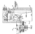
- FIG. 2 A combination block diagram schematic drawing of a first preferred embodiment of the present invention is shown in FIG. 2.
- This drawing shows important improvements over the prior art which automate the alignment of the laser chamber and components in order to provide greatly improved instant control of the important laser beam parameters.
- the new laser frame 5A has added on to it a chamber position stepper motor to automatically adjust the horizontal position of the chamber in the direction 3A.
- the new LNP 7A includes a prism plate stepper motor 32, an R-max tilt stepper motor 34 and a grating curvature motor 30. All of these stepper motors are controlled by computer controller 24A.
- a grating curvature stepper motor 30 has been added to control the curvature of grating 16.
- the system includes a new bending mechanism design 20A which has the capacity to apply either a compressive force to spread apart legs 17A and 17B to create a concave curvature in the lined surface of grating 16 or a tension force to pull together legs 17A and 17B to create a convex curvature in the lined surface of grating 16.
- Control of motor 30 is provided by computer controller 24.
- FIG. 3A shows a grating assembly having a bidirectional control unit attached to it but with no bending force applied to the grating. Shown are grating 16, left end plate 17B, right end plate 17A, compression spring housing 48, left compression spring 50, right compression spring 51, adjustment shaft 44 and piston 49 which is fixedly pinned to adjustment shaft 44.
- Adjustment shaft 44 comprises threaded length 44A (1/4-28 UNF-2B x 1.38 long) which mates with threaded channel in right end plate 17A.
- both springs are applying equal compressive force which offset each other or both springs may be unloaded.
- the curvature of the grating surface is adjusted by turning shaft 44.
- left compression spring 50 is compressed against the left side of housing 48 and piston 49 as shown by the two arrows inside housing 48 in FIG. 3B.
- the compression force pushes rod 44 to the right and housing 48 to the left which has the effect of pushing apart the two end plates 17A and 17B as shown by arrows 56. This has the effect of bending the surface of grating 1 into a concave shape as shown by line 58.
- rod 44 has 28 threads per inch and the springs are rated at 52 pounds per inch. Operators are able with this design to make extremely fine adjustments to the curvature of the grating surface.
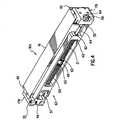
- FIG. 4 is a perspective view of a grating assembly 16A fabricated by Applicants and their co-workers.
- the assembly is comprised of grating 16, two grating end plates 42 (bonded to grating 16) right bi-directional bandwidth control end plate 17A, lock nut 56, invar base plate 53 bonded to grating 16, alignment rod 44, socket 64, two liner bearings 62, compression spring housing 48, right compression spring 51, two thrust bearings 63, piston 49 pinned to rod 44, left compression spring 50, travel limiting piston 57 pinned to rod 44, radial ball bearing 54, pivot shall 55 and left bandwidth control end plate 17B.
- FIG. 5 is a cutaway drawing of LNP 7A. It shows the two-way curvature-controlled grating assembly 16A. Also shown is grating curvature control stepper motor 30 for controlling the curvature of the lined surface of grating 16 from concave to convex as explained above with reference to FIGS. 3A, 3B and 3C. FIG. 5 also shows prism plate adjustment motor 32. Motor controls for R MAX mirror 14 are not shown in FIG. 5.
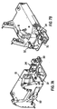
- FIG. 7A Bottom views of line narrowing package 7A are shown in FIG. 7A (from the front, i.e., looking from the laser toward the LNP) and in FIG. 7B (from the rear).
- Grating curvature stepper motor 30 is shown mounted on its mounting plate.
- Prism plate motor is shown at 32 and R MAX tilt motor is shown at 34 and R MAX stepper motor is shown at 15.
- the beam entrance-exit port for the LNP is shown at 60.
- Position control of prism plate 13 is depicted in cutaway drawing 5A which also shows prism plate stepper motor 32.
- Stepper motor 32 is also shown in FIGS. 7A and 7B mounted on its mounting plate. Control of motor 32 is provided by computer controller 24.
- R MAX tilt control stepper motor is shown at 34 in FIGS. 7A and 7B and 6A, C and D.
- the tilt of R MAX mirror 14 is provided by R MAX stepper motor 34 which is also controlled by computer controller 24.
- the tilt of mirror 14 determines the vertical angle of light reflecting in the resonance cavity.
- wavelength selection is provided with stepper motor 15 setting the pivotal horizontal position of tuning mirror 14 based on direction from computer controller 24 which utilizes feedback wavelength information from wavemeter 22 in accordance with prior art techniques as discussed in the background section of this specification.
- This first preferred embodiment include chamber position stepper motor 36 shown in FIG. 2 which automatically adjusts relative to frame 5 (on which is mounted output coupler 4 and line narrowing package 7) the horizontal position of laser chamber 3 (and thus the horizontal position of the gain medium contained therein) in the direction perpendicular to the direction of beam 6.
- Computer controller is preferably programmed with control algorithms which control motors 36, 32, 34, 30 in addition to 15 in order to maintain beam parameters within desired ranges based on feedback signals from wavemeter 22.
- a simple approach is to hold all positions constant except one (for example chamber position stepper motor) and scan that item over a predetermined range to seek the position producing the optimum beam performance looking at parameters such as pulse energy output, pulse energy stability and bandwidth.
- the computer can be programmed to make these scans on operator instruction or to do the scans on a predetermined periodic basis.
- the computer could also be programmed to make one or more of these types of scans, seeking optimum position, if wavemeter detects a deterioration of any beam quality.
- beam parameters are known to vary as a function of pulse number (i.e., time after the start of the bursts).
- the computer controller could be programmed to adjust one or more of the stepper motors as a function of time after the start of the bursts.
- a figure of merit M is defined in order to judge optimum laser performance. Adjustments are then made to maximize the value of the figure of merit. This value is computed using input from sensors which measure the beam in real time. These sensors typically provide values such as energy stability, laser efficiency (energy out for voltage in), bandwidth, beam width, beam symmetry, pointing stability, etc. In general the best figure of merit will combine the several parameters which are most important for determining success in the application, such as lithography exposure. For example if only laser efficiency as measured by pulse energy/charging voltage (E) was considered important to the figure of merit would be
- M E - (W SH )(SH) - (W SV )(SV) - (W B )(B) - (W WS )(WS) - (W DS )(DS)
- the computer is programmed to make adjustments to the stepper positions, measure E, SH, SV, B, WS and DS, apply weighting factors to achieve minimum figures of merit M.
- the downhill simplex method is a reliable technique, however, if very rapid convergence is needed other well known techniques could be utilized.
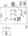
- Applicants provided the optical setup described in FIG. 8.
- An image of the laser beam at the output coupler aperture was relayed optically through lens 70 to a fluorescent screen and beam parameters including vertical and horizontal symmetry were determined utilizing a CCD camera focused on fluorescent screen 74 as shown in FIG. 8.
- the fluorescent screen converts the UV light from the laser to visible light which is monitored by the CCD camera.
- the analog output from the camera is converted to digital with a video frame grabber and the output of the frame grabber is analyzed by a computer processor.
- lens 72 focuses the laser beam onto the fluorescent screen 74 and is located so that perfectly colluminated light entering the lens would appear as a diffraction limited spot at the fluorescent screen. Therefore, the size of the spot is a measure of the divergence of the beam and movement of the spot is a measure of changes in beam pointing.
- each of the stepper motors could be replaced with alternative positioner units such as, ac or dc motors or hydraulic or pneumatic positioners. Many methods of controlling the positioners other than the suggested computer programs could be utilized.
- One or more stepper motors could be applied to the output coupler to automatically position it using similar techniques as described above for the R MAX mirror.
- Three strong permanent magnets could be used in the place of the two compression springs with one of the magnets replacing the piston as shown in FIG. 6. Magnet 60 is fixed to rod 4 and magnets 62 and 64 are fixed to housing 8. Rod 4 passes through holes in magnets 62 and 64.
- the effect of screwing rod 4 into and out of housing 8 is substantially the same as described above.
- the curvature of the grating could be accomplished using any of a large number of techniques. For example, compression or tension could be applied at a number of points to create virtually any shape desired and these shapes could be subject to feedback computer control.
- the tuning mirror 14 could be a deformable mirror subject to deformation to any desired shape in order to correct wave front distortions. The deformation could be manual or it could be piezoelectric or motor controlled and as with the grating it could be controlled in a feedback circuit. The invention is therefore to be limited only as indicated by the scope of the appended claims and their legal equivalents.
Landscapes
- Physics & Mathematics (AREA)
- Electromagnetism (AREA)
- Optics & Photonics (AREA)
- Engineering & Computer Science (AREA)
- Plasma & Fusion (AREA)
- General Physics & Mathematics (AREA)
- Lasers (AREA)
- Exposure Of Semiconductors, Excluding Electron Or Ion Beam Exposure (AREA)
- Exposure And Positioning Against Photoresist Photosensitive Materials (AREA)
- Laser Beam Processing (AREA)
Abstract
Description
Claims (13)
- A smart narrow band electric discharge laser for producing an output laser beam said laser comprising:A) a laser from;B) a laser chamber adjustably mounted in said frame;C) a laser gas contained within said chamber;D) two elongated spaced apart electrodes contained within said chamber, said electrodes and laser gas between them defining a gain medium;E) an output coupler;F) a line narrowing module comprising a prism beam expander, an RMAX mirror and a bendable grating defining a grating curvature, said line narrowing module and its optical components and the output coupler defining a resonance cavity;G) a wavemeter for detecting laser beam parameters including at least pulse energy, wavelength and bandwidth;H) a computer controller; andI) a grating curvature positioner controlled by said computer controller to adjust the grating curvature based on bandwidth information provided to said computer controller by said wavemeter.
- A smart laser as in Claim 1 and further comprising a chamber positioner unit for positioning said chamber in a horizontal direction so that said gain medium is in a desired position with respect t the resonance cavity.
- A smart laser as in Claim 2 wherein the computer controller is programmed to control said chamber positioner unit to position said chamber based on feedback information from said wavemeter.
- A smart laser as in Claim 1 wherein said prism beam expander comprises a plurality of prisms disposed on a prism plate, and further comprising a prism plate positioner unit for positioning said prism plate.
- A smart laser as in Claim 4 wherein said computer controller is programmed to control said prism plate positioner unit to position said prism plate based on feedback information from said wavemeter.
- A smart laser as in Claim 1 and further comprising an RMAX tilt positioner to tilt said RMAX mirror to control vertical spatial parameters of said output laser beam.
- A smart laser as in Claim 6 wherein said computer controller is programmed to control said tilt positioner to tilt said RMAX mirror based on beam information from said wavemeter.
- A smart laser as in Claim 1 wherein said beam expander comprises a plurality of prisms disposed on a movable prism plate and further comprising:A) a chamber positioner unit for positioning said chamber in a horizontal direction upon control signals from said computer controller;B) a prism plate positioning unit for positioning said prism plate upon control signals from said computer controller;C) an RMAX tilt positioner to tilt said RMAX mirror based upon control signals from said computer controller; andD) an RMAX pivot positioner to pivot said RMAX mirror to adjust nominal wavelength of said output beam based on control signals from said computer controller.
- A smart laser as in Claim 1 wherein said grating curvature positioner comprises a stepper motor.
- A smart laser as in Claim 2 wherein said chamber positioner is a stepper motor.
- A smart laser as in Claim 4 wherein said prism plate positioner is a stepper motor.
- A smart laser as in Claim 6 wherein said RMAX tilt positioner is a stepper motor.
- A smart laser as in Claim 8 wherein all of said positioners are stepper motors.
Applications Claiming Priority (4)
| Application Number | Priority Date | Filing Date | Title |
|---|---|---|---|
| US09/248,466 US6094448A (en) | 1997-07-01 | 1999-02-11 | Grating assembly with bi-directional bandwidth control |
| US248466 | 1999-02-11 | ||
| US09/390,579 US6212217B1 (en) | 1997-07-01 | 1999-09-03 | Smart laser with automated beam quality control |
| US390579 | 1999-09-03 |
Publications (3)
| Publication Number | Publication Date |
|---|---|
| EP1028502A2 true EP1028502A2 (en) | 2000-08-16 |
| EP1028502A3 EP1028502A3 (en) | 2003-08-27 |
| EP1028502B1 EP1028502B1 (en) | 2007-10-24 |
Family
ID=26939374
Family Applications (1)
| Application Number | Title | Priority Date | Filing Date |
|---|---|---|---|
| EP00102800A Expired - Lifetime EP1028502B1 (en) | 1999-02-11 | 2000-02-10 | Laser with automated beam quality control |
Country Status (7)
| Country | Link |
|---|---|
| US (1) | US6212217B1 (en) |
| EP (1) | EP1028502B1 (en) |
| JP (1) | JP3837005B2 (en) |
| KR (1) | KR100329958B1 (en) |
| AT (1) | ATE376710T1 (en) |
| DE (1) | DE60036828T2 (en) |
| TW (1) | TW447182B (en) |
Cited By (2)
| Publication number | Priority date | Publication date | Assignee | Title |
|---|---|---|---|---|
| EP1330859A4 (en) * | 2000-10-31 | 2005-04-13 | Cymer Inc | Smart laser with fast deformable grating |
| CN107968305A (en) * | 2017-11-23 | 2018-04-27 | 黑龙江工程学院 | A kind of four ends pump narrow spaces Solid State Laser generating means |
Families Citing this family (26)
| Publication number | Priority date | Publication date | Assignee | Title |
|---|---|---|---|---|
| US20020127497A1 (en) * | 1998-09-10 | 2002-09-12 | Brown Daniel J. W. | Large diffraction grating for gas discharge laser |
| JP2000208848A (en) * | 1999-01-19 | 2000-07-28 | Komatsu Ltd | Fixing device for bending mechanism of reflective wavelength selective element |
| JP2000205966A (en) * | 1999-01-20 | 2000-07-28 | Komatsu Ltd | Vacuum ultraviolet laser wavelength measuring device |
| US6700915B2 (en) | 1999-03-12 | 2004-03-02 | Lambda Physik Ag | Narrow band excimer laser with a resonator containing an optical element for making wavefront corrections |
| US6298080B1 (en) | 1999-03-12 | 2001-10-02 | Lambda Physik Ag | Narrow band excimer or molecular fluorine laser with adjustable bandwidth |
| US6865210B2 (en) * | 2001-05-03 | 2005-03-08 | Cymer, Inc. | Timing control for two-chamber gas discharge laser system |
| US6882674B2 (en) * | 1999-12-27 | 2005-04-19 | Cymer, Inc. | Four KHz gas discharge laser system |
| US6496528B2 (en) * | 1999-09-03 | 2002-12-17 | Cymer, Inc. | Line narrowing unit with flexural grating mount |
| EP1240694B1 (en) * | 1999-12-22 | 2006-11-22 | Cymer, Inc. | Line narrowed laser with bidirection beam expansion |
| JP3357341B2 (en) * | 2000-05-19 | 2002-12-16 | 知夫 藤岡 | Cylindrical straight slab type gas laser |
| US6603789B1 (en) | 2000-07-05 | 2003-08-05 | Lambda Physik Ag | Narrow band excimer or molecular fluorine laser with improved beam parameters |
| US6801561B2 (en) | 2000-09-25 | 2004-10-05 | Lambda Physik Ag | Laser system and method for spectral narrowing through wavefront correction |
| US6856638B2 (en) * | 2000-10-23 | 2005-02-15 | Lambda Physik Ag | Resonator arrangement for bandwidth control |
| US6839372B2 (en) * | 2000-11-17 | 2005-01-04 | Cymer, Inc. | Gas discharge ultraviolet laser with enclosed beam path with added oxidizer |
| US20050286599A1 (en) * | 2004-06-29 | 2005-12-29 | Rafac Robert J | Method and apparatus for gas discharge laser output light coherency reduction |
| US7643522B2 (en) * | 2004-11-30 | 2010-01-05 | Cymer, Inc. | Method and apparatus for gas discharge laser bandwidth and center wavelength control |
| US20060114956A1 (en) * | 2004-11-30 | 2006-06-01 | Sandstrom Richard L | High power high pulse repetition rate gas discharge laser system bandwidth management |
| US7366219B2 (en) * | 2004-11-30 | 2008-04-29 | Cymer, Inc. | Line narrowing module |
| JP4911558B2 (en) | 2005-06-29 | 2012-04-04 | 株式会社小松製作所 | Narrow band laser equipment |
| US8379687B2 (en) | 2005-06-30 | 2013-02-19 | Cymer, Inc. | Gas discharge laser line narrowing module |
| US7321607B2 (en) * | 2005-11-01 | 2008-01-22 | Cymer, Inc. | External optics and chamber support system |
| US8259764B2 (en) | 2006-06-21 | 2012-09-04 | Cymer, Inc. | Bandwidth control device |
| US8144739B2 (en) * | 2008-10-24 | 2012-03-27 | Cymer, Inc. | System method and apparatus for selecting and controlling light source bandwidth |
| GB0920752D0 (en) * | 2009-11-26 | 2010-01-13 | Univ St Andrews | Laser |
| CN115395349B (en) * | 2022-10-27 | 2023-02-03 | 中国航天三江集团有限公司 | Large-aperture laser system and light beam quality diagnosis method thereof |
| CN121307604B (en) * | 2025-12-11 | 2026-02-13 | 山东省科学院激光研究所 | Narrow bandwidth fiber laser system and control method thereof |
Family Cites Families (8)
| Publication number | Priority date | Publication date | Assignee | Title |
|---|---|---|---|---|
| US5025445A (en) * | 1989-11-22 | 1991-06-18 | Cymer Laser Technologies | System for, and method of, regulating the wavelength of a light beam |
| US5095492A (en) | 1990-07-17 | 1992-03-10 | Cymer Laser Technologies | Spectral narrowing technique |
| US5230005A (en) * | 1991-11-05 | 1993-07-20 | The United States Of America As Represented By The Secretary Of The Navy | Electronic tuning of a broadband laser |
| JP3397337B2 (en) * | 1992-04-02 | 2003-04-14 | 株式会社小松製作所 | Narrow band laser device |
| US5297155A (en) * | 1993-03-29 | 1994-03-22 | E-Tek Dynamics, Inc. | Tunable laser assembly |
| US5856991A (en) * | 1997-06-04 | 1999-01-05 | Cymer, Inc. | Very narrow band laser |
| EP0992092B1 (en) * | 1997-07-01 | 2003-04-23 | Cymer, Inc. | Very narrow band laser with unstable resonance cavity |
| US6055348A (en) * | 1998-09-23 | 2000-04-25 | Lucent Technologies Inc. | Tunable grating device and optical communication devices and systems comprising same |
-
1999
- 1999-09-03 US US09/390,579 patent/US6212217B1/en not_active Expired - Lifetime
-
2000
- 2000-02-10 EP EP00102800A patent/EP1028502B1/en not_active Expired - Lifetime
- 2000-02-10 DE DE60036828T patent/DE60036828T2/en not_active Expired - Lifetime
- 2000-02-10 KR KR1020000006210A patent/KR100329958B1/en not_active Expired - Fee Related
- 2000-02-10 AT AT00102800T patent/ATE376710T1/en not_active IP Right Cessation
- 2000-02-14 JP JP2000077242A patent/JP3837005B2/en not_active Expired - Lifetime
- 2000-03-24 TW TW089102319A patent/TW447182B/en not_active IP Right Cessation
Cited By (2)
| Publication number | Priority date | Publication date | Assignee | Title |
|---|---|---|---|---|
| EP1330859A4 (en) * | 2000-10-31 | 2005-04-13 | Cymer Inc | Smart laser with fast deformable grating |
| CN107968305A (en) * | 2017-11-23 | 2018-04-27 | 黑龙江工程学院 | A kind of four ends pump narrow spaces Solid State Laser generating means |
Also Published As
| Publication number | Publication date |
|---|---|
| TW447182B (en) | 2001-07-21 |
| DE60036828T2 (en) | 2008-02-07 |
| KR20000058000A (en) | 2000-09-25 |
| ATE376710T1 (en) | 2007-11-15 |
| JP3837005B2 (en) | 2006-10-25 |
| EP1028502B1 (en) | 2007-10-24 |
| US6212217B1 (en) | 2001-04-03 |
| EP1028502A3 (en) | 2003-08-27 |
| JP2000294864A (en) | 2000-10-20 |
| KR100329958B1 (en) | 2002-03-22 |
| DE60036828D1 (en) | 2007-12-06 |
Similar Documents
| Publication | Publication Date | Title |
|---|---|---|
| US6212217B1 (en) | Smart laser with automated beam quality control | |
| US6192064B1 (en) | Narrow band laser with fine wavelength control | |
| EP1330859B1 (en) | Smart laser with fast deformable grating | |
| USRE42588E1 (en) | Control system for a two chamber gas discharge laser system | |
| US7382815B2 (en) | Laser spectral engineering for lithographic process | |
| US8126027B2 (en) | Line narrowing module | |
| US6704340B2 (en) | Lithography laser system with in-place alignment tool | |
| US20110122901A1 (en) | High power high pulse repetition rate gas discharge laser system | |
| US6498803B2 (en) | Narrow band excimer or molecular fluorine laser with adjustable bandwidth | |
| JP2001274496A (en) | High-speed wavelength correction technique regarding laser | |
| US7756183B2 (en) | Line narrowed laser apparatus | |
| DE69813812T2 (en) | VERY NARROW-BAND LASER WITH UNSTABLE RESONATOR | |
| US9966725B1 (en) | Pulsed light beam spectral feature control | |
| KR20010030108A (en) | Smart laser with automated beam quality control |
Legal Events
| Date | Code | Title | Description |
|---|---|---|---|
| PUAI | Public reference made under article 153(3) epc to a published international application that has entered the european phase |
Free format text: ORIGINAL CODE: 0009012 |
|
| 17P | Request for examination filed |
Effective date: 20000210 |
|
| AK | Designated contracting states |
Kind code of ref document: A2 Designated state(s): AT BE CH CY DE DK ES FI FR GB GR IE IT LI LU MC NL PT SE |
|
| AX | Request for extension of the european patent |
Free format text: AL;LT;LV;MK;RO;SI |
|
| PUAL | Search report despatched |
Free format text: ORIGINAL CODE: 0009013 |
|
| AK | Designated contracting states |
Designated state(s): AT BE CH CY DE DK ES FI FR GB GR IE IT LI LU MC NL PT SE |
|
| AX | Request for extension of the european patent |
Extension state: AL LT LV MK RO SI |
|
| RAP1 | Party data changed (applicant data changed or rights of an application transferred) |
Owner name: CYMER, INC. |
|
| AKX | Designation fees paid |
Designated state(s): AT BE CH CY DE DK ES FI FR GB GR IE IT LI LU MC NL PT SE |
|
| GRAP | Despatch of communication of intention to grant a patent |
Free format text: ORIGINAL CODE: EPIDOSNIGR1 |
|
| RTI1 | Title (correction) |
Free format text: LASER WITH AUTOMATED BEAM QUALITY CONTROL |
|
| RIN1 | Information on inventor provided before grant (corrected) |
Inventor name: DAS, PALASH P. Inventor name: BUCK, JESSE D. Inventor name: ERIE, FREDERIC G. |
|
| GRAS | Grant fee paid |
Free format text: ORIGINAL CODE: EPIDOSNIGR3 |
|
| GRAA | (expected) grant |
Free format text: ORIGINAL CODE: 0009210 |
|
| AK | Designated contracting states |
Kind code of ref document: B1 Designated state(s): AT BE CH CY DE DK ES FI FR GB GR IE IT LI LU MC NL PT SE |
|
| REG | Reference to a national code |
Ref country code: GB Ref legal event code: FG4D |
|
| REG | Reference to a national code |
Ref country code: CH Ref legal event code: EP |
|
| REG | Reference to a national code |
Ref country code: IE Ref legal event code: FG4D |
|
| REF | Corresponds to: |
Ref document number: 60036828 Country of ref document: DE Date of ref document: 20071206 Kind code of ref document: P |
|
| ET | Fr: translation filed | ||
| PG25 | Lapsed in a contracting state [announced via postgrant information from national office to epo] |
Ref country code: ES Free format text: LAPSE BECAUSE OF FAILURE TO SUBMIT A TRANSLATION OF THE DESCRIPTION OR TO PAY THE FEE WITHIN THE PRESCRIBED TIME-LIMIT Effective date: 20080204 Ref country code: SE Free format text: LAPSE BECAUSE OF FAILURE TO SUBMIT A TRANSLATION OF THE DESCRIPTION OR TO PAY THE FEE WITHIN THE PRESCRIBED TIME-LIMIT Effective date: 20080124 Ref country code: CH Free format text: LAPSE BECAUSE OF FAILURE TO SUBMIT A TRANSLATION OF THE DESCRIPTION OR TO PAY THE FEE WITHIN THE PRESCRIBED TIME-LIMIT Effective date: 20071024 Ref country code: LI Free format text: LAPSE BECAUSE OF FAILURE TO SUBMIT A TRANSLATION OF THE DESCRIPTION OR TO PAY THE FEE WITHIN THE PRESCRIBED TIME-LIMIT Effective date: 20071024 |
|
| REG | Reference to a national code |
Ref country code: CH Ref legal event code: PL |
|
| PG25 | Lapsed in a contracting state [announced via postgrant information from national office to epo] |
Ref country code: PT Free format text: LAPSE BECAUSE OF FAILURE TO SUBMIT A TRANSLATION OF THE DESCRIPTION OR TO PAY THE FEE WITHIN THE PRESCRIBED TIME-LIMIT Effective date: 20080324 |
|
| PG25 | Lapsed in a contracting state [announced via postgrant information from national office to epo] |
Ref country code: AT Free format text: LAPSE BECAUSE OF FAILURE TO SUBMIT A TRANSLATION OF THE DESCRIPTION OR TO PAY THE FEE WITHIN THE PRESCRIBED TIME-LIMIT Effective date: 20071024 |
|
| PG25 | Lapsed in a contracting state [announced via postgrant information from national office to epo] |
Ref country code: DK Free format text: LAPSE BECAUSE OF FAILURE TO SUBMIT A TRANSLATION OF THE DESCRIPTION OR TO PAY THE FEE WITHIN THE PRESCRIBED TIME-LIMIT Effective date: 20071024 |
|
| PG25 | Lapsed in a contracting state [announced via postgrant information from national office to epo] |
Ref country code: BE Free format text: LAPSE BECAUSE OF FAILURE TO SUBMIT A TRANSLATION OF THE DESCRIPTION OR TO PAY THE FEE WITHIN THE PRESCRIBED TIME-LIMIT Effective date: 20071024 |
|
| PLBE | No opposition filed within time limit |
Free format text: ORIGINAL CODE: 0009261 |
|
| STAA | Information on the status of an ep patent application or granted ep patent |
Free format text: STATUS: NO OPPOSITION FILED WITHIN TIME LIMIT |
|
| 26N | No opposition filed |
Effective date: 20080725 |
|
| GBPC | Gb: european patent ceased through non-payment of renewal fee |
Effective date: 20080210 |
|
| PG25 | Lapsed in a contracting state [announced via postgrant information from national office to epo] |
Ref country code: MC Free format text: LAPSE BECAUSE OF NON-PAYMENT OF DUE FEES Effective date: 20080228 |
|
| PG25 | Lapsed in a contracting state [announced via postgrant information from national office to epo] |
Ref country code: IE Free format text: LAPSE BECAUSE OF NON-PAYMENT OF DUE FEES Effective date: 20080211 |
|
| PG25 | Lapsed in a contracting state [announced via postgrant information from national office to epo] |
Ref country code: FI Free format text: LAPSE BECAUSE OF FAILURE TO SUBMIT A TRANSLATION OF THE DESCRIPTION OR TO PAY THE FEE WITHIN THE PRESCRIBED TIME-LIMIT Effective date: 20071024 |
|
| PG25 | Lapsed in a contracting state [announced via postgrant information from national office to epo] |
Ref country code: GB Free format text: LAPSE BECAUSE OF NON-PAYMENT OF DUE FEES Effective date: 20080210 |
|
| PG25 | Lapsed in a contracting state [announced via postgrant information from national office to epo] |
Ref country code: CY Free format text: LAPSE BECAUSE OF FAILURE TO SUBMIT A TRANSLATION OF THE DESCRIPTION OR TO PAY THE FEE WITHIN THE PRESCRIBED TIME-LIMIT Effective date: 20071024 |
|
| PG25 | Lapsed in a contracting state [announced via postgrant information from national office to epo] |
Ref country code: LU Free format text: LAPSE BECAUSE OF NON-PAYMENT OF DUE FEES Effective date: 20080210 |
|
| PG25 | Lapsed in a contracting state [announced via postgrant information from national office to epo] |
Ref country code: IT Free format text: LAPSE BECAUSE OF NON-PAYMENT OF DUE FEES Effective date: 20080229 |
|
| PG25 | Lapsed in a contracting state [announced via postgrant information from national office to epo] |
Ref country code: GR Free format text: LAPSE BECAUSE OF NON-PAYMENT OF DUE FEES Effective date: 20080229 |
|
| REG | Reference to a national code |
Ref country code: DE Ref legal event code: R082 Ref document number: 60036828 Country of ref document: DE Representative=s name: GRUENECKER PATENT- UND RECHTSANWAELTE PARTG MB, DE Ref country code: DE Ref legal event code: R081 Ref document number: 60036828 Country of ref document: DE Owner name: CYMER, LLC (N.D.GES. D.STAATES NEVADA), SAN DI, US Free format text: FORMER OWNER: CYMER, INC., SAN DIEGO, CALIF., US |
|
| REG | Reference to a national code |
Ref country code: FR Ref legal event code: PLFP Year of fee payment: 17 |
|
| REG | Reference to a national code |
Ref country code: FR Ref legal event code: TP Owner name: CYMER, LLC, US Effective date: 20160615 |
|
| REG | Reference to a national code |
Ref country code: NL Ref legal event code: HC Owner name: CYMER LLC; US Free format text: DETAILS ASSIGNMENT: VERANDERING VAN EIGENAAR(S), VERANDERING VAN NAAM VAN DE EIGENAAR(S); FORMER OWNER NAME: KONA TECHNOLOGIES LLC Effective date: 20160930 Ref country code: NL Ref legal event code: PD Owner name: KONA TECHNOLOGIES LLC; US Free format text: DETAILS ASSIGNMENT: VERANDERING VAN EIGENAAR(S), SAMENVOEGEN; FORMER OWNER NAME: CYMER, INC. Effective date: 20160930 |
|
| REG | Reference to a national code |
Ref country code: FR Ref legal event code: PLFP Year of fee payment: 18 |
|
| REG | Reference to a national code |
Ref country code: FR Ref legal event code: PLFP Year of fee payment: 19 |
|
| PGFP | Annual fee paid to national office [announced via postgrant information from national office to epo] |
Ref country code: NL Payment date: 20180216 Year of fee payment: 19 |
|
| PGFP | Annual fee paid to national office [announced via postgrant information from national office to epo] |
Ref country code: DE Payment date: 20180219 Year of fee payment: 19 |
|
| PGFP | Annual fee paid to national office [announced via postgrant information from national office to epo] |
Ref country code: FR Payment date: 20180222 Year of fee payment: 19 |
|
| REG | Reference to a national code |
Ref country code: DE Ref legal event code: R119 Ref document number: 60036828 Country of ref document: DE |
|
| REG | Reference to a national code |
Ref country code: NL Ref legal event code: MM Effective date: 20190301 |
|
| PG25 | Lapsed in a contracting state [announced via postgrant information from national office to epo] |
Ref country code: NL Free format text: LAPSE BECAUSE OF NON-PAYMENT OF DUE FEES Effective date: 20190301 Ref country code: DE Free format text: LAPSE BECAUSE OF NON-PAYMENT OF DUE FEES Effective date: 20190903 |
|
| PG25 | Lapsed in a contracting state [announced via postgrant information from national office to epo] |
Ref country code: FR Free format text: LAPSE BECAUSE OF NON-PAYMENT OF DUE FEES Effective date: 20190228 |