EP1028246A2 - Cylinder head of internal combustion engine - Google Patents
Cylinder head of internal combustion engine Download PDFInfo
- Publication number
- EP1028246A2 EP1028246A2 EP00102453A EP00102453A EP1028246A2 EP 1028246 A2 EP1028246 A2 EP 1028246A2 EP 00102453 A EP00102453 A EP 00102453A EP 00102453 A EP00102453 A EP 00102453A EP 1028246 A2 EP1028246 A2 EP 1028246A2
- Authority
- EP
- European Patent Office
- Prior art keywords
- cylinder head
- fastening bolt
- water jacket
- boss portion
- fuel injector
- Prior art date
- Legal status (The legal status is an assumption and is not a legal conclusion. Google has not performed a legal analysis and makes no representation as to the accuracy of the status listed.)
- Withdrawn
Links
- 238000002485 combustion reaction Methods 0.000 title claims description 19
- XLYOFNOQVPJJNP-UHFFFAOYSA-N water Substances O XLYOFNOQVPJJNP-UHFFFAOYSA-N 0.000 claims abstract description 67
- 239000000446 fuel Substances 0.000 claims abstract description 54
- 238000005192 partition Methods 0.000 claims abstract description 24
- 239000000498 cooling water Substances 0.000 claims description 27
- 238000002347 injection Methods 0.000 claims description 11
- 239000007924 injection Substances 0.000 claims description 11
- 238000001816 cooling Methods 0.000 description 15
- 238000010276 construction Methods 0.000 description 7
- 230000000694 effects Effects 0.000 description 6
- 230000007423 decrease Effects 0.000 description 2
- 230000002411 adverse Effects 0.000 description 1
- 230000001419 dependent effect Effects 0.000 description 1
Images


Classifications
-
- F—MECHANICAL ENGINEERING; LIGHTING; HEATING; WEAPONS; BLASTING
- F02—COMBUSTION ENGINES; HOT-GAS OR COMBUSTION-PRODUCT ENGINE PLANTS
- F02F—CYLINDERS, PISTONS OR CASINGS, FOR COMBUSTION ENGINES; ARRANGEMENTS OF SEALINGS IN COMBUSTION ENGINES
- F02F1/00—Cylinders; Cylinder heads
- F02F1/24—Cylinder heads
- F02F1/42—Shape or arrangement of intake or exhaust channels in cylinder heads
- F02F1/4214—Shape or arrangement of intake or exhaust channels in cylinder heads specially adapted for four or more valves per cylinder
-
- F—MECHANICAL ENGINEERING; LIGHTING; HEATING; WEAPONS; BLASTING
- F02—COMBUSTION ENGINES; HOT-GAS OR COMBUSTION-PRODUCT ENGINE PLANTS
- F02F—CYLINDERS, PISTONS OR CASINGS, FOR COMBUSTION ENGINES; ARRANGEMENTS OF SEALINGS IN COMBUSTION ENGINES
- F02F1/00—Cylinders; Cylinder heads
- F02F1/24—Cylinder heads
- F02F1/26—Cylinder heads having cooling means
- F02F1/36—Cylinder heads having cooling means for liquid cooling
- F02F1/40—Cylinder heads having cooling means for liquid cooling cylinder heads with means for directing, guiding, or distributing liquid stream
-
- F—MECHANICAL ENGINEERING; LIGHTING; HEATING; WEAPONS; BLASTING
- F02—COMBUSTION ENGINES; HOT-GAS OR COMBUSTION-PRODUCT ENGINE PLANTS
- F02B—INTERNAL-COMBUSTION PISTON ENGINES; COMBUSTION ENGINES IN GENERAL
- F02B3/00—Engines characterised by air compression and subsequent fuel addition
- F02B3/06—Engines characterised by air compression and subsequent fuel addition with compression ignition
Definitions
- the present invention relates to a cylinder head of an internal combustion engine and, more particularly, to a construction of the cylinder head suitable for use in an in-cylinder direct injection type internal combustion engine.
- each fuel injector is disposed in a housing hole extending through the upper portion of the cylinder head.
- a conventional structure for fastening a fuel injector disposed in a housing hole to a cylinder head is described in, for example, Japanese Patent Application Laid-Open No. HEI 10-82355.
- a clamp is placed so as to extend from an upper portion of the fuel injector to an upper portion of the cylinder head.
- the clamp is pressed toward the upper portion of the cylinder head by a fastening bolt inserted through the clamp into the upper portion of the cylinder head from an upper face of the clamp.
- Adoption of this fastening structure makes it possible to firmly fasten fuel injectors to an upper portion of a cylinder head even if the fuel injectors are designed to inject high-pressure fuel into the corresponding cylinders as in a direct injection type diesel engine.
- a water jacket for circulating cooling water is divided into an upper portion and a lower portion in the cylinder head.
- cooling water is conducted through the lower water jacket portion and the upper water jacket portion in that order. Therefore, a portion of the cylinder head adjacent to the combustion chambers, that is, a lower portion of the cylinder head where the heat load is high, can be cooled with precedence over other portions of the cylinder head, so that the cylinder head cooling efficiency improves.
- both the injector fastening structure of a direct injection type internal combustion engine and the cooling structure of the cylinder head to which fuel injectors are fastened as described above are excellent structures, a combination of the two structures will have an unignorable problem as described below.
- Fig. 4 is a side sectional view of a portion of a cylinder head around a fuel injector, wherein the cylinder head has upper and lower water jacket divisions and incorporates an injector fastening structure as described above.
- upper and lower-stage water jackets 54a, 54b are formed between a bottom deck 51 that forms a bottom face of a cylinder head 50 and a top deck 52 that forms a top face of the cylinder head 50.
- the two water jackets 54a, 54b are separated by a middle deck 53.
- the cylinder head 50 has injector housing holes 55 that extend through the bottom deck 51 and the top deck 52.
- a fuel injector 56 is disposed in each housing hole 55 in a manner as shown in Fig. 4.
- Disposed on top of the cylinder head 50 is a clamp 60 that extends from a protrusion formed in an upper portion of the cylinder head 50 to an upper portion of the fuel injector 56.
- a fastening bolt 61 is inserted through a central portion of the clamp 60. A distal end of the fastening bolt 61 is screwed into a fastening bolt boss 62 formed in the top deck 52 of the cylinder head 50.
- the clamp 60 By tightening the fastening bolt 61, the clamp 60 is forced to press the fuel injector 56 from above with a cylinder head-contacting portion of the clamp 60 serving as a fulcrum. As a result, the fuel injector 56 is fastened and secured to the cylinder head 50 while being urged downward.
- a cylinder head of an internal combustion engine comprising plurality of water jackets vertically divided by partitions, wherein a clamp extending over an upper portion of a fuel injector is fastened to an upper portion of the cylinder head by a fastening bolt.
- the cylinder head is characterized in that a fastening bolt boss portion into which the fastening bolt is screwed extends through an uppermost water jacket of the plurality of vertically divided water jackets and interconnects an upper partition of the uppermost water jacket and a lower partition of the uppermost water jacket.
- the upper partition and the lower partition of the uppermost water jacket are partially interconnected by the fastening bolt boss portion, so that those connected portions of the cylinder head have increased rigidities and, therefore, deformation of a portion near the fastening bolt boss portion can be suitably prevented. Therefore, even if the fuel injector is of a type that is designed to inject high-pressure fuel, such as a direct injection type or the like, the fuel injector can be firmly and stably fastened and secured to the cylinder head. Although the fastening bolt boss portion takes up a space in the uppermost water jacket, the fastening bolt boss portion does not block the passage of cooling water in the uppermost water jacket. Therefore, good cooling effect of the uppermost water jacket is maintained.
- cooling water may be allowed to flow around the fastening bolt boss portion in the uppermost water jacket.
- the fastening bolt boss portion may be formed downstream of the fuel injector in terms of a flowing direction of cooling water in the uppermost water jacket.
- fastening bolt boss portion is positioned downstream of the fuel injector in terms of the flowing direction of cooling water, impediment of the flow of cooling water around the fuel injector caused by the fastening bolt boss portion is avoided.
- the above-described construction also avoids an undesired event that cooling water warmed by the heat from the fastening bolt boss portion directly flows to the fuel injector. Therefore, it becomes possible to enhance the fastening of the fuel injector and increase the rigidity of the cylinder head while maintaining high injector cooling performance.
- cylinder head of an internal combustion engine of the invention is embodied as a cylinder head of a direct injection type diesel engine will be described in detail below.
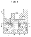
- Fig. 1 shows a side sectional construction of a cylinder head according to the embodiment.
- a cylinder head 10 has a bottom deck 11 that forms a bottom face of the cylinder head 10 and a top deck 12 that forms a top face of the cylinder head 10.
- a water jacket 14, 15 for circulating cooling water is formed between the bottom deck 11 and the top deck 12.
- a middle deck 13 is formed between the bottom deck 11 and the top deck 12.
- the water jacket 14, 15 is formed by two layer portions divided vertically by the middle deck 13, that is, an upper-layer water jacket 15 and a lower-layer water jacket 14. Cooling water for cooling the cylinder head 10 is first conducted through the lower-layer water jacket 14, and then conducted into the upper-layer water jacket 15 in a returning manner. Thus, cooling water flows through the lower-layer water jacket 14 and the upper-layer water jacket 15 in opposite directions as indicated by arrows in Fig. 1.
- the water jacket is vertically divided into two stages, and cooling water is conducted through the lower-layer water jacket 14 and the upper-layer water jacket 15 in that order.
- cooling water is conducted through the lower-layer water jacket 14 and the upper-layer water jacket 15 in that order.
- the cylinder head 10 has a housing boss portion 17 in which a housing hole 16 for housing a fuel injector is formed.
- the housing boss portion 17 extends vertically through the lower-layer water jacket 14 and the upper-layer water jacket 15.
- the cylinder head 10 has a structure for fastening and securing a fuel injector disposed in the housing hole 16 to the cylinder head 10.
- Fig. 2 shows a fragmental side sectional view of the cylinder head 10, illustrating the structure for securing a fuel injector to the cylinder head 10 and its surrounding structure.
- a clamp 22 is placed so as to extend from an upper portion of a fuel injector 20 housed in the housing boss portion 17 to a head portion of a cam cap bolt 25 securing a cam cap 24, as shown in Fig. 2.
- the clamp 22 is secured to an upper portion of the cylinder head 10 by a fastening bolt 23 inserted through a central portion of the clamp 22.
- the cylinder head 10 has a fastening bolt boss portion 19 having a bolt hole 18 into which the fastening bolt 23 is screwed.
- the fastening bolt boss portion 19 extends through the upper-layer water jacket 15 to interconnect the top deck 12, which forms an upper partition of the upper-layer water jacket 15, and the middle deck 13, which forms a lower partition of the upper-layer water jacket 15.
- the clamp 22 By screwing the fastening bolt 23 into the bolt hole 18 and tightening the fastening bolt 23, the clamp 22 is forced to press the fuel injector 20 from above while a portion of the clamp 22 contacting the head portion of the cam cap bolt 25 is serving as a fulcrum. As a result, the fuel injector 20 is fastened and secured in the housing hole 16 while being urged downward.
- the fuel injector 20 is urged downward when fastened and secured as described. Therefore, the fastening bolt boss portion 19 coupled to the fastening bolt 23 is urged upward by the axial tension of the fastening bolt 23.
- the top deck 12 and the middle deck 13 are partially interconnected by the fastening bolt boss portion 19 as described above, so that the rigidity of portions around the fastening bolt boss portion 19 of the cylinder head 10 is increased. Therefore, those portions of the cylinder head 10 of the embodiment are suitably prevented from being deformed by a force acting along an axis of the fastening bolt 23. As a result, it becomes possible to fasten and secure the fuel injector 20 more firmly and stably.
- the rigidity of the entire cylinder head 10 can also be increased by the fastening bolt boss portion 19 connecting the top deck 12 and the middle deck 13.
- the fastening bolt boss portion 19 takes up a space in the upper-layer water jacket 15, the fastening bolt boss portion 19 does not block the cooling water passage through the upper-layer water jacket 15. Therefore, good cooling effect of the upper-layer water jacket 15 is maintained.
- the cooling structure of the cylinder head 10 of the embodiment and, more particularly, the cooling structure in the upper-layer water jacket 15 will be described below.
- Fig. 3 is a plan sectional view of the cylinder head 10 taken on line III-III in Fig. 1, illustrating a horizontal sectional construction of the cylinder head 10 including that of the upper-layer water jacket 15.
- the flow of cooling water in the upper-layer water jacket 15 is indicated by arrows.
- the fastening bolt boss portion 19 of the cylinder head 10 of the embodiment is provided downstream of the housing boss portion 17 housing the fuel injector 20 in terms of the flowing direction of cooling water in the upper-layer water jacket 15. Therefore, the fastening bolt boss portion 19 does not impede the flow of cooling water near the housing boss portion 17, so that the provision of the fastening bolt boss portion 19 does not reduce the injector cooling efficiency.
- fastening bolt boss portion 19 extends to interconnect the upper partition and the lower partition of the upper-layer water jacket 15, there is a possibility of slightly impeding the flow of cooling water in the upper-layer water jacket 15.
- cooling water is allowed to flow substantially freely near the fastening bolt boss portion 19, so that the cooling effect on the surroundings of the fastening bolt boss portion 19 will not deteriorate.
- the cylinder head 10 of the embodiment achieves various excellent advantages as stated below.
- connection of the top deck 12 and the middle deck 13 by the fastening bolt boss portion 19 also increases the rigidity of the entire cylinder head 10.
- fastening bolt boss portion 19 is provided downstream of the housing boss portion 17 in terms of the flowing direction of cooling water, adverse effect of the provision of the fastening bolt boss portion 19 on the cooling of the fuel injector 20 is avoided.
- fastening bolt boss portion 19 extends to interconnect the upper partition and the lower partition of the upper-layer water jacket 15, there is a possibility of slightly impeding the flow of cooling water in the upper-layer water jacket 15.
- cooling water is allowed to flow substantially freely near the fastening bolt boss portion 19, so that the cooling effect on the surroundings of the fastening bolt boss portion 19 will not deteriorate.
- the invention is not limited to the foregoing embodiment, but may also be embodied in various other manners, for example, in manners modified from the foregoing embodiment as described below.
- the fastening bolt boss portion 19 is provided downstream of the housing boss portion 17 in terms of the flowing direction of cooling water, at such a position that cooling water sufficiently flows around the housing boss portion 17.
- the position of the fastening bolt boss portion 19 can be arbitrarily determined.
- the invention is applied to the cylinder head having the upper and lower water jacket divisions 14, 15, the invention may also be applied to a cylinder head having more than two vertically divided water jacket portions, in a manner similar to the foregoing embodiment. If a fastening bolt boss portion is formed so as to extend through the uppermost water jacket portion and interconnect decks corresponding to the upper and lower partitions of the uppermost water jacket portion, it is possible to achieve advantages similar to those achieved by the foregoing embodiment.
- the invention is applied to the direct injection type diesel engine cylinder head
- the invention may also be applied to cylinder heads of other types of internal combustion engines, for example, a cylinder head of an in-cylinder direct fuel injection type gasoline engine, or the like, in a manner similar to the foregoing embodiment.
- the invention is applicable to any cylinder head as long as the cylinder head has a construction in which a water jacket is formed by a plurality of water jacket portions vertically divided by partitions and a fuel injector is fastened and secured to an upper portion of the cylinder by using a clamp and a fastening bolt.
- the invention can be effectively applied to a case where the fuel injector is of an in-cylinder direct fuel injection type.
- the fuel injector may also be of a type other than the in-cylinder direct injection type.
- a cylinder head 10 has two water jacket portions 14, 15 that are vertically divided by a middle deck 13.
- a clamp 22 extends over an upper portion of a fuel injector 22.
- the clamp 22 is fastened to the cylinder head 10 by a fastening bolt 23, so that the fuel injector 20 is fastened and secured to an upper portion of the cylinder head 10 while being urged downward.
- a fastening bolt boss portion 19 into which the fastening bolt 23 is screwed extends through the upper water jacket 15 and interconnects the middle deck 13 and a top deck 12, which form a lower partition and an upper partition of the upper water jacket 15, respectively.
- a cylinder head (10) has two water jacket portions (14, 15) that are vertically divided by a middle deck (13).
- a clamp (22) extends over an upper portion of a fuel injector (22).
- the clamp (22) is fastened to the cylinder head (10) by a fastening bolt (23), so that the fuel injector (20) is fastened and secured to an upper portion of the cylinder head (10) while being urged downward.
- a fastening bolt boss portion (19) into which the fastening bolt (23) is screwed extends through the upper water jacket (15) and interconnects the middle deck (13) and a top deck (12), which form a lower partition and an upper partition of the upper water jacket (15), respectively.
Landscapes
- Engineering & Computer Science (AREA)
- Chemical & Material Sciences (AREA)
- Combustion & Propulsion (AREA)
- Mechanical Engineering (AREA)
- General Engineering & Computer Science (AREA)
- Cylinder Crankcases Of Internal Combustion Engines (AREA)
- Fuel-Injection Apparatus (AREA)
Abstract
Description
- The present invention relates to a cylinder head of an internal combustion engine and, more particularly, to a construction of the cylinder head suitable for use in an in-cylinder direct injection type internal combustion engine.
- In a direct injection type diesel engine in which fuel injectors are disposed at sites in an upper portion of a cylinder head corresponding to upper central portions of combustion chambers, each fuel injector is disposed in a housing hole extending through the upper portion of the cylinder head. A conventional structure for fastening a fuel injector disposed in a housing hole to a cylinder head is described in, for example, Japanese Patent Application Laid-Open No. HEI 10-82355. In this fastening structure, a clamp is placed so as to extend from an upper portion of the fuel injector to an upper portion of the cylinder head. The clamp is pressed toward the upper portion of the cylinder head by a fastening bolt inserted through the clamp into the upper portion of the cylinder head from an upper face of the clamp. Adoption of this fastening structure makes it possible to firmly fasten fuel injectors to an upper portion of a cylinder head even if the fuel injectors are designed to inject high-pressure fuel into the corresponding cylinders as in a direct injection type diesel engine.
- In a cooling structure of a cylinder head described in Japanese Patent Application Laid-Open No. SHOU 61-175217, a water jacket for circulating cooling water is divided into an upper portion and a lower portion in the cylinder head. In the cylinder head, cooling water is conducted through the lower water jacket portion and the upper water jacket portion in that order. Therefore, a portion of the cylinder head adjacent to the combustion chambers, that is, a lower portion of the cylinder head where the heat load is high, can be cooled with precedence over other portions of the cylinder head, so that the cylinder head cooling efficiency improves.
- Although both the injector fastening structure of a direct injection type internal combustion engine and the cooling structure of the cylinder head to which fuel injectors are fastened as described above are excellent structures, a combination of the two structures will have an unignorable problem as described below.
- Fig. 4 is a side sectional view of a portion of a cylinder head around a fuel injector, wherein the cylinder head has upper and lower water jacket divisions and incorporates an injector fastening structure as described above.
- Referring to Fig. 4, upper and lower-
stage water jackets bottom deck 51 that forms a bottom face of acylinder head 50 and atop deck 52 that forms a top face of thecylinder head 50. The twowater jackets middle deck 53. - The
cylinder head 50 hasinjector housing holes 55 that extend through thebottom deck 51 and thetop deck 52. Afuel injector 56 is disposed in eachhousing hole 55 in a manner as shown in Fig. 4. Disposed on top of thecylinder head 50 is aclamp 60 that extends from a protrusion formed in an upper portion of thecylinder head 50 to an upper portion of thefuel injector 56. A fasteningbolt 61 is inserted through a central portion of theclamp 60. A distal end of the fasteningbolt 61 is screwed into a fasteningbolt boss 62 formed in thetop deck 52 of thecylinder head 50. - By tightening the fastening
bolt 61, theclamp 60 is forced to press thefuel injector 56 from above with a cylinder head-contacting portion of theclamp 60 serving as a fulcrum. As a result, thefuel injector 56 is fastened and secured to thecylinder head 50 while being urged downward. - In this structure, however, if the wall thickness of the
top deck 52 is increased in order to increase the bolt-fastening force caused by thefastening bolt boss 62, there occurs a problem that thecylinder head 50 becomes large in size, or a problem that the sectional area of theupper water jacket 54a decreases. Therefore, an attempt to secure a sufficient tightening force of the fasteningbolt 61 may result in upward deformation of a portion of thetop deck 52 surrounding theboss 62. If such deformation occurs, the fastening force on thefuel injector 56 decreases so that thefuel injector 56 cannot be stably secured. - Accordingly, it is an object of the invention to provide an internal combustion engine cylinder head that makes it possible to stably secure fuel injectors even if the cylinder head is provided with a plurality of water jacket portions divided vertically by partitions.
- This object is achieved by a cylinder head of an internal combustion engine comprising the features of claim 1. Further advantageously features are the subject-matters of the dependent claims.
- In accordance with the invention, there is provided a cylinder head of an internal combustion engine comprising plurality of water jackets vertically divided by partitions, wherein a clamp extending over an upper portion of a fuel injector is fastened to an upper portion of the cylinder head by a fastening bolt. The cylinder head is characterized in that a fastening bolt boss portion into which the fastening bolt is screwed extends through an uppermost water jacket of the plurality of vertically divided water jackets and interconnects an upper partition of the uppermost water jacket and a lower partition of the uppermost water jacket.
- In this cylinder head, the upper partition and the lower partition of the uppermost water jacket are partially interconnected by the fastening bolt boss portion, so that those connected portions of the cylinder head have increased rigidities and, therefore, deformation of a portion near the fastening bolt boss portion can be suitably prevented. Therefore, even if the fuel injector is of a type that is designed to inject high-pressure fuel, such as a direct injection type or the like, the fuel injector can be firmly and stably fastened and secured to the cylinder head. Although the fastening bolt boss portion takes up a space in the uppermost water jacket, the fastening bolt boss portion does not block the passage of cooling water in the uppermost water jacket. Therefore, good cooling effect of the uppermost water jacket is maintained.
- In the cylinder head of the invention, cooling water may be allowed to flow around the fastening bolt boss portion in the uppermost water jacket.
- Therefore, although the interconnection of the upper and lower partitions by the fastening bolt boss portion provides a possibility of slightly impeding the flow of cooling water in the uppermost water jacket, cooling water is allowed to flow around the fastening bolt boss portion, so that the cooling effect on a portion surrounding the fastening bolt boss portion will not deteriorate.
- In the above-described cylinder head, the fastening bolt boss portion may be formed downstream of the fuel injector in terms of a flowing direction of cooling water in the uppermost water jacket.
- If the fastening bolt boss portion is positioned downstream of the fuel injector in terms of the flowing direction of cooling water, impediment of the flow of cooling water around the fuel injector caused by the fastening bolt boss portion is avoided. The above-described construction also avoids an undesired event that cooling water warmed by the heat from the fastening bolt boss portion directly flows to the fuel injector. Therefore, it becomes possible to enhance the fastening of the fuel injector and increase the rigidity of the cylinder head while maintaining high injector cooling performance.
- The foregoing and further objects, features and advantages of the present invention will become apparent from the following description of preferred embodiments with reference to the accompanying drawings, wherein like numerals are used to represent like elements and wherein:
- Fig. 1 is a fragmental sectional view of an embodiment of the cylinder head of the invention, illustrating a side sectional construction thereof;
- Fig. 2 is a fragmental sectional view of the cylinder head shown in Fig. 1, illustrating an injector fastening structure thereof;
- Fig. 3 is a sectional view taken on line III-III in Fig. 1; and
- Fig 4 is a fragmental sectional view of a conventional cylinder head, illustrating a side sectional construction around an injector fastening portion.
-
- A preferred embodiment in which the cylinder head of an internal combustion engine of the invention is embodied as a cylinder head of a direct injection type diesel engine will be described in detail below.
- Fig. 1 shows a side sectional construction of a cylinder head according to the embodiment.
- Referring to Fig. 1, a
cylinder head 10 has abottom deck 11 that forms a bottom face of thecylinder head 10 and atop deck 12 that forms a top face of thecylinder head 10. Awater jacket bottom deck 11 and thetop deck 12. Amiddle deck 13 is formed between thebottom deck 11 and thetop deck 12. Thewater jacket middle deck 13, that is, an upper-layer water jacket 15 and a lower-layer water jacket 14. Cooling water for cooling thecylinder head 10 is first conducted through the lower-layer water jacket 14, and then conducted into the upper-layer water jacket 15 in a returning manner. Thus, cooling water flows through the lower-layer water jacket 14 and the upper-layer water jacket 15 in opposite directions as indicated by arrows in Fig. 1. - In the
cylinder head 10 of the embodiment, the water jacket is vertically divided into two stages, and cooling water is conducted through the lower-layer water jacket 14 and the upper-layer water jacket 15 in that order. In this manner, a portion of thecylinder head 10 adjacent to the combustion chambers, that is, a lower portion of thecylinder head 10 in which the heat load is relatively high, is cooled with precedence over other portions of thecylinder head 10, thereby improving the cooling efficiency. - The
cylinder head 10 has ahousing boss portion 17 in which ahousing hole 16 for housing a fuel injector is formed. Thehousing boss portion 17 extends vertically through the lower-layer water jacket 14 and the upper-layer water jacket 15. Thecylinder head 10 has a structure for fastening and securing a fuel injector disposed in thehousing hole 16 to thecylinder head 10. - Fig. 2 shows a fragmental side sectional view of the
cylinder head 10, illustrating the structure for securing a fuel injector to thecylinder head 10 and its surrounding structure. - In the
cylinder head 10, aclamp 22 is placed so as to extend from an upper portion of afuel injector 20 housed in thehousing boss portion 17 to a head portion of acam cap bolt 25 securing acam cap 24, as shown in Fig. 2. Theclamp 22 is secured to an upper portion of thecylinder head 10 by afastening bolt 23 inserted through a central portion of theclamp 22. - The
cylinder head 10 has a fasteningbolt boss portion 19 having abolt hole 18 into which thefastening bolt 23 is screwed. The fasteningbolt boss portion 19 extends through the upper-layer water jacket 15 to interconnect thetop deck 12, which forms an upper partition of the upper-layer water jacket 15, and themiddle deck 13, which forms a lower partition of the upper-layer water jacket 15. - By screwing the
fastening bolt 23 into thebolt hole 18 and tightening thefastening bolt 23, theclamp 22 is forced to press thefuel injector 20 from above while a portion of theclamp 22 contacting the head portion of thecam cap bolt 25 is serving as a fulcrum. As a result, thefuel injector 20 is fastened and secured in thehousing hole 16 while being urged downward. - In this fastening structure, the
fuel injector 20 is urged downward when fastened and secured as described. Therefore, the fasteningbolt boss portion 19 coupled to thefastening bolt 23 is urged upward by the axial tension of thefastening bolt 23. In thecylinder head 10 of the embodiment, however, thetop deck 12 and themiddle deck 13 are partially interconnected by the fasteningbolt boss portion 19 as described above, so that the rigidity of portions around the fasteningbolt boss portion 19 of thecylinder head 10 is increased. Therefore, those portions of thecylinder head 10 of the embodiment are suitably prevented from being deformed by a force acting along an axis of thefastening bolt 23. As a result, it becomes possible to fasten and secure thefuel injector 20 more firmly and stably. - The rigidity of the
entire cylinder head 10 can also be increased by the fasteningbolt boss portion 19 connecting thetop deck 12 and themiddle deck 13. - Although the fastening
bolt boss portion 19 takes up a space in the upper-layer water jacket 15, the fasteningbolt boss portion 19 does not block the cooling water passage through the upper-layer water jacket 15. Therefore, good cooling effect of the upper-layer water jacket 15 is maintained. - The cooling structure of the
cylinder head 10 of the embodiment and, more particularly, the cooling structure in the upper-layer water jacket 15 will be described below. - Fig. 3 is a plan sectional view of the
cylinder head 10 taken on line III-III in Fig. 1, illustrating a horizontal sectional construction of thecylinder head 10 including that of the upper-layer water jacket 15. In Fig. 3, the flow of cooling water in the upper-layer water jacket 15 is indicated by arrows. - As shown in Fig. 3, the fastening
bolt boss portion 19 of thecylinder head 10 of the embodiment is provided downstream of thehousing boss portion 17 housing thefuel injector 20 in terms of the flowing direction of cooling water in the upper-layer water jacket 15. Therefore, the fasteningbolt boss portion 19 does not impede the flow of cooling water near thehousing boss portion 17, so that the provision of the fasteningbolt boss portion 19 does not reduce the injector cooling efficiency. - Furthermore, since the fastening
bolt boss portion 19 extends to interconnect the upper partition and the lower partition of the upper-layer water jacket 15, there is a possibility of slightly impeding the flow of cooling water in the upper-layer water jacket 15. However, cooling water is allowed to flow substantially freely near the fasteningbolt boss portion 19, so that the cooling effect on the surroundings of the fasteningbolt boss portion 19 will not deteriorate. - As can be understood from the above description, the
cylinder head 10 of the embodiment achieves various excellent advantages as stated below. - Since the
top deck 12 and themiddle deck 13 are partially interconnected by the fasteningbolt boss portion 19, those connected portions of thecylinder head 10 have increased rigidities, so that the portions are suitably prevented from being deformed by an axial force of thefastening bolt 23. Therefore, it becomes possible to fasten and secure thefuel injector 20 more firmly and stably. Even if thefuel injector 20 is of a type that is designed to inject high-pressure fuel, thefuel injector 20 can be firmly and stably fastened and secured to thecylinder head 10. - The connection of the
top deck 12 and themiddle deck 13 by the fasteningbolt boss portion 19 also increases the rigidity of theentire cylinder head 10. - Furthermore, since the fastening
bolt boss portion 19 is provided downstream of thehousing boss portion 17 in terms of the flowing direction of cooling water, adverse effect of the provision of the fasteningbolt boss portion 19 on the cooling of thefuel injector 20 is avoided. - Further, since the fastening
bolt boss portion 19 extends to interconnect the upper partition and the lower partition of the upper-layer water jacket 15, there is a possibility of slightly impeding the flow of cooling water in the upper-layer water jacket 15. However, cooling water is allowed to flow substantially freely near the fasteningbolt boss portion 19, so that the cooling effect on the surroundings of the fasteningbolt boss portion 19 will not deteriorate. - The invention is not limited to the foregoing embodiment, but may also be embodied in various other manners, for example, in manners modified from the foregoing embodiment as described below.
- In the foregoing embodiment, the fastening
bolt boss portion 19 is provided downstream of thehousing boss portion 17 in terms of the flowing direction of cooling water, at such a position that cooling water sufficiently flows around thehousing boss portion 17. However, the position of the fasteningbolt boss portion 19 can be arbitrarily determined. An advantage is that the provision of the fasteningbolt boss portion 19 extending through the upper-layer water jacket 15 to interconnect thetop deck 12 and themiddle deck 13 enhances the fastening of a fuel injector while increasing the rigidity of the water jacket structure even if the water jacket structure is divided into upper and lower portions. - Although in the aforementioned embodiment, the invention is applied to the cylinder head having the upper and lower
water jacket divisions - Still further, although in the foregoing embodiment, the invention is applied to the direct injection type diesel engine cylinder head, the invention may also be applied to cylinder heads of other types of internal combustion engines, for example, a cylinder head of an in-cylinder direct fuel injection type gasoline engine, or the like, in a manner similar to the foregoing embodiment. The invention is applicable to any cylinder head as long as the cylinder head has a construction in which a water jacket is formed by a plurality of water jacket portions vertically divided by partitions and a fuel injector is fastened and secured to an upper portion of the cylinder by using a clamp and a fastening bolt. The invention can be effectively applied to a case where the fuel injector is of an in-cylinder direct fuel injection type. However, according to the invention, the fuel injector may also be of a type other than the in-cylinder direct injection type.
- A
cylinder head 10 has twowater jacket portions middle deck 13. Aclamp 22 extends over an upper portion of afuel injector 22. Theclamp 22 is fastened to thecylinder head 10 by afastening bolt 23, so that thefuel injector 20 is fastened and secured to an upper portion of thecylinder head 10 while being urged downward. A fasteningbolt boss portion 19 into which thefastening bolt 23 is screwed extends through theupper water jacket 15 and interconnects themiddle deck 13 and atop deck 12, which form a lower partition and an upper partition of theupper water jacket 15, respectively. - A cylinder head (10) has two water jacket portions (14, 15) that are vertically divided by a middle deck (13). A clamp (22) extends over an upper portion of a fuel injector (22). The clamp (22) is fastened to the cylinder head (10) by a fastening bolt (23), so that the fuel injector (20) is fastened and secured to an upper portion of the cylinder head (10) while being urged downward. A fastening bolt boss portion (19) into which the fastening bolt (23) is screwed extends through the upper water jacket (15) and interconnects the middle deck (13) and a top deck (12), which form a lower partition and an upper partition of the upper water jacket (15), respectively.
- Selected drawing: Fig. 2
Claims (5)
- A cylinder head (10) of an internal combustion engine comprising a plurality of water jackets (14, 15) vertically divided by partitions, wherein a clamp (22) extending over an upper portion of a fuel injector (20) is fastened to an upper portion of the cylinder head (10) by a fastening bolt (23),the cylinder head (10) being characterized in that a fastening bolt boss portion (19) into which the fastening bolt (23) is screwed extends through an uppermost water jacket (15) of the plurality of vertically divided water jackets and interconnects an upper partition (12) of the uppermost water jacket (15) and at least a lower partition (13) of the uppermost water jacket.
- A cylinder head of an internal combustion engine according to claim 1, characterized in that in the uppermost water jacket (15), the fastening bolt boss portion (19) is arranged such that the cooling water is allowed to flow around the fastening bolt boss portion (19).
- A cylinder head of an internal combustion engine according to claim 2, characterized in that the fuel injector (20) extends through the uppermost water jacket (15) and is secured to the cylinder head (10).
- A cylinder head of an internal combustion engine according to claim 3, characterized in that the fastening bolt boss portion (19) is formed downstream of the fuel injector (20) in terms of a flowing direction of cooling water in the uppermost water jacket (15).
- A cylinder head of an internal combustion engine according to claim 1, characterized in that the internal combustion engine is an in-cylinder direct injection type internal combustion engine.
Applications Claiming Priority (2)
| Application Number | Priority Date | Filing Date | Title |
|---|---|---|---|
| JP11031345A JP2000230457A (en) | 1999-02-09 | 1999-02-09 | Cylinder head of internal combustion engine |
| JP3134599 | 1999-02-09 |
Publications (2)
| Publication Number | Publication Date |
|---|---|
| EP1028246A2 true EP1028246A2 (en) | 2000-08-16 |
| EP1028246A3 EP1028246A3 (en) | 2001-07-04 |
Family
ID=12328652
Family Applications (1)
| Application Number | Title | Priority Date | Filing Date |
|---|---|---|---|
| EP00102453A Withdrawn EP1028246A3 (en) | 1999-02-09 | 2000-02-04 | Cylinder head of internal combustion engine |
Country Status (2)
| Country | Link |
|---|---|
| EP (1) | EP1028246A3 (en) |
| JP (1) | JP2000230457A (en) |
Cited By (6)
| Publication number | Priority date | Publication date | Assignee | Title |
|---|---|---|---|---|
| WO2004001214A1 (en) * | 2002-06-21 | 2003-12-31 | Fev Motorentechnik Gmbh | Cooled cylinder head for a reciprocating engine |
| WO2006072333A1 (en) * | 2004-12-24 | 2006-07-13 | Fev Motorentechnik Gmbh | Cylinder head with reinforcement |
| CN103485921A (en) * | 2013-09-24 | 2014-01-01 | 中国北方发动机研究所(天津) | Uniform cooling double-layer-water-cavity cylinder cover for highly-intensified diesel engine |
| CN110439705A (en) * | 2019-07-02 | 2019-11-12 | 广西玉柴机器股份有限公司 | A kind of cylinder cover cooling structure |
| CN111765016A (en) * | 2020-07-10 | 2020-10-13 | 王飞飞 | A V-shaped cylinder head blank |
| CN115506912A (en) * | 2022-08-22 | 2022-12-23 | 中国北方发动机研究所(天津) | Cylinder head cooling water cavity |
Families Citing this family (1)
| Publication number | Priority date | Publication date | Assignee | Title |
|---|---|---|---|---|
| KR100828795B1 (en) * | 2006-12-13 | 2008-05-09 | 현대자동차주식회사 | Middle deck rigid reinforcement structure of cylinder head |
Citations (1)
| Publication number | Priority date | Publication date | Assignee | Title |
|---|---|---|---|---|
| JPS61175217A (en) | 1985-01-29 | 1986-08-06 | Mazda Motor Corp | Cooling structure for cylinder head |
Family Cites Families (3)
| Publication number | Priority date | Publication date | Assignee | Title |
|---|---|---|---|---|
| US2234780A (en) * | 1938-12-16 | 1941-03-11 | Gen Motors Corp | Cylinder head construction |
| GB828014A (en) * | 1957-05-20 | 1960-02-10 | Fodens Ltd | Improvements in the cooling system of the cylinder head of a diesel engine |
| US3405696A (en) * | 1966-06-01 | 1968-10-15 | Gen Motors Corp | Individual cylinder head for internal combustion engine |
-
1999
- 1999-02-09 JP JP11031345A patent/JP2000230457A/en active Pending
-
2000
- 2000-02-04 EP EP00102453A patent/EP1028246A3/en not_active Withdrawn
Patent Citations (1)
| Publication number | Priority date | Publication date | Assignee | Title |
|---|---|---|---|---|
| JPS61175217A (en) | 1985-01-29 | 1986-08-06 | Mazda Motor Corp | Cooling structure for cylinder head |
Cited By (10)
| Publication number | Priority date | Publication date | Assignee | Title |
|---|---|---|---|---|
| WO2004001214A1 (en) * | 2002-06-21 | 2003-12-31 | Fev Motorentechnik Gmbh | Cooled cylinder head for a reciprocating engine |
| US6973897B2 (en) | 2002-06-21 | 2005-12-13 | Fev Motorentechnik Gmbh | Cooled cylinder head for a reciprocating engine |
| CN100340759C (en) * | 2002-06-21 | 2007-10-03 | Fev电机技术有限公司 | Cooled cylinder head for a reciprocating engine |
| WO2006072333A1 (en) * | 2004-12-24 | 2006-07-13 | Fev Motorentechnik Gmbh | Cylinder head with reinforcement |
| US8001935B2 (en) | 2004-12-24 | 2011-08-23 | Fev Motorentechnik Gmbh | Cylinder head with reinforcement |
| CN103485921A (en) * | 2013-09-24 | 2014-01-01 | 中国北方发动机研究所(天津) | Uniform cooling double-layer-water-cavity cylinder cover for highly-intensified diesel engine |
| CN110439705A (en) * | 2019-07-02 | 2019-11-12 | 广西玉柴机器股份有限公司 | A kind of cylinder cover cooling structure |
| CN110439705B (en) * | 2019-07-02 | 2024-05-10 | 广西玉柴机器股份有限公司 | Cylinder cover cooling structure |
| CN111765016A (en) * | 2020-07-10 | 2020-10-13 | 王飞飞 | A V-shaped cylinder head blank |
| CN115506912A (en) * | 2022-08-22 | 2022-12-23 | 中国北方发动机研究所(天津) | Cylinder head cooling water cavity |
Also Published As
| Publication number | Publication date |
|---|---|
| EP1028246A3 (en) | 2001-07-04 |
| JP2000230457A (en) | 2000-08-22 |
Similar Documents
| Publication | Publication Date | Title |
|---|---|---|
| EP0628716B1 (en) | Cylinder block for an internal combustion engine | |
| KR101027791B1 (en) | Mounting Structure of Direct Fuel Rail | |
| EP1028247B1 (en) | Cylinder head of internal combustion engine | |
| EP1028246A2 (en) | Cylinder head of internal combustion engine | |
| JP2000073853A (en) | Fuel cylinder injection type engine | |
| US6382145B2 (en) | Reed valve cooling apparatus for engine | |
| EP2698522B1 (en) | Cylinder head of internal combustion engine | |
| US7520256B2 (en) | Fastening structure for cylinder head and divided type cylinder block of engine | |
| US8001935B2 (en) | Cylinder head with reinforcement | |
| US5400750A (en) | Manifold and plenum construction for an electronic fuel injected engine | |
| JPS6224777Y2 (en) | ||
| JP2001027150A (en) | Internal combustion engine provided with cylinder head having peculiar bolt fitting and port layout | |
| JPH029087Y2 (en) | ||
| JP2010151063A (en) | Cylinder block | |
| JP2836416B2 (en) | Structure of cylinder block of internal combustion engine | |
| JPH11200941A (en) | Engine structure | |
| US7077079B2 (en) | Cylinder block of internal combustion engine | |
| JPH10318040A (en) | Cylinder block of internal combustion engine | |
| JP4134819B2 (en) | Cylinder block | |
| JP3401116B2 (en) | Engine cylinder head structure | |
| JP3494335B2 (en) | Internal combustion engine | |
| JP4012754B2 (en) | Closed breather device for diesel engine | |
| US6880520B2 (en) | Direct injection diesel engine | |
| JP3500871B2 (en) | Engine structure | |
| JPH0313547Y2 (en) |
Legal Events
| Date | Code | Title | Description |
|---|---|---|---|
| PUAI | Public reference made under article 153(3) epc to a published international application that has entered the european phase |
Free format text: ORIGINAL CODE: 0009012 |
|
| 17P | Request for examination filed |
Effective date: 20000204 |
|
| AK | Designated contracting states |
Kind code of ref document: A2 Designated state(s): AT BE CH CY DE DK ES FI FR GB GR IE IT LI LU MC NL PT SE |
|
| AX | Request for extension of the european patent |
Free format text: AL;LT;LV;MK;RO;SI |
|
| PUAL | Search report despatched |
Free format text: ORIGINAL CODE: 0009013 |
|
| AK | Designated contracting states |
Kind code of ref document: A3 Designated state(s): AT BE CH CY DE DK ES FI FR GB GR IE IT LI LU MC NL PT SE |
|
| AX | Request for extension of the european patent |
Free format text: AL;LT;LV;MK;RO;SI |
|
| RIC1 | Information provided on ipc code assigned before grant |
Free format text: 7F 02F 1/42 A, 7F 02F 1/40 B, 7F 02F 1/24 B |
|
| STAA | Information on the status of an ep patent application or granted ep patent |
Free format text: STATUS: THE APPLICATION HAS BEEN WITHDRAWN |
|
| 18W | Application withdrawn |
Withdrawal date: 20010720 |