EP1028169A2 - Reticulated foam structures - Google Patents
Reticulated foam structures Download PDFInfo
- Publication number
- EP1028169A2 EP1028169A2 EP00300809A EP00300809A EP1028169A2 EP 1028169 A2 EP1028169 A2 EP 1028169A2 EP 00300809 A EP00300809 A EP 00300809A EP 00300809 A EP00300809 A EP 00300809A EP 1028169 A2 EP1028169 A2 EP 1028169A2
- Authority
- EP
- European Patent Office
- Prior art keywords
- metal
- mould
- gas
- gasifier
- cryogen
- Prior art date
- Legal status (The legal status is an assumption and is not a legal conclusion. Google has not performed a legal analysis and makes no representation as to the accuracy of the status listed.)
- Granted
Links
Images
Classifications
-
- B—PERFORMING OPERATIONS; TRANSPORTING
- B22—CASTING; POWDER METALLURGY
- B22F—WORKING METALLIC POWDER; MANUFACTURE OF ARTICLES FROM METALLIC POWDER; MAKING METALLIC POWDER; APPARATUS OR DEVICES SPECIALLY ADAPTED FOR METALLIC POWDER
- B22F3/00—Manufacture of workpieces or articles from metallic powder characterised by the manner of compacting or sintering; Apparatus specially adapted therefor ; Presses and furnaces
- B22F3/10—Sintering only
- B22F3/11—Making porous workpieces or articles
- B22F3/1121—Making porous workpieces or articles by using decomposable, meltable or sublimatable fillers
- B22F3/1125—Making porous workpieces or articles by using decomposable, meltable or sublimatable fillers involving a foaming process
-
- B—PERFORMING OPERATIONS; TRANSPORTING
- B22—CASTING; POWDER METALLURGY
- B22F—WORKING METALLIC POWDER; MANUFACTURE OF ARTICLES FROM METALLIC POWDER; MAKING METALLIC POWDER; APPARATUS OR DEVICES SPECIALLY ADAPTED FOR METALLIC POWDER
- B22F2999/00—Aspects linked to processes or compositions used in powder metallurgy
Definitions
- Foam structures are known in industry and the number of applications for metallic foam structures is continually increasing.
- aluminium foam metal having a continuously connected, open celled (reticulated) geometry is available and employed in :-
- the high surface to volume ratio allows for a compact design and the high specific stiffness, that is, high strength to weight ratio makes the material useful in aerospace and car applications.
- Low-cost aluminium foam panels can be produced by a continuous casting process.
- the foam is machinable by common aluminium metal working techniques (sawing, drilling, milling) and maybe joined by brazing or adhesive bonding.
- aluminium foam produced by this method finds application as lightweight cores for sandwich panels and as components in energy absorbing structures.
- metal foams are formed typically by mixing small quantities of a gasifier e.g. titanium nitride with aluminium powder and subjecting the mixture to heat and pressure to form a sintered sheet.
- a gasifier e.g. titanium nitride
- the sintered sheet or a portion thereof is then placed in a mould which is then heated to a higher temperature at which the metal melts and nitrogen is released from the titanium nitride to provide an even dispersion of bubbles.
- the hot metal is allowed to solidify and then shock heat treated by dropping it into a cryogen such as liquid nitrogen which causes small fractures to occur between adjacent bubbles so that the mass becomes reticulated.
- a cryogen such as liquid nitrogen which causes small fractures to occur between adjacent bubbles so that the mass becomes reticulated.
- This quenching process can be controlled by monitoring the temperature of the metal before it is quenched in the cryogen. However, the rate of cooling and the temperature difference may still be insufficient to produce the necessary reticulated structure.
- a method of making a metal foam object comprises the steps of :-
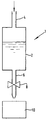
- the apparatus 1 includes a heat insulated pressure vessel 2 containing a cryogen, for example, liquid nitrogen.
- a cryogen for example, liquid nitrogen.
- An inlet pipe 4 is in communication with the ullage space at the top of the liquid cryogen and an outlet pipe 6 is located at or adjacent the base of the vessel 2 as illustrated.
- the flow of liquid / gas from the vessel 2 and through the pipe 6 is controlled by a valve 8.
- the vessel 2 is pressurised to 5 barg by passing a gas through the inlet pipe 4 and the liquid cryogen is then expanded through the valve 8 and the outlet pipe assembly 6 such that a high velocity mixture of gas and liquid droplets impinges upon the object 10 to be quenched.
- the high velocity gas liquid droplet stream will extract heat from the block 10 many times faster than dipping the block 10 in liquid nitrogen since the film boiling effect which prevents the liquid nitrogen from touching block is avoided.
Landscapes
- Engineering & Computer Science (AREA)
- Manufacturing & Machinery (AREA)
- Mechanical Engineering (AREA)
- Powder Metallurgy (AREA)
Abstract
Description
Preferably the cryogen is nitrogen, the gasifier is titanium nitride and the metal is aluminium.
Claims (3)
- A method of making a metal foam object comprising the steps of:mixing a gasifier with metal powder and subjecting the mixture to an elevated temperature T1 and pressure P1 to form a sintered sheet;placing a least a portion of the sintered sheet into a mould and subjecting the mould to a temperature T2 where T2 is greater than T1 at which the metal melts and the gas is released from the gasifier; andquenching the metal foam object thus formed in the mould, in which the quenching is carried out by applying a cryogen to the object as a high velocity mixture of gas and liquid droplets.
- A method as claimed in claim 1, in which the cryogen is nitrogen.
- A method as claimed in claim 1 or 2 in which the gasifier is titanium nitride and the metal is aluminium.
Applications Claiming Priority (2)
| Application Number | Priority Date | Filing Date | Title |
|---|---|---|---|
| GB9903276 | 1999-02-12 | ||
| GBGB9903276.5A GB9903276D0 (en) | 1999-02-12 | 1999-02-12 | Reticulated foam structutes |
Publications (3)
| Publication Number | Publication Date |
|---|---|
| EP1028169A2 true EP1028169A2 (en) | 2000-08-16 |
| EP1028169A3 EP1028169A3 (en) | 2000-09-06 |
| EP1028169B1 EP1028169B1 (en) | 2003-05-02 |
Family
ID=10847699
Family Applications (1)
| Application Number | Title | Priority Date | Filing Date |
|---|---|---|---|
| EP00300809A Expired - Lifetime EP1028169B1 (en) | 1999-02-12 | 2000-02-02 | Reticulated foam structures |
Country Status (4)
| Country | Link |
|---|---|
| US (1) | US6458316B1 (en) |
| EP (1) | EP1028169B1 (en) |
| DE (1) | DE60002376T2 (en) |
| GB (1) | GB9903276D0 (en) |
Cited By (3)
| Publication number | Priority date | Publication date | Assignee | Title |
|---|---|---|---|---|
| WO2001021346A1 (en) * | 1999-09-23 | 2001-03-29 | Messer Griesheim Gmbh | Method and device for foaming metals or metal alloys |
| EP2415542A4 (en) * | 2009-03-30 | 2018-03-28 | Mitsubishi Materials Corporation | Process for producing porous sintered aluminum, and porous sintered aluminum |
| EP2415543A4 (en) * | 2009-03-30 | 2018-03-28 | Mitsubishi Materials Corporation | Process for producing porous sintered aluminum, and porous sintered aluminum |
Families Citing this family (3)
| Publication number | Priority date | Publication date | Assignee | Title |
|---|---|---|---|---|
| JP2006528515A (en) | 2003-07-24 | 2006-12-21 | テコメット・インコーポレーテッド | Spongy structure |
| WO2007112554A1 (en) * | 2006-03-30 | 2007-10-11 | Metafoam Technologies Inc. | Method for partially coating open cell porous materials |
| US9514916B2 (en) * | 2013-03-15 | 2016-12-06 | Varian Semiconductor Equipment Associates, Inc. | Wafer platen thermosyphon cooling system |
Family Cites Families (5)
| Publication number | Priority date | Publication date | Assignee | Title |
|---|---|---|---|---|
| US3847591A (en) * | 1971-06-21 | 1974-11-12 | Ethyl Corp | Lead-zinc foams |
| US4099961A (en) * | 1976-12-21 | 1978-07-11 | The United States Of America As Represented By The United States Department Of Energy | Closed cell metal foam method |
| US4614544A (en) * | 1985-01-23 | 1986-09-30 | E. I. Du Pont De Nemours And Company | High strength powder metal parts |
| DE4018360C1 (en) * | 1990-06-08 | 1991-05-29 | Fraunhofer-Gesellschaft Zur Foerderung Der Angewandten Forschung Ev, 8000 Muenchen, De | Porous metal body prodn. - involves compaction at low temp. followed by heating to near melting point of metal |
| DE4101630A1 (en) * | 1990-06-08 | 1991-12-12 | Fraunhofer Ges Forschung | METHOD FOR PRODUCING FOAMABLE METAL BODIES AND USE THEREOF |
-
1999
- 1999-02-12 GB GBGB9903276.5A patent/GB9903276D0/en not_active Ceased
-
2000
- 2000-02-02 DE DE60002376T patent/DE60002376T2/en not_active Expired - Fee Related
- 2000-02-02 EP EP00300809A patent/EP1028169B1/en not_active Expired - Lifetime
- 2000-02-09 US US09/500,678 patent/US6458316B1/en not_active Expired - Fee Related
Cited By (3)
| Publication number | Priority date | Publication date | Assignee | Title |
|---|---|---|---|---|
| WO2001021346A1 (en) * | 1999-09-23 | 2001-03-29 | Messer Griesheim Gmbh | Method and device for foaming metals or metal alloys |
| EP2415542A4 (en) * | 2009-03-30 | 2018-03-28 | Mitsubishi Materials Corporation | Process for producing porous sintered aluminum, and porous sintered aluminum |
| EP2415543A4 (en) * | 2009-03-30 | 2018-03-28 | Mitsubishi Materials Corporation | Process for producing porous sintered aluminum, and porous sintered aluminum |
Also Published As
| Publication number | Publication date |
|---|---|
| US6458316B1 (en) | 2002-10-01 |
| EP1028169A3 (en) | 2000-09-06 |
| GB9903276D0 (en) | 1999-04-07 |
| DE60002376T2 (en) | 2004-02-12 |
| EP1028169B1 (en) | 2003-05-02 |
| DE60002376D1 (en) | 2003-06-05 |
Similar Documents
| Publication | Publication Date | Title |
|---|---|---|
| Ünal | Effect of processing variables on particle size in gas atomization of rapidly solidified aluminium powders | |
| Skorokhod et al. | Correlation between the particle size, pore size, and porous structure of sintered tungsten | |
| CA1059500A (en) | Liquid heat exchanger interface and method | |
| Sakaki et al. | Effect of the increase in the entrance convergent section length of the gun nozzle on the high-velocity oxygen fuel and cold spray process | |
| Abu-Lebdeh et al. | Gas atomization of molten metal: part II. Applications | |
| US20070183919A1 (en) | Method of forming metal foams by cold spray technique | |
| EP1028169B1 (en) | Reticulated foam structures | |
| WO2004109211B1 (en) | Method for making brazed heat exchanger and apparatus | |
| Sazegaran | Investigation on production parameters of steel foam manufactured through powder metallurgical space holder technique | |
| Van Steenkiste | Kinetic spray: a new coating process | |
| GB2366298A (en) | Forming metal foam structures by cold-gas spraying | |
| US6585111B1 (en) | Metal foam container | |
| Aamir et al. | Ultra fast spray cooling and critical droplet diameter estimation from cooling rate | |
| US7297178B2 (en) | Method and device for producing spherical metal particles | |
| Vardelle et al. | Transport and chemical rate phenomena in plasma sprays | |
| Solonenko | Criterion conditions for the formation of hollow microspheres from plasma-treated agglomerated particles | |
| Champagne et al. | The effects of gas and metal characteristics on sprayed metal coatings | |
| KR101366721B1 (en) | Improved method for preparation metal-matrix composite and device for implementing said method | |
| Wang et al. | Numerical and experimental investigation of vacuum-assisted laser welding for DP590 galvanized steel lap joint without prescribed gap | |
| US6444166B1 (en) | Reticulated foam structures | |
| US2774566A (en) | Fluid cooled permeable turbine blade | |
| Ferdows | Numerical approach on parameters of the thermal radiation interaction with convection in a boundary layer flow at a vertical plate with variable suction | |
| Gourdin | Local microstructural modification in dynamically consolidated metal powders | |
| Liu et al. | Collision morphologies supercooled water droplets on small low-temperature superhydrophobic spherical targets | |
| CN116574943A (en) | A preparation method of aluminum foam containing ceramic balls based on strong magnetic field |
Legal Events
| Date | Code | Title | Description |
|---|---|---|---|
| PUAI | Public reference made under article 153(3) epc to a published international application that has entered the european phase |
Free format text: ORIGINAL CODE: 0009012 |
|
| PUAL | Search report despatched |
Free format text: ORIGINAL CODE: 0009013 |
|
| AK | Designated contracting states |
Kind code of ref document: A2 Designated state(s): DE FR GB IT NL |
|
| AX | Request for extension of the european patent |
Free format text: AL;LT;LV;MK;RO;SI |
|
| AK | Designated contracting states |
Kind code of ref document: A3 Designated state(s): AT BE CH CY DE DK ES FI FR GB GR IE IT LI LU MC NL PT SE |
|
| AX | Request for extension of the european patent |
Free format text: AL;LT;LV;MK;RO;SI |
|
| RIC1 | Information provided on ipc code assigned before grant |
Free format text: 7C 22C 1/08 A, 7B 22F 3/11 B |
|
| 17P | Request for examination filed |
Effective date: 20010123 |
|
| AKX | Designation fees paid |
Free format text: DE FR GB IT NL |
|
| GRAH | Despatch of communication of intention to grant a patent |
Free format text: ORIGINAL CODE: EPIDOS IGRA |
|
| GRAH | Despatch of communication of intention to grant a patent |
Free format text: ORIGINAL CODE: EPIDOS IGRA |
|
| GRAA | (expected) grant |
Free format text: ORIGINAL CODE: 0009210 |
|
| AK | Designated contracting states |
Designated state(s): DE FR GB IT NL |
|
| PG25 | Lapsed in a contracting state [announced via postgrant information from national office to epo] |
Ref country code: IT Free format text: LAPSE BECAUSE OF FAILURE TO SUBMIT A TRANSLATION OF THE DESCRIPTION OR TO PAY THE FEE WITHIN THE PRESCRIBED TIME-LIMIT;WARNING: LAPSES OF ITALIAN PATENTS WITH EFFECTIVE DATE BEFORE 2007 MAY HAVE OCCURRED AT ANY TIME BEFORE 2007. THE CORRECT EFFECTIVE DATE MAY BE DIFFERENT FROM THE ONE RECORDED. Effective date: 20030502 Ref country code: NL Free format text: LAPSE BECAUSE OF FAILURE TO SUBMIT A TRANSLATION OF THE DESCRIPTION OR TO PAY THE FEE WITHIN THE PRESCRIBED TIME-LIMIT Effective date: 20030502 |
|
| REG | Reference to a national code |
Ref country code: GB Ref legal event code: FG4D |
|
| REF | Corresponds to: |
Ref document number: 60002376 Country of ref document: DE Date of ref document: 20030605 Kind code of ref document: P |
|
| NLV1 | Nl: lapsed or annulled due to failure to fulfill the requirements of art. 29p and 29m of the patents act | ||
| PG25 | Lapsed in a contracting state [announced via postgrant information from national office to epo] |
Ref country code: GB Free format text: LAPSE BECAUSE OF NON-PAYMENT OF DUE FEES Effective date: 20040202 |
|
| ET | Fr: translation filed | ||
| PLBE | No opposition filed within time limit |
Free format text: ORIGINAL CODE: 0009261 |
|
| STAA | Information on the status of an ep patent application or granted ep patent |
Free format text: STATUS: NO OPPOSITION FILED WITHIN TIME LIMIT |
|
| 26N | No opposition filed |
Effective date: 20040203 |
|
| PG25 | Lapsed in a contracting state [announced via postgrant information from national office to epo] |
Ref country code: DE Free format text: LAPSE BECAUSE OF NON-PAYMENT OF DUE FEES Effective date: 20040901 |
|
| GBPC | Gb: european patent ceased through non-payment of renewal fee |
Effective date: 20040202 |
|
| PG25 | Lapsed in a contracting state [announced via postgrant information from national office to epo] |
Ref country code: FR Free format text: LAPSE BECAUSE OF NON-PAYMENT OF DUE FEES Effective date: 20041029 |
|
| REG | Reference to a national code |
Ref country code: FR Ref legal event code: ST |