EP1027558B1 - A safety cut-off device - Google Patents
A safety cut-off device Download PDFInfo
- Publication number
- EP1027558B1 EP1027558B1 EP97938808A EP97938808A EP1027558B1 EP 1027558 B1 EP1027558 B1 EP 1027558B1 EP 97938808 A EP97938808 A EP 97938808A EP 97938808 A EP97938808 A EP 97938808A EP 1027558 B1 EP1027558 B1 EP 1027558B1
- Authority
- EP
- European Patent Office
- Prior art keywords
- safety
- voltage
- cut
- thermoelectric
- thermocouple
- Prior art date
- Legal status (The legal status is an assumption and is not a legal conclusion. Google has not performed a legal analysis and makes no representation as to the accuracy of the status listed.)
- Expired - Lifetime
Links
Images

Classifications
-
- F—MECHANICAL ENGINEERING; LIGHTING; HEATING; WEAPONS; BLASTING
- F23—COMBUSTION APPARATUS; COMBUSTION PROCESSES
- F23N—REGULATING OR CONTROLLING COMBUSTION
- F23N5/00—Systems for controlling combustion
- F23N5/02—Systems for controlling combustion using devices responsive to thermal changes or to thermal expansion of a medium
- F23N5/10—Systems for controlling combustion using devices responsive to thermal changes or to thermal expansion of a medium using thermocouples
- F23N5/102—Systems for controlling combustion using devices responsive to thermal changes or to thermal expansion of a medium using thermocouples using electronic means
-
- F—MECHANICAL ENGINEERING; LIGHTING; HEATING; WEAPONS; BLASTING
- F23—COMBUSTION APPARATUS; COMBUSTION PROCESSES
- F23D—BURNERS
- F23D14/00—Burners for combustion of a gas, e.g. of a gas stored under pressure as a liquid
- F23D14/46—Details, e.g. noise reduction means
- F23D14/72—Safety devices, e.g. operative in case of failure of gas supply
-
- F—MECHANICAL ENGINEERING; LIGHTING; HEATING; WEAPONS; BLASTING
- F24—HEATING; RANGES; VENTILATING
- F24C—DOMESTIC STOVES OR RANGES ; DETAILS OF DOMESTIC STOVES OR RANGES, OF GENERAL APPLICATION
- F24C3/00—Stoves or ranges for gaseous fuels
- F24C3/12—Arrangement or mounting of control or safety devices
- F24C3/126—Arrangement or mounting of control or safety devices on ranges
Definitions
- the invention relates to a safety cut-off device for a gas-heated hob comprising a thermocouple and a thermoelectric generator as well as a safety solenoid valve.
- thermocouple which gives off a voltage when it it is heated by the lit flame, and this voltage is sufficient to deliver a holding current for a solenoid safety valve in the gas supply.
- a system of this kind may have a push-button to perform the initial mechanical actuation of the solenid valve whereby the gas flows and may be lit, possibly by electronic means, and when the thermocouple has been heated, it sustains the open position of the safety valve.
- EP 0 635 680 it is known to use a series connection of safety valves to increase the security, and one thermocouple functions as above described and a neighbouring thermeoelectric generator (a series connection of several thermojunctions) supplies an activation and holding current for a separate solenoid valve in series with the first mentioned.
- thermoelectric voltage generators are large which means that they will supply holding currents for many seconds after a flame has disappeared, irrespective of the reason for the disappearance of the flame. This means that unburnt gas escapes for many seconds which will create an explosion hazard when the admixture of air is suitable. Also, first turning-on of the main flame is relatively slow this way.
- thermoelectric generator provides the supply voltage for a transistor amplifier controlling the holding current for the safety solenoid valve, said transistor amplifier being controlled by the thermoelectric voltage from the thermocouple in order to cut off the holding current at a predetermined thermoelectric voltage.
- a preferred embodiment is particular in that the transistor amplifier is a DC coupled common emitter amplifier with the collector connected to the thermeoelectric generator, the emitter to the solenoid, and the base to the thermocouple.
- An advantageous embodiment further comprises a battery source for providing a short-term actuating voltage for the safety valve.
- a further advantageous embodiment uses the battery source to power a spark ignition electrode at the hob.
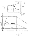
- Fig. 1 shows the voltages generated in a thermoelectric junction and in a generator consisting of a series connection of such junctions. It will be seen that the time constant of the series connection is less than the time constant of the single junction, but that the actual voltage of the single junction has an overshoot before it settles at a stable, temperature dependent voltage.
- the holding voltage of a magnet used in a safety device is low (although the current may be fairly high), and it is shown in relation to the other voltages present in such appliances.
- the time constant of the cooling down after a source of heat has disappeared is considerable, and about 6 times as large as the heating-up time constant.
- a safety cut-out based on the current generated by the voltage of a thermo-junction would let a fair amount of gas escape before the cut-out is effective.
- Fig. 2 is shown a simple emitter-follower type amplifier in which a thermoelectric generator 1 supplies the drive voltage and the sensing thermojunction 2 provides the input signal to a transistor 3 amplifier.
- the solenoid 4 of a magnetic safety valve is connected to the emitter of the transistor 3.
- a silicon transistor will tolerate operating temperatures of ca. 150°C which is ample in practice.
- the voltages shown graphicaly in Fig. 1 are shown in the schematic, and it will be understood that suitable dimensioning of the base resistor, based on the voltage drops inherent in transistor operation and a knowledge of the resistance of the solenoid for the magnetic valve, will result in a control of the current from the emitter through the solenoid.
- a cut-off is obtained when the voltage from the thermojunction has fallen only a little with respect to the stable high-temperature condition.
- Fig. 1 is shown that the gas would continue to flow about 6 times longer, if the safety valve did not release until the voltage had fallen by the thermal time constant alone.
- Fig. 3 is shown the lay-out "below the top" of a gas hob fitted with electronic ignition of the gas and a safety device according to the invention.
- a gas burner is generally indicated by the grid at 5, and an ignition electrode 6 is connected to a high-voltage generator 7 supplied by a battery 8 which is remote from the gas burner. Ignition is controlled by the gas valve 9 which is combined with a safety cut-out of the magnetic type. Ordinarily, this valve is actuated by the gas valve during and immediately after ignition, until sufficient holding voltage is available from a thermoelectric source.
- thermoelectric source Such sources are indicated as a thermojunction 10 and a thermoelectric generator 11. As described above, the thermovoltages generated are fed to an amplifier 12 which is connected to the solenoid in the safety valve 13.
- thermogenerator and the thermojunction very quickly increase above the holding voltage of the solenoid, and it is not an undue strain on the ignition battery to supply the higher actuation voltage and the solenoid current during the brief period just after ingnition, until the transistor amplifier can take over. This avoids the combination with a mechanical actuation directly from the valve 9.
Description
Claims (4)
- A safety cut-off device for a gas-heated hob comprising a thermocouple and a thermoelectric generator as well as a safety solenoid valve,
characterized in that the thermoelectric generator (1) provides the supply voltage for a transistor amplifier (3) controlling the holding current for the safety solenoid valve, said transistor amplifier being controlled by the thermoelectric voltage from the thermocouple (2) in order to cut off the holding current at a predetermined thermoelectric voltage. - A safety cut-out device according to claim 1,
characterized in that the transistor amplifier is a DC coupled common emitter amplifier with the collector connected to the thermeoelectric generator (1), the emitter to the solenoid (4) and the base to the thermocouple (2). - A safety cut-out device according to claim 1,
characterized in that it comprises a battery source (8) for providing a short-term actuating voltage for the safety valve. - A safety cut-out device according to claim 3,
characterized in that it uses the battery source to power a spark ignition electrode (6) at the hob.
Applications Claiming Priority (1)
| Application Number | Priority Date | Filing Date | Title |
|---|---|---|---|
| PCT/DK1997/000366 WO1999011979A1 (en) | 1997-08-28 | 1997-08-28 | A safety cut-off device |
Publications (2)
| Publication Number | Publication Date |
|---|---|
| EP1027558A1 EP1027558A1 (en) | 2000-08-16 |
| EP1027558B1 true EP1027558B1 (en) | 2002-01-30 |
Family
ID=8156223
Family Applications (1)
| Application Number | Title | Priority Date | Filing Date |
|---|---|---|---|
| EP97938808A Expired - Lifetime EP1027558B1 (en) | 1997-08-28 | 1997-08-28 | A safety cut-off device |
Country Status (6)
| Country | Link |
|---|---|
| EP (1) | EP1027558B1 (en) |
| AU (1) | AU4113097A (en) |
| DE (1) | DE69710229T2 (en) |
| DK (1) | DK1027558T3 (en) |
| ES (1) | ES2171990T3 (en) |
| WO (1) | WO1999011979A1 (en) |
Families Citing this family (4)
| Publication number | Priority date | Publication date | Assignee | Title |
|---|---|---|---|---|
| AUPR152400A0 (en) * | 2000-11-16 | 2000-12-14 | Garcia, Fernando Teodoro | Shut-off safety system and gas applicance including same |
| AU2002214834B2 (en) * | 2000-11-16 | 2006-11-16 | Fernando Teodoro Garcia | Shut-off safety system and gas appliance including same |
| ITMI20010222U1 (en) * | 2001-04-19 | 2002-10-21 | Whirlpool Co | SAFETY DEVICE FOR DOMESTIC GAS COOKING APPLIANCES |
| ITTO20120457A1 (en) * | 2012-05-25 | 2013-11-26 | Eltek Spa | CONTROL DEVICE FOR GAS TAPS |
Family Cites Families (1)
| Publication number | Priority date | Publication date | Assignee | Title |
|---|---|---|---|---|
| IT1264955B1 (en) * | 1993-07-20 | 1996-10-17 | Sit La Precisa Spa | ACTUATOR FOR GAS BURNER WITH FLAME SAFETY AND ADJUSTMENT SOLENOID VALVE. |
-
1997
- 1997-08-28 AU AU41130/97A patent/AU4113097A/en not_active Abandoned
- 1997-08-28 DE DE69710229T patent/DE69710229T2/en not_active Expired - Fee Related
- 1997-08-28 WO PCT/DK1997/000366 patent/WO1999011979A1/en active IP Right Grant
- 1997-08-28 EP EP97938808A patent/EP1027558B1/en not_active Expired - Lifetime
- 1997-08-28 DK DK97938808T patent/DK1027558T3/en active
- 1997-08-28 ES ES97938808T patent/ES2171990T3/en not_active Expired - Lifetime
Also Published As
| Publication number | Publication date |
|---|---|
| DE69710229T2 (en) | 2002-10-24 |
| AU4113097A (en) | 1999-03-22 |
| ES2171990T3 (en) | 2002-09-16 |
| EP1027558A1 (en) | 2000-08-16 |
| DE69710229D1 (en) | 2002-03-14 |
| WO1999011979A1 (en) | 1999-03-11 |
| DK1027558T3 (en) | 2002-05-06 |
Similar Documents
| Publication | Publication Date | Title |
|---|---|---|
| US6474979B1 (en) | Device and method for triggering a gas furnace ignitor | |
| ITMI952569A1 (en) | COOKING APPLIANCE WITH AT LEAST ONE COVERED COOKING FIELD AND ONE RADIATION BURNER UNIT | |
| US3941553A (en) | Heater safety control system | |
| US6644957B2 (en) | Damper control device | |
| US4265612A (en) | Intermittent pulsing gas ignition system | |
| US3174534A (en) | Spark ignition system for gas burners | |
| US6698417B2 (en) | Device for obtaining rapid ignition of a cooking hob gas burner fed via a gas pipe provided with a solenoid safety valve | |
| EP1027558B1 (en) | A safety cut-off device | |
| US2294694A (en) | Control system | |
| US2527286A (en) | Safety shutoff control for plural pilot gaseous fuel burner systems | |
| US4002419A (en) | Direct burner ignition system | |
| US2518804A (en) | Safety control system for gaseous fuel burners | |
| US4529373A (en) | Burner safety ignition system allowing for electrical and manual operation | |
| US4806095A (en) | Fuel valve control system | |
| ES374067A1 (en) | Heating apparatus for caravans and the like | |
| US3358738A (en) | Heat responsive switch control | |
| US3153440A (en) | Electric igniting and fuel supply control arrangement for fuel burners | |
| US3807933A (en) | Ignition and control system for gas burners | |
| US7690916B2 (en) | Method and apparatus for operating a gas-powered cooking and frying device | |
| EP0454613B1 (en) | Gas appliance | |
| US2477216A (en) | Control and ignition system for fuel burners | |
| US3493174A (en) | Forced air temperature control systems | |
| US2564851A (en) | Safety control and ignition system for fuel burners | |
| US2747656A (en) | Electric ignition system for an oil burner | |
| US2720623A (en) | Thermoelectric generators |
Legal Events
| Date | Code | Title | Description |
|---|---|---|---|
| PUAI | Public reference made under article 153(3) epc to a published international application that has entered the european phase |
Free format text: ORIGINAL CODE: 0009012 |
|
| 17P | Request for examination filed |
Effective date: 20000403 |
|
| AK | Designated contracting states |
Kind code of ref document: A1 Designated state(s): DE DK ES IT |
|
| GRAG | Despatch of communication of intention to grant |
Free format text: ORIGINAL CODE: EPIDOS AGRA |
|
| 17Q | First examination report despatched |
Effective date: 20010322 |
|
| GRAG | Despatch of communication of intention to grant |
Free format text: ORIGINAL CODE: EPIDOS AGRA |
|
| GRAH | Despatch of communication of intention to grant a patent |
Free format text: ORIGINAL CODE: EPIDOS IGRA |
|
| GRAH | Despatch of communication of intention to grant a patent |
Free format text: ORIGINAL CODE: EPIDOS IGRA |
|
| GRAA | (expected) grant |
Free format text: ORIGINAL CODE: 0009210 |
|
| AK | Designated contracting states |
Kind code of ref document: B1 Designated state(s): DE DK ES IT |
|
| REF | Corresponds to: |
Ref document number: 69710229 Country of ref document: DE Date of ref document: 20020314 |
|
| REG | Reference to a national code |
Ref country code: DK Ref legal event code: T3 |
|
| REG | Reference to a national code |
Ref country code: ES Ref legal event code: FG2A Ref document number: 2171990 Country of ref document: ES Kind code of ref document: T3 |
|
| PLBE | No opposition filed within time limit |
Free format text: ORIGINAL CODE: 0009261 |
|
| STAA | Information on the status of an ep patent application or granted ep patent |
Free format text: STATUS: NO OPPOSITION FILED WITHIN TIME LIMIT |
|
| 26N | No opposition filed | ||
| PGFP | Annual fee paid to national office [announced via postgrant information from national office to epo] |
Ref country code: DK Payment date: 20070815 Year of fee payment: 11 |
|
| PGFP | Annual fee paid to national office [announced via postgrant information from national office to epo] |
Ref country code: DE Payment date: 20070823 Year of fee payment: 11 |
|
| PGFP | Annual fee paid to national office [announced via postgrant information from national office to epo] |
Ref country code: ES Payment date: 20070926 Year of fee payment: 11 |
|
| PGFP | Annual fee paid to national office [announced via postgrant information from national office to epo] |
Ref country code: IT Payment date: 20070829 Year of fee payment: 11 |
|
| REG | Reference to a national code |
Ref country code: DK Ref legal event code: EBP |
|
| PG25 | Lapsed in a contracting state [announced via postgrant information from national office to epo] |
Ref country code: DK Free format text: LAPSE BECAUSE OF NON-PAYMENT OF DUE FEES Effective date: 20080831 |
|
| PG25 | Lapsed in a contracting state [announced via postgrant information from national office to epo] |
Ref country code: IT Free format text: LAPSE BECAUSE OF NON-PAYMENT OF DUE FEES Effective date: 20080828 Ref country code: DE Free format text: LAPSE BECAUSE OF NON-PAYMENT OF DUE FEES Effective date: 20090303 |
|
| REG | Reference to a national code |
Ref country code: ES Ref legal event code: FD2A Effective date: 20080829 |
|
| PG25 | Lapsed in a contracting state [announced via postgrant information from national office to epo] |
Ref country code: ES Free format text: LAPSE BECAUSE OF NON-PAYMENT OF DUE FEES Effective date: 20080829 |