EP1027276B1 - Procedure for installing a landing door, and a corresponding installation system - Google Patents
Procedure for installing a landing door, and a corresponding installation system Download PDFInfo
- Publication number
- EP1027276B1 EP1027276B1 EP98949014A EP98949014A EP1027276B1 EP 1027276 B1 EP1027276 B1 EP 1027276B1 EP 98949014 A EP98949014 A EP 98949014A EP 98949014 A EP98949014 A EP 98949014A EP 1027276 B1 EP1027276 B1 EP 1027276B1
- Authority
- EP
- European Patent Office
- Prior art keywords
- lintel
- overhead supporter
- side posts
- wall
- installation
- Prior art date
- Legal status (The legal status is an assumption and is not a legal conclusion. Google has not performed a legal analysis and makes no representation as to the accuracy of the status listed.)
- Expired - Lifetime
Links
- 238000009434 installation Methods 0.000 title claims description 26
- 238000000034 method Methods 0.000 title claims description 10
- 230000000284 resting effect Effects 0.000 claims description 6
- 210000002105 tongue Anatomy 0.000 claims description 2
- 239000000725 suspension Substances 0.000 claims 2
- 238000005259 measurement Methods 0.000 description 4
- 238000003466 welding Methods 0.000 description 3
- 238000010276 construction Methods 0.000 description 1
Images

Classifications
-
- B—PERFORMING OPERATIONS; TRANSPORTING
- B66—HOISTING; LIFTING; HAULING
- B66B—ELEVATORS; ESCALATORS OR MOVING WALKWAYS
- B66B13/00—Doors, gates, or other apparatus controlling access to, or exit from, cages or lift well landings
- B66B13/30—Constructional features of doors or gates
-
- B—PERFORMING OPERATIONS; TRANSPORTING
- B66—HOISTING; LIFTING; HAULING
- B66B—ELEVATORS; ESCALATORS OR MOVING WALKWAYS
- B66B13/00—Doors, gates, or other apparatus controlling access to, or exit from, cages or lift well landings
- B66B13/30—Constructional features of doors or gates
- B66B13/303—Details of door panels
Definitions
- the present invention relates to a procedure for installing a landing door as defined in claim 1 and to an installation system as defined in claim 4.
- a threshold module is mounted on the lower edge of the door opening, in a horizontal position and at the correct distance from the elevator car.
- the side posts are mounted at the side edges of the door opening to form door jambs, in a position as accurately vertical as possible and in alignment with the threshold module.
- the side posts can be connected by their upper ends together by a lintel, which can also be fastened by its ends to the edges of the door opening.
- the overhead supporter is fixed to the upper part of the door opening by lifting it up to its position and fastening it with bolts to the edges of the door opening in a position as accurately horizontal as possible, i.e. parallel to the threshold module.
- the prior-art procedure involves several drawbacks. Installation must be carried out by resorting to welding and observing relatively accurate measurements, so it imposes strict requirements regarding the dimensioning of the door opening. Installation is difficult and slow because practically every part of the door must be measured separately and mounted in the correct position relative to the door opening. The relatively heavy overhead supporter must be supported manually during the mounting and measurement. In addition, especially in high-rise elevator shafts, tolerance problems are encountered because the door openings must be relatively accurately positioned and sufficiently small to allow the door parts to be accurately installed in position.
- a procedure and a system for the installation of a landing door is already known for example from JP-A-10001275.
- the object of the present invention is to eliminate the drawbacks described above.
- a specific object of the invention is to present a new type of procedure and a corresponding system that makes it possible to assemble the landing door in as simple a manner as possible and without welding and laborious or difficult operations.
- a further object of the invention is to reduce the tolerance requirements regarding the construction of elevator shafts.
- a threshold module is mounted on the lower edge of the door opening, in a position as accurately horizontal as possible and in a suitable position relative to the depth dimension of the door opening.
- side posts of a length as precisely equal to each other as possible are mounted on top of the threshold module and attached to the threshold module by their lower ends, while the top ends of the side posts are connected to each other by a lintel mounted on top of them.
- the overhead supporter is lifted up and allowed to rest on the lintel. The overhead supporter remains in position as it is supported by the lintel and thus it can be easily fixed to the wall by its ends.
- the cross-measure of the door opening formed by the side posts and the lintel is taken and the door opening is straightened and attached to the wall before the overhead supporter is lifted into position. Another possibility is to lift the overhead supporter into position on the lintel and cross-measure the door opening only when the overhead supporter is being attached to the wall.
- the essential point in the procedure of the invention is that, after the threshold module has been mounted in position, no accurate measurements to determine the vertical or horizontal alignment of different parts are required, but the parts can be simply put together and bolted to the wall of the elevator shaft after only taking the cross-measure.
- the heavy overhead supporter need not be measured and fitted into position, but simply lifting it onto the lintel will suffice to make sure that the overhead supporter is in the correct position.
- the system of the invention for the installation of a landing door comprises a threshold module to be mounted on the lower edge of the door opening, side posts, a lintel and an overhead supporter, from which the door panels are suspended.
- the lintel mounted on..top of the side posts comprises fitting parts and the overhead supporter comprises corresponding brackets so that the overhead supporter can be lifted into position on the lintel, the overhead supporter remaining in its final mounting position on the lintel. After this, the overhead supporter can be locked or fixed to the lintel and also to the wall without having to be otherwise supported during the mounting operation.
- the fitting parts of the lintel preferably comprise slots, openings, sleeves, supporting pins or equivalent elements or areas for the brackets of the overhead supporter.
- the brackets preferably consist of tongues, pins, lugs or equivalent projections adapted to the fitting parts.
- the brackets can advantageously be shaped in different ways and different supporting structures can be added to the lintel.
- the fitting parts and brackets may be arranged the other way round on the lintel and overhead supporter, in other words, the essential point is that the lintel and the overhead supporter are provided with mutually corresponding elements that enable the overhead supporter to rest on the lintel by its own weight.
- the ends of the overhead supporter are preferably provided with fixing points by which the overhead supporter, resting on the lintel in precisely the correct position relative to the door opening, can be fixed to the wall.
- the lintel is preferably likewise provided with mounting brackets by which the lintel, resting on the side posts, can be attached to the wall after the cross-measurement of the door opening formed by the side posts and the lintel.
- the mounting brackets or their attachments to the wall are preferably of a flexible or sliding type to permit the assembly formed by the lintel and side posts to be moved to a suitable distance from the wall, i.e. to a precisely vertical position over the threshold module.
- the system of the invention for the installation of a landing door allows the door frame to be assembled from parts that need no welding. Thus, it will be possible to use pre-coated sheet material, resulting in obvious cost savings.
- the invention can be implemented using a lintel of a light structure that is easy to mount and adjust in position on the side posts while at the same time serving as a mounting jig and support for the overhead supporter. Therefore, the overhead supporter can be allowed to rest on the lintel and it can then be permanently fixed to the wall by its ends.
- the invention simplifies the process of constructing the elevator shaft as a whole because the entire door structure is measured and installed based on the lower edge of the door opening. Thus, the side and top edges of the door opening are not subject to any strict requirements regarding dimensional accuracy.
- a threshold module 2 is fixed to the lower edge of a door opening 1 of an elevator shaft, in a horizontal position and correctly positioned in the depth direction of the door opening 1.
- the threshold module 2 On its top, the threshold module 2 has mounting areas 11 to which the lower ends of the side posts 3 and 4 are attached as illustrated by Fig. 2.
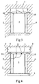
- a lintel 5 of a relatively light structure is mounted horizontally on top of the side posts 3 and 4.
- Each end of the lintel is provided with a mounting bracket 10 extending over the edge of the door opening onto the wall.
- the cross-measure of the opening formed by the side posts 3 and 4 and the lintel 5 is checked to ensure that the opening is straight, whereupon the lintel is preliminarily fastened to the wall from the holes at the ends of the mounting brackets 10.
- the vertical alignment of the side posts 3 and 4 on the threshold module 2 is checked and adjusted, whereupon the mounting brackets 10 are tightened in position on the wall.
- the overhead supporter 6 can be lifted onto the lintel so that its brackets 8 engage the pins 7 of the lintel.
- the overhead supporter 6 will remain in place without any additional support while at the same time being accurately positioned in its final installation position.
- the overhead supporter is therefore easy to fix permanently to the wall by the fixing points 9 at the ends by using suitable bolts.
- the overhead supporter 6 and the lintel 5 can be attached to each other by the fitting parts 7 and the brackets 8.
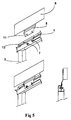
- Fig. 5 presents a detail of a preferred installation system, in which the bracket 8 is so shaped that lugs 11 comprised in the bracket 8 intermesh with a supporting structure 12 comprised in the lintel 5.
- the supporting structure 12 may be e.g. a shaped portion of the lintel 5, a separate part attached to the lintel 5 or some other supporting element.
Landscapes
- Elevator Door Apparatuses (AREA)
- Platform Screen Doors And Railroad Systems (AREA)
- Lift-Guide Devices, And Elevator Ropes And Cables (AREA)
Description
Claims (10)
- Procedure for the installation of a landing door wherein a threshold module (2) is mounted on the lower edge of a door opening (1) of an elevator shaft, where after equally long side posts (3,4) are mounted on top of the threshold module (2) at the edges of the opening, and a lintel (5) connecting the side posts is mounted on top of them as well as an overhead supporter (6) for the suspension of door panels is mounted in the upper part of the opening, the overhead supporter (6) is placed onto the lintel, so that it rests on the lintel, whereby the lintel and the overhead supporter comprise mutually corresponding elements (7,8) as to keep the overhead supporter on the lintel in its correct position by its own weight before the overhead supporter is fixed to the wall by its ends.
- Installation procedure as defined in claim 1, characterised in that the overhead supporter (6) resting on the lintel (5) is attached to the lintel.
- Installation procedure as defined in claim 1, characterized in that the side posts (3,4) and the lintel (5) are fixed to the wall before the overhead supporter is brought to rest on the lintel.
- System for the installation of landing door, comprising a threshold module (2) to be attached to the lower edge of the door opening (1) of an elevator shaft, side posts (3,4), a lintel (5) and an overhead supporter (6) for the suspension of door panels whereby the lintel (5) mounted on top of the side posts (3,4) and the overhead supporter (6) are provided with mutually corresponding fitting parts (7) and brackets (8) to allow the overhead supporter to be supported on the lintel by its own weight in its correct position before being fixed to the edge of the door opening.
- Installation system as defined in claim 4, characterised in that the fitting parts of the lintel (5) comprise slots, holes, sleeves, supporting pins or equivalent elements designed to engage the brackets (8).
- Installation system as defined in claim 4, characterised in that the brackets (8) consist of tongues, pins, lugs or equivalent projections fitting onto the fitting parts (7).
- Installation system as defined in claim 5, characterised in that lugs (11) or equivalent comprised in the bracket (8) engage supporting elements (12) comprised in the lintel (5).
- Installation system as defined in claim 4, characterised in that the ends of the overhead supporter (6) are provided with fixing points (9) to allow the overhead supporter, resting in position on the lintel, to be fixed to the wall.
- Installation system as defined in claim 4, characterized in that the lintel is provided with mounting brackets (10) by which the lintel, resting on the side posts can be attached to the wall.
- Installation system as defined in claim 8, characterised in that the mounting brackets comprise a flexible element to permit the lintel and side posts to be moved perpendicularly to the wall to a suitable distance from the wall.
Applications Claiming Priority (5)
| Application Number | Priority Date | Filing Date | Title |
|---|---|---|---|
| FI974158 | 1997-11-06 | ||
| FI974158A FI108294B (en) | 1997-11-06 | 1997-11-06 | Mounting procedure for a shaft door and corresponding mounting system |
| FI981992 | 1998-09-15 | ||
| FI981992A FI981992A0 (en) | 1997-11-06 | 1998-09-15 | Level door installation method and corresponding installation system |
| PCT/FI1998/000806 WO1999024347A1 (en) | 1997-11-06 | 1998-10-15 | Procedure for installing a landing door, and a corresponding installation system |
Publications (2)
| Publication Number | Publication Date |
|---|---|
| EP1027276A1 EP1027276A1 (en) | 2000-08-16 |
| EP1027276B1 true EP1027276B1 (en) | 2004-08-18 |
Family
ID=26160466
Family Applications (1)
| Application Number | Title | Priority Date | Filing Date |
|---|---|---|---|
| EP98949014A Expired - Lifetime EP1027276B1 (en) | 1997-11-06 | 1998-10-15 | Procedure for installing a landing door, and a corresponding installation system |
Country Status (10)
| Country | Link |
|---|---|
| US (1) | US6494001B1 (en) |
| EP (1) | EP1027276B1 (en) |
| JP (1) | JP2001522771A (en) |
| KR (1) | KR100424163B1 (en) |
| CN (1) | CN1176004C (en) |
| AU (1) | AU737268B2 (en) |
| BR (1) | BR9814953A (en) |
| DE (1) | DE69825773T2 (en) |
| FI (1) | FI981992A0 (en) |
| WO (1) | WO1999024347A1 (en) |
Cited By (1)
| Publication number | Priority date | Publication date | Assignee | Title |
|---|---|---|---|---|
| CN106395588A (en) * | 2016-10-20 | 2017-02-15 | 钟立朋 | Mounting frame of elevator landing door |
Families Citing this family (6)
| Publication number | Priority date | Publication date | Assignee | Title |
|---|---|---|---|---|
| ITBG20060012U1 (en) * | 2006-04-21 | 2007-10-22 | Sematic Italia Spa | PERFECTED PANEL FOR LIFT DOORS |
| JP5676496B2 (en) | 2009-03-13 | 2015-02-25 | オーチス エレベータ カンパニーOtis Elevator Company | Elevator system door frame supporting guide rail |
| CN102348629B (en) | 2009-03-13 | 2014-05-14 | 奥的斯电梯公司 | Elevator system with guide rail bracket |
| CN102285574A (en) * | 2011-08-29 | 2011-12-21 | 希姆斯电梯(中国)有限公司 | Installation structure of lift landing door |
| WO2019166685A1 (en) * | 2018-02-28 | 2019-09-06 | Kone Corporation | Elevator landing door assembly and its installation method |
| CN112173932B (en) * | 2020-10-20 | 2021-07-30 | 苏州美嘉智选电梯有限公司 | An elevator car door machine installation structure |
Family Cites Families (11)
| Publication number | Priority date | Publication date | Assignee | Title |
|---|---|---|---|---|
| US1321610A (en) * | 1919-11-11 | Metallic frame | ||
| GB826175A (en) | 1956-02-29 | 1959-12-31 | Otis Elevator Co | Elevator entrance sills |
| US3741351A (en) * | 1971-03-05 | 1973-06-26 | Westinghouse Electric Corp | Integrated elevator construction |
| US4561210A (en) * | 1984-02-21 | 1985-12-31 | Kvas Peter J | Sliding door |
| JP2502165B2 (en) * | 1990-04-13 | 1996-05-29 | 三菱電機株式会社 | Elevator hall door device |
| JP2503750B2 (en) * | 1990-09-27 | 1996-06-05 | 三菱電機株式会社 | Elevator hall device |
| DE59309501D1 (en) * | 1993-01-14 | 1999-05-12 | Inventio Ag | Method and device for installing shaft doors in lifts |
| FI94160C (en) * | 1993-04-23 | 1995-07-25 | Kone Oy | System for executing the entries for a lift's shaft doors |
| US5458828A (en) * | 1994-01-11 | 1995-10-17 | Chuang; Yung-Chuan | Method for constructing one-step grout fixed window frames in a concrete-structured building |
| IT235086Y1 (en) * | 1994-05-31 | 2000-03-31 | Selcom Spa | CONNECTION ELEMENT AND MULTI-FUNCTIONAL SUPPORT IN AUTOMATIC DOOR HANDLING MECHANISM FOR LIFTS AND ELEVATORS |
| JP3435990B2 (en) * | 1996-06-13 | 2003-08-11 | 三菱電機株式会社 | Elevator landing doorway device |
-
1998
- 1998-09-15 FI FI981992A patent/FI981992A0/en not_active Application Discontinuation
- 1998-10-15 EP EP98949014A patent/EP1027276B1/en not_active Expired - Lifetime
- 1998-10-15 DE DE1998625773 patent/DE69825773T2/en not_active Expired - Lifetime
- 1998-10-15 US US09/530,798 patent/US6494001B1/en not_active Expired - Lifetime
- 1998-10-15 JP JP2000520370A patent/JP2001522771A/en active Pending
- 1998-10-15 KR KR10-2000-7004946A patent/KR100424163B1/en not_active Expired - Fee Related
- 1998-10-15 WO PCT/FI1998/000806 patent/WO1999024347A1/en not_active Ceased
- 1998-10-15 BR BR9814953-9A patent/BR9814953A/en not_active IP Right Cessation
- 1998-10-15 AU AU95432/98A patent/AU737268B2/en not_active Ceased
- 1998-10-15 CN CNB98812145XA patent/CN1176004C/en not_active Expired - Lifetime
Cited By (1)
| Publication number | Priority date | Publication date | Assignee | Title |
|---|---|---|---|---|
| CN106395588A (en) * | 2016-10-20 | 2017-02-15 | 钟立朋 | Mounting frame of elevator landing door |
Also Published As
| Publication number | Publication date |
|---|---|
| HK1030766A1 (en) | 2001-05-18 |
| EP1027276A1 (en) | 2000-08-16 |
| CN1176004C (en) | 2004-11-17 |
| KR20010031870A (en) | 2001-04-16 |
| WO1999024347A1 (en) | 1999-05-20 |
| KR100424163B1 (en) | 2004-03-24 |
| BR9814953A (en) | 2000-10-03 |
| US6494001B1 (en) | 2002-12-17 |
| DE69825773T2 (en) | 2005-01-13 |
| DE69825773D1 (en) | 2004-09-23 |
| JP2001522771A (en) | 2001-11-20 |
| AU737268B2 (en) | 2001-08-16 |
| CN1281416A (en) | 2001-01-24 |
| AU9543298A (en) | 1999-05-31 |
| FI981992A0 (en) | 1998-09-15 |
Similar Documents
| Publication | Publication Date | Title |
|---|---|---|
| US6446762B1 (en) | Elevator machine support frame mounted to hoistway wall | |
| US6422352B1 (en) | Procedure and apparatus for the installation of an elevator | |
| US7818943B2 (en) | Track jack system | |
| CN102971245A (en) | Mounting components within an elevator | |
| AU737268B2 (en) | Procedure for installing a landing door, and a corresponding installation system | |
| US7788854B2 (en) | Elevator entrance door sill pivotable into and out of elevator shaft via hinge connected support and alignment brackets | |
| CN112408150B (en) | Guide rail bracket assembly | |
| US11498812B2 (en) | Elevator landing door assembly and its installation method | |
| JP6579591B1 (en) | Elevator landing device and installation method of elevator landing device | |
| JP4648543B2 (en) | Elevator floor structure | |
| CN118524982A (en) | Elevator car and method for installing multiple panels on a platform of an elevator car | |
| FI108294B (en) | Mounting procedure for a shaft door and corresponding mounting system | |
| JP2001522771A5 (en) | ||
| HK1030766B (en) | Procedure for installing a landing door, and a corresponding installation system | |
| JPH05319756A (en) | Door device for elevator hall | |
| JP2024162085A (en) | Structure mounting structure and structure mounting method | |
| SU1663153A1 (en) | Method of erection of constructions | |
| JPS60242282A (en) | Platform side access apparatus of elevator | |
| JP2002187686A (en) | New three-way elevator frame | |
| JPH04129982A (en) | Guide rail supporting device for diagonally running elevator | |
| HK1242284A1 (en) | Elevator system door frame that supports guide rails | |
| JPH08254026A (en) | Bath unit fitting structure of building unit | |
| JPH1087245A (en) | Elevator hall equipment | |
| JPH0229590B2 (en) | ||
| JP2000044149A (en) | Temporary holding device for elevator hall entrance unit |
Legal Events
| Date | Code | Title | Description |
|---|---|---|---|
| PUAI | Public reference made under article 153(3) epc to a published international application that has entered the european phase |
Free format text: ORIGINAL CODE: 0009012 |
|
| 17P | Request for examination filed |
Effective date: 20000531 |
|
| AK | Designated contracting states |
Kind code of ref document: A1 Designated state(s): DE FR GB IT NL |
|
| 17Q | First examination report despatched |
Effective date: 20020826 |
|
| GRAP | Despatch of communication of intention to grant a patent |
Free format text: ORIGINAL CODE: EPIDOSNIGR1 |
|
| GRAS | Grant fee paid |
Free format text: ORIGINAL CODE: EPIDOSNIGR3 |
|
| GRAA | (expected) grant |
Free format text: ORIGINAL CODE: 0009210 |
|
| AK | Designated contracting states |
Kind code of ref document: B1 Designated state(s): DE FR GB IT NL |
|
| REG | Reference to a national code |
Ref country code: GB Ref legal event code: FG4D |
|
| REF | Corresponds to: |
Ref document number: 69825773 Country of ref document: DE Date of ref document: 20040923 Kind code of ref document: P |
|
| PLBE | No opposition filed within time limit |
Free format text: ORIGINAL CODE: 0009261 |
|
| STAA | Information on the status of an ep patent application or granted ep patent |
Free format text: STATUS: NO OPPOSITION FILED WITHIN TIME LIMIT |
|
| ET | Fr: translation filed | ||
| 26N | No opposition filed |
Effective date: 20050519 |
|
| REG | Reference to a national code |
Ref country code: FR Ref legal event code: PLFP Year of fee payment: 18 |
|
| PGFP | Annual fee paid to national office [announced via postgrant information from national office to epo] |
Ref country code: IT Payment date: 20151026 Year of fee payment: 18 |
|
| REG | Reference to a national code |
Ref country code: FR Ref legal event code: PLFP Year of fee payment: 19 |
|
| PGFP | Annual fee paid to national office [announced via postgrant information from national office to epo] |
Ref country code: NL Payment date: 20161019 Year of fee payment: 19 Ref country code: GB Payment date: 20161020 Year of fee payment: 19 Ref country code: FR Payment date: 20161020 Year of fee payment: 19 |
|
| PG25 | Lapsed in a contracting state [announced via postgrant information from national office to epo] |
Ref country code: IT Free format text: LAPSE BECAUSE OF NON-PAYMENT OF DUE FEES Effective date: 20161015 |
|
| PGFP | Annual fee paid to national office [announced via postgrant information from national office to epo] |
Ref country code: DE Payment date: 20171019 Year of fee payment: 20 |
|
| REG | Reference to a national code |
Ref country code: NL Ref legal event code: MM Effective date: 20171101 |
|
| GBPC | Gb: european patent ceased through non-payment of renewal fee |
Effective date: 20171015 |
|
| REG | Reference to a national code |
Ref country code: FR Ref legal event code: ST Effective date: 20180629 |
|
| PG25 | Lapsed in a contracting state [announced via postgrant information from national office to epo] |
Ref country code: NL Free format text: LAPSE BECAUSE OF NON-PAYMENT OF DUE FEES Effective date: 20171101 Ref country code: GB Free format text: LAPSE BECAUSE OF NON-PAYMENT OF DUE FEES Effective date: 20171015 |
|
| PG25 | Lapsed in a contracting state [announced via postgrant information from national office to epo] |
Ref country code: FR Free format text: LAPSE BECAUSE OF NON-PAYMENT OF DUE FEES Effective date: 20171031 |
|
| REG | Reference to a national code |
Ref country code: DE Ref legal event code: R071 Ref document number: 69825773 Country of ref document: DE |