EP1026619A2 - Optical information reader and optical information reading system - Google Patents
Optical information reader and optical information reading system Download PDFInfo
- Publication number
- EP1026619A2 EP1026619A2 EP00300761A EP00300761A EP1026619A2 EP 1026619 A2 EP1026619 A2 EP 1026619A2 EP 00300761 A EP00300761 A EP 00300761A EP 00300761 A EP00300761 A EP 00300761A EP 1026619 A2 EP1026619 A2 EP 1026619A2
- Authority
- EP
- European Patent Office
- Prior art keywords
- signal
- image sensor
- optical information
- storing
- digitized
- Prior art date
- Legal status (The legal status is an assumption and is not a legal conclusion. Google has not performed a legal analysis and makes no representation as to the accuracy of the status listed.)
- Withdrawn
Links
Images





Classifications
-
- G—PHYSICS
- G06—COMPUTING OR CALCULATING; COUNTING
- G06K—GRAPHICAL DATA READING; PRESENTATION OF DATA; RECORD CARRIERS; HANDLING RECORD CARRIERS
- G06K7/00—Methods or arrangements for sensing record carriers, e.g. for reading patterns
- G06K7/10—Methods or arrangements for sensing record carriers, e.g. for reading patterns by electromagnetic radiation, e.g. optical sensing; by corpuscular radiation
Definitions
- the present invention relates to an optical information reader and an optical information reading system for reading barcodes, two-dimensional codes, and other code symbols.
- the invention may be applied not only in a two-dimensional code reader and a system using the same, but also in a one-dimensional barcode reader, an OCR reader, a hand-held terminal and other portable information terminal for reading information of code symbols optically and a system using the same.
- optical information readers and optical information reading systems in particular, a two-dimensional code reader using a two-dimensional image sensor as image sensor and a system using the same are described below.
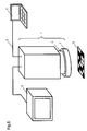
- a conventional two-dimensional code reader is shown in a block diagram in Fig. 10. Its appearance is given in Fig. 11.
- the conventional two-dimensional code reader was composed of a commercial video camera 100, and a signal processor 200 for processing the signals of the video camera 100.
- the video camera 100 is composed mainly of an image sensor 8 and an amplifier (not shown).
- the video camera 100 converts a reflected light from a code symbol 3 or its periphery into an electric signal, and sends the converted electric signal into the signal processor 200.
- the signal processor 200 is composed of an AD converter 9, signal storing means 10, a microprocessor 11, and a communication interface 12.
- the AD converter 9 converts the electric signal from the image sensor 8 of the video camera 100 into a digital signal.
- the signal storing means 10 stores the signal digitized by the AD converter 9.
- the microprocessor 11 recognizes the signal stored in the signal storing means 10.
- the microprocessor 11 transmits the result of the recognition process to a host system such as POS (point of sales) or PC (personal computer) through the communication interface 12.
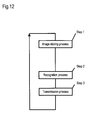
- Step 1 Image storing process
- the microprocessor 11 processes to store the output signal from the video camera 100 into the signal storing means 10 composed of a memory through the AD converter 9.
- step 1 After all output signals are stored at step 1, the microprocessor 11 recognizes them.
- Step 3 Transmission to host
- the result recognized at step 2 is transmitted by the microprocessor 11 to the host system such as POS or PC through the communication interface 12.
- the conventional optical information reader or optical information reading system also included a two-dimensional code reader of a type capable of displaying the code symbol and its periphery to be read, being photoelectrically converted by the video camera 100, as contrast (image) in the display unit.
- the conventional optical information reader or optical information reading system could not display the magnitude of electric signal (hereinafter called detecting intensity) photoelectrically converted by the video camera 100 as waveform or the like, and hence it was difficult to adjust the quantity of light received by the video camera 100 accurately.
- Focusing when manufacturing or installing was adjusted by viewing the display image.
- Such adjustment involved a problem of individual difference due to the individual sense. If set at the irradiation illuminance appropriate for the reading condition at the time of installation, it may be changed due to deterioration of light source in the course of time or effects of external light. Accordingly, in the conventional optical information reader or optical information reading system, it was impossible to obtain the reading condition stably including the optimum irradiation illuminance at the time of reading.
- the conventional two-dimensional code reader was composed of two sections as shown in Fig. 11, that is, the video camera and signal processor.
- the two sections are coupled through signal cables.
- Such conventional constitution was high in cost and complicated in handling.
- an object of the invention to present an optical information reader and an optical information reading system capable of:
- the optical information reader of the invention comprises:
- This microprocessor has a function of decoding the signal digitized by the AD converter into the information possessed by the code symbol.
- the optical information reader of the invention has all the constituent parts integrated into one body.
- Fig. 1 is a block diagram of a two-dimensional code reader 1 as an optical information reader in embodiment 1 of the invention.
- Fig. 2 shows its appearance.
- illuminating means 20 enclosed by broken line is composed of a light source 7 and an irradiation illuminance control circuit 21.
- the irradiation illuminance control circuit 21 is designed to adjust the brightness of the light source 7 by a command from a microprocessor 11.
- a line specifying unit 13 is to specify the line for picking up one of the digital signals stored in a signal storage unit 10.
- the microprocessor 11 picks up a signal of at least one line specified by the line specifying unit 13.
- the microprocessor 11 has a function of decoding the signal digitized by an AD converter 9 into the information possessed by the code symbol.
- a lens 2 shown in Fig. 2 is to adjust the focus of a code symbol 3 to an image sensor 8.
- the two-dimensional code reader 1 which is the optical information reader in embodiment 1 of the invention has the section corresponding to the conventional video camera, the section corresponding to the signal processor, and the irradiation illuminance control circuit 21 composed in one case.
- the light source 7 is formed as part of the two-dimensional code reader 1 as shown in Fig.2, but it may be also formed separately.
- Fig. 3 shows the flow of process of the optical information reader in embodiment 1 of the invention.
- the same parts as in Fig. 12 showing the flow of the prior art are identified with same reference numerals.
- Step 1 Image storing process
- the microprocessor 11 processes to store the output signal from the image sensor 8 into the signal storing means 10 composed of a memory through the AD converter 9.
- Step 10 Mode judgement
- the microprocessor 11 judges whether the mode (operation setting) is ordinary "reading” or ''waveform output.
- the operation is set by a switch (not shown) provided on the main body of the two-dimensional code reader 1, but it may be also set by communication with the host.
- the microprocessor 11 recognizes the digital signal stored in the signal storage unit 10.
- Step 3 Transmission to host
- the result recognized at step 2 is transmitted by the microprocessor 11 to the host system such as POS or PC as the image.
- the microprocessor 11 also decodes the recognized result into the information possessed by the code symbol, and sends the result to the host such as POS or PC.
- the microprocessor 11 picks up the data of the specified line.
- the specifying means may specify by the switch provided in the circuit board, specify by the communication with the host, or specify the line to be picked up by reading a specific two-dimensional code.
- Step 12 Display process
- the microprocessor 11 processes the data picked up at step 11 to be displayed in a waveform in the display unit such as CRT or liquid crystal device.
- the data processed for display is transmitted to the host such as POS or PC through the communication interface 12, and is displayed.
- the AD converter is one of a type of converting an analog signal into an eight-bit digital signal. Accordingly, the displayed data is displayed by the value of 0 to 255 as the detecting intensity on the axis of ordinates.
- the detecting intensity of the digital signal from the barcode as shown in the code symbol 3 in Fig. 4 displayed in waveform is schematically shown in Fig. 5.
- the axis of abscissas denotes the horizontal position of the image.
- the optical information reader of the invention can display the magnitude of electric signal (detecting intensity) photoelectrically converted by the image sensor 8 of the specified line accurately in waveform.
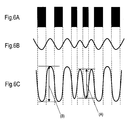
- Fig. 6A is a waveform diagram schematically showing the state of viewing the thin lines and thick lines of the code symbol, with the focus not adjusted.
- Fig. 6C is a waveform diagram schematically showing the state of viewing the thin lines and thick lines of the code symbol, with the focus adjusted. That is, this adjustment can be done easily and accurately by anyone.
- Fig. 7 is a block diagram of a two-dimensional code reader 1 which is an optical information reader in embodiment 2 of the invention.
- first signal storing means 14 stores the output signal from an image sensor 8 digitized by an AD converter 9 as a reference signal.
- the first signal storing means 14 is composed of a nonvolatile memory such as EEPROM or a memory supported by a battery, so that the stored data may not be lost if the power is cut off.
- Second signal storing means 15 is used in the recognition process at the time of ordinary reading.
- the gain control means 16 controls the gain of the output of the image sensor 8 according to the instruction from the microprocessor 11.
- the microprocessor 11 on the other hand, by the offset of the code symbol position, controls the contrast of the waveform showing the image. Further, the gain control means 16 and/or microprocessor 11 controls the detecting intensity by an electronic shutter which controls the CCD accumulated electric charge for composing the image sensor 8.
- the digital signal stored in the first signal storing means 14 and the digital signal stored in the second signal storing means 15 are compared by the microprocessor 11, and gain control means 16 or irradiation illuminance control circuit 21 is controlled by the microprocessor 11 so that the amplitude (A) of the detecting intensity of the thin lines or the amplitude (B) of the detecting intensity of the thick lines may be equal at the time of installation and at the time of adjustment, in the case of the image of the code symbol 3 composed of a plurality of black and white thin lines and thick lines as shown in Fig. 5.
- the irradiation illuminance is intensified and/or the gain control is raised, so that the reading condition including the optimum irradiation illuminance may be obtained for recognition process.
- Embodiment 3 relates to an optical information reading system employing the optical information reader in embodiments 1 and 2.
- a structural diagram of embodiment 3 is shown in Fig. 8.
- optical information reading system of embodiment 3 is composed of:
- the LED and buzzer for showing the reading result are not shown, but they may be either provided or not.
- the display means 5 is provided aside from the external control device 4, but the display unit furnished to the external control device 4 may be used instead.
- the image of the code symbol 3 may be displayed in the display means 5, and the waveform output may be displayed in the display unit of the external control device 4.
- Fig. 9 shows the flow of process of the optical information reading system of embodiment 3 of the invention.
- the same parts as in Fig. 3 showing the flow of the embodiment 1 are identified with same reference numerals.
- Step 1 Image storing process
- the microprocessor 11 requests to store the output signal from the image sensor 8 into the signal storing means 10 composed of a memory through the AD converter 9.
- Step 10 Mode judgement
- the microprocessor 11 judges whether the mode (operation setting) is ordinary “reading” or "waveform output.”
- Step 30 Signal pickup specification
- the microprocessor 11 specifies to pick up the signal from which line.
- the data showing the line specified at step 30 is transmitted by communication from the external control device 4 to the two-dimensional code reader 1.
- the two-dimensional code reader 1 receives the data showing the specified line from the external control device 4.
- the data showing the detecting intensity of the specified line is picked up.
- the data of the picked-up line is transmitted by communication to the external control device 4.
- the data of the picked-up line is received.
- the received data is displayed as waveform.
- step 10 if the mode is "reading" (Yes), the processing is same as in embodiment 1 shown in Fig. 3, and its illustration and explanation are omitted.
- the magnitude of the electric signal (detecting intensity) photoelectrically converted by the image sensor 8 can be accurately displayed in the external control device 4.
- the signal of at least one specified line can be picked up from the digital signals stored in the signal storing means, a desired line (for example, upper part, middle part, etc.) in the viewing field of the image sensor requested by the user can be selected, and the picked-up signal can be processed.
- a desired line for example, upper part, middle part, etc.
- the picked-up signal can be transformed into an image and shown in the display, it is easier to judge visually for the user.
- the quantity of light received by the image sensor can be adjusted accurately, so that it is easier to judge visually for the user.
- a desired arbitrary line can be selected from the external control device disposed at a place remote from the signal pickup means.
- the signal of a specified line can be transmitted to the external control device disposed at a place remote from the signal pickup means. As a result, the signal can be analyzed also in the external control device.
- the picked-up line can be displayed in the display unit also in the external control device disposed at a place remote from the signal pickup means.
- the reading condition including the optimum irradiation illuminance adjusted at the time of installation can be obtained.
- the invention is not limited to the two-dimensional code reader or the system using the same, but may be applied also in the one-dimensional barcode reader, OCR reader, hand-held terminal, or other portable information terminal for reading the information optically, and the system using the same.
Landscapes
- Physics & Mathematics (AREA)
- Engineering & Computer Science (AREA)
- Health & Medical Sciences (AREA)
- Electromagnetism (AREA)
- General Health & Medical Sciences (AREA)
- Toxicology (AREA)
- Artificial Intelligence (AREA)
- Computer Vision & Pattern Recognition (AREA)
- General Physics & Mathematics (AREA)
- Theoretical Computer Science (AREA)
- Facsimile Scanning Arrangements (AREA)
- Image Input (AREA)
Abstract
Description
Claims (11)
- An optical information reader comprising:an image sensor for taking in a reflected light from a code symbol and its periphery and converting into an electric signal,an AD converter for converting the electric signal from said image sensor into a digital signal,decoding means for decoding the signal digitized from the electric signal from said image sensor in order to restore the information possessed by said code symbol,signal storing means for storing the signal digitized from the electric signal from said image sensor, andsignal pickup means for picking up the signal of at least one specified line out of the digital signals stored in said signal storing means.
- The optical information reader of claim 1, which is accommodated in one case.
- The optical information reader of claim 1, wherein the signal picked up from the signal pickup means is transformed into an image and is displayed in the display unit.
- An optical information reading system comprising:an image sensor for taking in a reflected light from a code symbol and its periphery and converting into an electric signal,an AD converter for converting the electric signal from said image sensor into a digital signal,decoding means for decoding the signal digitized from the electric signal from said image sensor in order to restore the information possessed by said code symbol,signal storing means for storing the signal digitized from the electric signal from said image sensor, andsignal pickup means for picking up the signal of at least one specified line out of the digital signals stored in said signal storing means,
wherein each signal of said digital signals is related to the detecting intensity information, and the detecting intensity related to each signal is displayed as waveform. - The optical information reading system of claim 1, further comprising specifying means for specifying at least one arbitrary line in the nearly lateral direction and/or vertical direction out of the digital signals stored in the signal storing means.
- An optical information reading system comprising:an image sensor for taking in a reflected light from a code symbol and its periphery and converting into an electric signal,an AD converter for converting the electric signal from said image sensor into a digital signal,decoding means for decoding the signal digitized from the electric signal from said image sensor in order to restore the information possessed by said code symbol,signal storing means for storing the signal digitized from the electric signal from said image sensor, andsignal pickup means for picking up the signal of at least one specified line out of the digital signals stored in said signal storing means,
wherein said signal pickup means and an external control device are connected through a communication line, said external control device includes specifying means for specifying at least one arbitrary line in the nearly lateral direction and/or vertical direction out of the digital signals stored in said signal storing means, and the position information specified by said specifying means is transmitted to said signal pickup means through said communication line. - The optical information reading system of claim 6, wherein the signal of at least one line specified by the position information is transmitted to the external control device.
- The optical information reading system of claim 7, wherein the detecting intensity information about the data of at least one arbitrary line being picked up is displayed in the display unit.
- The optical information reading system of claim 4, further comprising illuminating means and/or gain control means for adjusting the detecting intensity information related to the digitized signal.
- An optical information reading system comprising:an image sensor for taking in a reflected light from a code symbol and its periphery and converting into an electric signal,an AD converter for converting the electric signal from said image sensor into a digital signal,decoding means for decoding the signal digitized from the electric signal from said image sensor in order to restore the information possessed by said code symbol, anda plurality of signal storing means for storing the signal digitized from the electric signal from said image sensor,
wherein said plurality of signal storing means includes first signal storing means for storing a digital signal as reference, and second signal storing means for storing the signal digitized at the time of reading, further comprising:illuminating means and/or gain control means for adjusting the detecting intensity information related to the signal digitized depending on the result of comparison by comparing the signal stored in the first signal storing means and the digital signal stored in the second signal storing means. - The optical information reading system of claim 10, wherein the gain control means is composed of electronic shutter control and/or offset control and/or gain control.
Applications Claiming Priority (2)
| Application Number | Priority Date | Filing Date | Title |
|---|---|---|---|
| JP2755999 | 1999-02-04 | ||
| JP2755999 | 1999-02-04 |
Publications (2)
| Publication Number | Publication Date |
|---|---|
| EP1026619A2 true EP1026619A2 (en) | 2000-08-09 |
| EP1026619A3 EP1026619A3 (en) | 2001-09-19 |
Family
ID=12224415
Family Applications (1)
| Application Number | Title | Priority Date | Filing Date |
|---|---|---|---|
| EP00300761A Withdrawn EP1026619A3 (en) | 1999-02-04 | 2000-02-01 | Optical information reader and optical information reading system |
Country Status (1)
| Country | Link |
|---|---|
| EP (1) | EP1026619A3 (en) |
Family Cites Families (7)
| Publication number | Priority date | Publication date | Assignee | Title |
|---|---|---|---|---|
| CA1129549A (en) * | 1978-09-18 | 1982-08-10 | Transaction Technology, Inc. | Adaptive threshold optical reader |
| CA1207902A (en) * | 1982-09-27 | 1986-07-15 | Nelson Friberg | High speed optical sensor |
| US4659939A (en) * | 1985-04-24 | 1987-04-21 | Pitney Bowes Inc. | Optical scanning system including an amplifier |
| US5235652A (en) * | 1988-02-09 | 1993-08-10 | Nally Robert B | Qualification system for printed images |
| KR100257128B1 (en) * | 1991-11-11 | 2000-05-15 | 시모야마 도시로 | Symbol information reading device |
| US5345089A (en) * | 1992-12-24 | 1994-09-06 | Pitney Bowes Inc. | System and method for optical scanner sensitivity adjustment |
| JPH07114630A (en) * | 1993-10-19 | 1995-05-02 | Matsushita Electric Ind Co Ltd | Small information terminal device with image processing function |
-
2000
- 2000-02-01 EP EP00300761A patent/EP1026619A3/en not_active Withdrawn
Also Published As
| Publication number | Publication date |
|---|---|
| EP1026619A3 (en) | 2001-09-19 |
Similar Documents
| Publication | Publication Date | Title |
|---|---|---|
| US20230087928A1 (en) | Indicia reader for size-limited applications | |
| US7025272B2 (en) | System and method for auto focusing an optical code reader | |
| US9183425B2 (en) | Image sensor pixel array having output response curve including logarithmic pattern for image sensor based terminal | |
| US6654062B1 (en) | Electronic camera | |
| US5703349A (en) | Portable data collection device with two dimensional imaging assembly | |
| US6657673B2 (en) | Method and apparatus for detecting and recording images | |
| EP2444917A1 (en) | Autofocusing optical imaging device | |
| US20090034951A1 (en) | Remote photographing system | |
| US6775077B1 (en) | Micro reader scan engine with prism | |
| JP2002027047A (en) | Portable information terminal equipment | |
| US20020075563A1 (en) | Camera for microscope and microscope system | |
| US7310113B2 (en) | Camera for automatically adjusting image brightness for an image on a display | |
| EP1723580B1 (en) | Image pickup apparatus, electronic tag reading apparatus, and program | |
| KR101571334B1 (en) | Apparatus for processing digital image and method for controlling thereof | |
| EP1026619A2 (en) | Optical information reader and optical information reading system | |
| JP3495410B2 (en) | Data symbol reading device | |
| US20050134706A1 (en) | Mobile communication terminal equipped with camera and method of controlling the same | |
| JP2005303400A (en) | Imaging device, image processing device, illumination light source, and illumination device | |
| JPH11345278A (en) | Bar code reader and bar code reading method | |
| JP3309842B2 (en) | Optical information reading device and optical information reading system | |
| JPH07262302A (en) | Data symbol reader | |
| KR101427658B1 (en) | Apparatus for processing digital image and method for controlling thereof | |
| US6967679B2 (en) | Imaging apparatus, imaging optical unit, and imaging system | |
| KR20110029004A (en) | Digital imaging media, control methods thereof, and computer-readable media | |
| KR101495081B1 (en) | Tag Information Retrieval System for Image Images Using RFID |
Legal Events
| Date | Code | Title | Description |
|---|---|---|---|
| PUAI | Public reference made under article 153(3) epc to a published international application that has entered the european phase |
Free format text: ORIGINAL CODE: 0009012 |
|
| AK | Designated contracting states |
Kind code of ref document: A2 Designated state(s): AT BE CH CY DE DK ES FI FR GB GR IE IT LI LU MC NL PT SE Kind code of ref document: A2 Designated state(s): DE FR GB IT |
|
| AX | Request for extension of the european patent |
Free format text: AL;LT;LV;MK;RO;SI |
|
| PUAL | Search report despatched |
Free format text: ORIGINAL CODE: 0009013 |
|
| AK | Designated contracting states |
Kind code of ref document: A3 Designated state(s): AT BE CH CY DE DK ES FI FR GB GR IE IT LI LU MC NL PT SE |
|
| AX | Request for extension of the european patent |
Free format text: AL;LT;LV;MK;RO;SI |
|
| RAP1 | Party data changed (applicant data changed or rights of an application transferred) |
Owner name: MATSUSHITA ELECTRIC INDUSTRIAL CO., LTD. |
|
| 17P | Request for examination filed |
Effective date: 20020201 |
|
| AKX | Designation fees paid |
Free format text: DE FR GB IT |
|
| 17Q | First examination report despatched |
Effective date: 20070604 |
|
| STAA | Information on the status of an ep patent application or granted ep patent |
Free format text: STATUS: THE APPLICATION IS DEEMED TO BE WITHDRAWN |
|
| 18D | Application deemed to be withdrawn |
Effective date: 20071016 |