RELATED APPLICATION
This application is related to U.S. application serial No. 09/244,137
(Attorney Docket No. 06502-0222-00000), entitled "Method, Apparatus, and
Article of Manufacture for Developing and Executing Data Flow Programs,"
which is incorporated in its entirety herein by reference.
BACKGROUND OF THE INVENTION
A. Field of the Invention
This invention relates to the field of multiprocessor computer systems and,
more particularly, to data driven processing of computer programs using a
multiprocessor computer system.
B. Description of the Related Art
Multiprocessor computer systems include two or more processors that may be
employed to execute the various instructions of a computer program. A particular
set of instructions may be performed by one processor while other processors
perform unrelated sets of instructions.
Fast computer systems, like multiprocessor computer systems, have stimulated
the rapid growth of a new way of performing scientific research. The broad
classical branches of theoretical science and experimental science have been
joined by computational science. Computational scientists simulate on
supercomputers phenomena too complex to be reliably predicted by theory and
too dangerous or expensive to be reproduced in a laboratory. Successes in
computational science have caused demand for supercomputing resources to rise
sharply in recent years.
During this time, multiprocessor computer systems, also referred to as "parallel
computers," have evolved from experimental contraptions in laboratories to become the
everyday tools of computational scientists who need the ultimate in computing resources
in order to solve their problems. Several factors have stimulated this evolution. It is not
only that the speed of light and the effectiveness of heat dissipation impose physical
limits on the speed of a single processor. It is also that the cost of advanced single-processor
computers increases more rapidly than their power. And price/performance
ratios become more favorable if the required computational power can be found from
existing resources instead of purchased. This factor has caused many sites to use existing
workstation networks, originally purchased to do modest computational chores, as
"SCAN"s (SuperComputers At Night) by utilizing the workstation network as a parallel
computer. This scheme has proven so successful, and the cost effectiveness of individual
workstations has increased so rapidly, that networks of workstations have been purchased
to be dedicated to parallel jobs that used to run on more expensive supercomputers. Thus,
considerations of both peak performance and price/performance are pushing large-scale
computing in the direction of parallelism. Despite these advances, parallel computing has
not yet achieved wide-spread adoption.
The biggest obstacle to the adoption of parallel computing and its benefits in economy
and power is the problem of inadequate software. The developer of a program
implementing a parallel algorithm for an important computational science problem may
find the current software environment to be more of an obstruction than smoothing the
path to use of the very capable, cost-effective hardware available. This is because
computer programmers generally follow a "control flow" model when developing
programs, including programs for execution by multiprocessor computers systems.
According to this model, the computer executes a program's instructions sequentially (i.e.,
in a series from the first instruction to the last instruction) as controlled by a program
counter. Although this approach tends to simplify the program development process, it is
inherently slow.
For example, when the program counter reaches a particular instruction in a program
that requires the result of another instruction or set of instructions, the particular
instruction is said to be "dependent" on the result and the processor cannot execute that
instruction until the result is available. Moreover, executing programs developed under
the control flow model on multiprocessing computer systems results in a significant waste
of resources because of these dependencies. For example, a first processor executing one
set of instructions in the control flow program may have to wait for some time until a
second processor completes execution of another set of instructions, the result of which is
required by the first processor to perform its set of instructions. This wait-time translates
into an unacceptable waste of computing resources in that at least one of the processors in
this two-processor configuration is idle the whole time while the program is running.
To better exploit parallelism in a program some scientists have suggested use of a
"data flow" model in place of the control flow model. The basic concept of the data flow
model is to enable the execution of an instruction whenever its required operands become
available, and thus, no program counters are needed in data-driven computations.
Instruction initiation depends on data availability, independent of the physical location of
an instruction in the program. In other words, instructions in a program are not ordered.
The execution simply follows the data dependency constraints.
Programs for data-driven computations can be represented by data flow graphs. An
example data flow graph is illustrated in Fig. 1 for the calculation of the following
expression:
z = (x + y) * 2
When, for example, x is 5 and y is 3, the result z is 16. As shown graphical in the figure, z
is dependent on the result of the sum x and y . The data flow graph is a directed
acyclic graph ("DAG") whose nodes correspond to operators and arcs are pointers for
forwarding data. The graph demonstrates sequencing constraints (i.e., constraints with
data dependencies) among instructions.
For example, in a conventional computer, program analysis is often done (i) when a
program is compiled to yield better resource utilization and code optimization, and (ii) at
run time to reveal concurrent arithmetic logic activities for higher system throughput. For
instance, consider the following sequence of instructions:
The following five computational sequences of these instructions are permissible to
guarantee the integrity of the result when executing the instructions on a serial computing
system (e.g., a uniprocessor system):
- 1, 2, 3, 4, 5, 6
- 1, 3, 2, 5, 4, 6
- 1, 3, 5, 2, 4, 6
- 1, 2, 3, 5, 4, 6
- 1, 3, 2, 4, 5, 6
For example, the first instruction must be executed first, but the second or third
instruction can be executed second, because the result of the first instruction is required
for either the second or third instruction, but neither the second nor the third requires the
result of the other. The remainder of each sequence follows this simple rule-no
instruction can be run until its operands (or inputs) are available.
In a multiprocessor computer system with two processors, however, it is possible to
perform the six operations in four steps (instead of six) with the first processor computing
step 1, followed by both processors simultaneously computing steps 2 and 3, followed by
both processors simultaneously steps 4 and 5, and finally either processor computing step
6. This is an obvious improvement over the uniprocessor approach because execution
time is reduced.
Using data flow as a method of parallelization will thus extract the maximum amount
of parallelism from a system. Most source code, however, is in a control form, which is
difficult and clumsy to parallelize efficiently for all types of problems.
It is therefore desirable to provide a facility for developers to more easily develop data
flow programs and to convert existing control flow programs into data flow programs for
execution on multiprocessor computer systems. There is also a need for technique that
optimizes performance of the data flow programs in a multiprocessor computer system.
SUMMARY OF THE INVENTION
Methods, systems, and articles of manufacture consistent with the present invention
overcome the shortcomings of existing systems by enabling developers to easily convert
control flow programs into a data flow approach and to develop new programs according
to the data flow model. According to one aspect of the present invention, such methods,
systems, and articles of manufacture, as embodied and broadly described herein, this
program development process includes defining a memory region and dividing it into
multiple blocks, each block defining a set of values associated with a function. Sets of the
blocks are defined, each block in a set having a state reflected by a designated portion of
the program that when executed transforms the values forming the block based on the
function. Additionally, any dependencies among the blocks are specified by the user.
Each dependency indicates a relationship between two blocks and requires the portion of
the program associated with one of the two blocks to be executed before the portion of the
program associated with the other block.
In accordance with another aspect of the present invention, methods, systems, and
articles of manufacture, as embodied and broadly described herein, execute a data flow
program in a multiprocessor computer system. Execution of the program involves
selecting information in a queue identifying a block formed of a set of values associated
with a function of the program and determining whether execution of a portion of the
program associated with the selected block is dependent on a result of the execution of a
portion of the program associated with another block. The portion of the program
associated with the selected block is then executed when it is determined that execution of
the portion of the program associated with the selected block is not dependent on a result
of the execution of a portion of the program associated with the other block. This
selection and determination is repeated when it is determined that execution of the portion
of the program associated with the selected block is dependent on a result of the execution
of a portion of the program associated with the other block.
In accordance with yet another aspect of the present invention, methods, systems, and
articles of manufacture are provided that optimize execution of data flow programs in a
multiprocessor computer system. A data flow program consists of memory region
information, including block information and dependency information. The block
information reflects multiple blocks that define a memory region. Each block is formed
of a set of values associated with a function and has a state reflected by a designated
portion of the program that when executed transforms the values forming the block based
on the function. The dependency information reflects any dependencies among the
blocks, each dependency indicating a relationship between two blocks and requiring the
portion of the program associated with a first block of the relationship to be executed
before the portion of the program associated with a second block of the relationship. A
queue is formed organizing the memory region information in such a way as to optimize
execution of data flow program.
In accordance with one aspect of the invention, as broadly described herein, the queue
is formed by generating a directed acyclic graph based on the memory region information
with each block having a corresponding node in the graph, traversing the directed acyclic
graph according to a predetermined function, and placing information identifying each
block in the queue based on the traversal of the directed acyclic graph. In accordance
with another aspect of the invention, as broadly described herein, the queue may be
divided into part, or multiple queues may be employed. In this case, each part of the
queue or individual queue has a priority, and (i) the blocks are assigned to the parts or
queues based on a priority associated with each block and (ii) selected from the parts or
queues for execution in accordance with the queue assignment.
BRIEF DESCRIPTION OF THE DRAWINGS
The accompanying drawings, which are incorporated in and constitute a part of this
specification, illustrate an implementation of the invention and, together with the
description, serve to explain the advantages and principles of the invention. In the
drawings,
DETAILED DESCRIPTION
Reference will now be made in detail to an implementation consistent with the present
invention as illustrated in the accompanying drawings. Wherever possible, the same
reference numbers will be used throughout the drawings and the following description to
refer to the same or like parts.
Introduction
Methods, systems, and articles of manufacture consistent with the present invention
enable developers to convert control flow programs into data flow programs and to
develop new programs according to the data flow model. Such methods, systems, and
articles of manufacture may utilize a development tool, including a computer-human
interface, to design and develop the data flow programs.
Data flow programs developed in accordance with the principles of the present
invention are executed on a multiprocessor computer system using a data flow model.
The interface may be operated on a different data processing system from that used for
program execution. Alternatively, the interface may be operated on the same system used
for program execution.
One characteristic of the data flow model in accordance with the present invention is
that operations can be performed in parallel on blocks of a memory region. A block
consists of a set of data, such as an array or matrix of values or other information.
Together, multiple blocks form a memory region.
The data flow program development tool provides an interface that enables a
developer to define a memory region containing data associated with a system. In this
context, the term "system" refers to a physical, mathematical, or computational problem,
such as the structural analysis of a building, the flow of fluid through a pipe, etc.
Typically, such complex systems require a great deal of processing to solve many
equations and the result of one set of equations is dependent on the result of another set of
equations. For example, fluid flowing though a pipe is slowed by friction from the
interior of the pipe. The friction directly affects the speed of the fluid touching the
interior of the pipe (defined by a first set of equations) and indirectly affects other fluid in
the pipe not touching the interior (defined perhaps by the same equations but dependent
on the result of the first set of equations). Thus, the effects of friction caused by the
interior of the pipe are different for fluid flowing in the pipe depending on where in the
fluid is in the pipe at any given instance.
After defining the region, the developer then divides the region into blocks, and for
each block, the developer specifies the program code to be executed on the values within
the block as well as any dependency between the block and other blocks in the region.
Blocks with the same program code are said to share the same "state." They can generally
be executed in parallel because they do not depend on one another for results. In the fluid
flow example, blocks associated with fluid flowing next to the interior of the pipe would
share the same state (and therefore have the same program code for execution) but this
state (and code) would be different from the state (and code) of fluid that is not touching
the interior but is next to the fluid that is. Moving inwardly into the pipe and the state
(and code) of each block associated with fluid in the pipe changes to reflect the
dependencies in a similar manner.
Dependencies are reflected in links between each of the dependent blocks and the
blocks from which they depend. A block is dependent on another block when the first
block requires the result of the second block for the first block to perform properly within
the system. These relationships may be viewed graphically through a directed acyclic
graph ("DAG"). Associated with each node in the graph are program code and data
determined by the block.
The blocks are then queued for processing in a multiprocessor computer system.
Actually, the blocks themselves are not put in the queue. Rather, information identifying
each block such as a pointer is placed in the queue. The blocks are queued or organized
in the queue in a particular manner and the thread(s) executing the data flow program can
select the appropriate block for execution of its corresponding program code at any given
point in time during the data flow program execution. In one implementation, the blocks
are queued according to the dependency information associated with each block.
This block queuing process for performance optimization of the program follows the
organization of the DAG. In other words, the DAG may be logically traversed using a
number of different methods to select the best organization for the queue prior to program
execution. Moreover, the organization of the queue may be modified during program
execution to address factors affecting performance of the program not readily
determinable before program execution.
One approach to organizing the blocks involves traversing the DAG associated with a
memory region of blocks while applying a particular function, such as a weighting
function that assigns weights to each node or a sort algorithm applicable to DAGs. To
optimize performance of the data flow program, however, multiple queues may be
employed with each queue having a priority defining the order in which blocks are
dequeued. In other words, blocks in a higher priority queue are selected for execution
before blocks in another queue based on the priorities associated with the queues.
The developer may designate the number of threads available to process the blocks.
Each thread maintains a program counter and temporary memory, as needed, to perform
the program code associated with the blocks. For example, the developer may designate
one thread per processor. Alternative configurations are also possible in accordance with
the principles of the present invention.
Each thread, in turn, selects a block from the queue and executes the program code
designated by the developer for that block. As long as there are blocks in the queue, the
threads, when available, select them and execute their program code. Additionally,
queued blocks are selected for execution in a manner that reflects each block's
dependency information. When an available thread selects a queued block for execution,
the thread first examines the block's dependency information (i.e., any links to other
blocks) and if the blocks from which the selected block depends have completed
execution, then the thread can proceed to execute the program code for the selected block.
Otherwise, the tread may enter a wait state until it can begin executing the program code
for the selected block. Alternatively, the tread may select the next available block in the
queue, based on any priority if appropriate, and examine that block to determine its status
with respect to any blocks upon which it depends (i.e., have all blocks from which it
depends completed execution so that the program code of the selected block can be
executed safely). This process continues until the threads have completed executing the
program code associated with all blocks in the queue.
The following description includes details on the design and development of data flow
programs followed by aspects of the execution phase.
Defining a Data Flow Program Using Regions and Blocks
At the beginning of the design and development process, a developer specifies a
memory region and divides the region into blocks. This may be done graphically using an
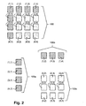
interface provided with the development tool. Figure 2 shows an example of a memory
region 100 that contains sixteen blocks arranged in a four-by-four matrix, with each block
identified by a row number and column number. For example, the block in the upper left
corner of memory region 100 is labeled (1,1) indicating that it is located in the first row
and the first column, and the block in the lower right hand corner of region 100 is labeled
(4,4) indicating that it is located in the lower right corner. All of the remaining fourteen
blocks follow the same labeling convention. As explained, each block contains a data set,
such as a matrix or array of values or information, to be processed in accordance with
certain program code.
After defining the memory region and dividing it into blocks, the developer specifies a
state of each block. As explained, the state of a block corresponds to the program code
that the developer assigns to that block, meaning that the developer intends to have the
multiprocessor computer system operate on the data in the block using the specified
program code. The interface provides the developer with a window or other facility to
provide the program code for a block. The development tool associates the code with its
block.
In the example region 100, the group of blocks 100a labeled (1,1), (2,1), (3,1), and
(4,1) share the same state, the group of blocks 100b labeled (1,2), (1,3), and (1,4) share
the same state, and the group of blocks 100c labeled (2,2), (2,3), (2,4), (3,2), (3,3), (3,4),
(4,2), (4,3), and (4,4) share the same state. The three different states are shown in Fig. 2
by different shading (or fill) for the blocks in each group.
Although the region 100 and its blocks are shown as being uniform in size, in practice
a memory region and blocks may have different shapes and sizes. For example, memory
region 100 consists of sixteen blocks in a four-by-four matrix and, although not specified
in the figure, each block may have an eight-by-eight matrix. Alternatively, and depending
on the application, the memory region may consist of a four-by-three matrix of blocks
and each block may consist of a three-by-two matrix of data.
Next, the developer specifies any dependency relationships among the blocks. Again,
a dependency relationship is defined as a relationship in which one block is dependent
upon the result or final state of another block during program execution. In other words,
one block has to be processed before the second, dependent block can be processed.
Figures 3A and 3B illustrate a number of examples of dependency relationships using
region 100 of Fig. 2. As shown in Fig. 3A, each of the blocks labeled (1,2), (1,3), and
(1,4) are dependent on the blocks labeled (1,1), (2,1), (3,1), and (4,1). This means that all
of the blocks labeled (1,1), (2,1), (3,1), and (4,1) must be processed before any of the
blocks (1,2), (1,3), and (1,4).
Similarly, Fig. 3B illustrates dependencies among each of the blocks labeled (1,2),
(1,3), and (1,4) and the blocks labeled (2,2), (2,3), (2,4), (3,2), (3,3), (3,4), (4,2), (4,3), and
(4,4). As shown, the block labeled (1,2) must be processed before the blocks in the same
column labeled (2,2), (2,3), (2,4); the block labeled (1,3) must be processed before the
blocks in the same column labeled (3,2), (3,3), (3,4); and the block labeled (1,4) must be
processed before the blocks in the same column labeled (4,2), (4,3), and (4,4). The
figures simply illustrate one example of a dependency configuration for memory region
100; other configurations may be selected by the developer.
To complete the view of dependency relationships, it is useful to see them graphically
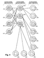
which can also be done using the user interface. Figure 4 is a DAG illustrating the
dependency relationships shown in Figs. 3a and 3b. The DAG of Fig. 4 illustrates
graphically that the output of all of the blocks sharing the first state are required for
processing by each of the blocks sharing the second state. In turn, each of the blocks
sharing the second state must be processed before each of the three groups of three blocks
that share the third state are processed. Such a graph may be used to order the blocks for
processing in accordance with the principles of the present invention (discussed below).
Data Flow Program Development Tool
Computer Architecture
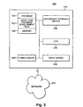
Figure 5 depicts an exemplary data processing system 500 suitable for practicing
methods and implementing systems consistent with the present invention. Data
processing system 500 includes a computer system 510 connected to a network 570, such
as a Local Area Network, Wide Area Network, or the Internet.
Computer system 510 contains a main memory 520, a secondary storage device 530, a
central processing unit (CPU) 540, an input device 550, and a video display 560. Main
memory 520 contains a data flow program development tool 522 and program 524. Data
flow program development tool 522 provides the interface for designing and developing
data flow programs, including programs that utilize control flow program code. Using
display 560 the tool enables developers to design memory regions, such as region 100 of
Fig. 2, and divide the regions into blocks with corresponding states. The tool further
enables developers to write program code to operate on each of the blocks using a
multiprocessor computer system (see Fig. 7).
Program 524 represents a data flow program designed in accordance with the present
invention, for example, using tool 522. Program 524 consists of the information
specifying a memory region, the blocks of the region, the program code associated with
each block, and any dependency relationships between the blocks.
Although aspects of one implementation are depicted as being stored in memory 520,
one skilled in the art will appreciate that all or part of systems and methods consistent
with the present invention may be stored on or read from other computer-readable media,
such as secondary storage devices, like hard disks, floppy disks, and CD-ROM; a carrier
wave received from a network such as the Internet; or other forms of ROM or RAM.
Finally, although specific components of data processing system 500 have been described,
one skilled in the art will appreciate that a data processing system suitable for use with
methods and systems consistent with the present invention may contain additional or
different components.
Process
Figure 6 is a flow chart of the process 600 performed by developers to write programs
using the data flow model. This process may be performed by tool 522 in a manner
consistent with the principles of the present invention. As explained, tool 522 provides an
environment, including a user interface and related functionality, for software developers
to write programs using the data flow model.
After a developer initiates execution of tool 522, it displays the various views
necessary for the developer to write a data flow program. First, the tool displays a view
with which the developer defines a memory region (step 610). Using tool 522, the
developer then divides the region into blocks (step 620).
As long as there are blocks in a region to be processed (step 630), the developer
selects a block (step 640), identifies any other block(s) that influence the selected block's
final state (in other words, block(s) upon which the selected block is dependent) (step
650), and specifies the program code for each block, for example, a portion of an existing
control flow program (step 660). Although this description involves converting an
existing control flow program for operation in a multiprocessor computer system using a
data flow organization, those skilled in the art will recognize that the tool 522 may also be
used to develop new data flow programs for execution on a multiprocessor computer
system.
After all of the blocks have been processed (steps 640 to 660), the developer
establishes the dependency relationships among the blocks by graphically linking them
together (step 670). The tool 522 uses the graphical information to generate and store
data reflecting the links. The blocks are then logically queued for processing in a
multiprocessor computer system (step 680). The tool 522 uses the dependency/link
information to queue the blocks in manner that reflects an appropriate order for
processing. For example, any block(s) upon which a particular block is dependent may be
placed in the queue before that particular block. For the example of Figs. 2-4, the blocks
may be queued in the manner shown in Fig. 7 with the blocks sharing the first state, i.e.,
(1,1), (2,1), (3,1), and (4,1), queued before the blocks with the second state, i.e., (1,2),
(1,3), and (1,4), and followed by the blocks sharing the third state, i.e., (2,2), (2,3), (2,4),
(3,2), (3,3), (3,4), (4,2), (4,3), and (4,4).
Multiprocessor Program Execution
As explained, in accordance with the present invention a data flow program is
executed in a multiprocessor computer system. There are many configurations for such a
multiprocessor computer system, one of which is illustrated in Fig. 8. For example, in a
tightly coupled configuration, the multiple processors of a system may all be located in
the same physical box. In an alternative, loosely coupled arrangement the system may be
formed by multiple computers in a network, each computer having a separate processor.
Multiprocessor Computer System
As shown in Fig. 8, a multiprocessor computer system 810 is connected to a network
interface 820, which enables a developer to transfer the data flow program from the
development tool environment (e.g., Fig. 5) for execution in multiprocessor computer
system 810. Alternatively, the data flow program development process in accordance
with the principles of the present invention may be performed on system 810, which is
also used for program execution. This alternative approach eliminates the need to transfer
the program from a system used for development to a separate system used for program
execution.
Multiprocessor computer system 810 comprises a single, shared memory 830 and
multiple processors 840a, 840b, . . . 840n. The number and type of processors is not
critical to execution of the data flow program developed in accordance with the present
invention. For example, an HPC Server with a multiple processor configuration may be
used. The HPC Server is a product of Sun Microsystems, Inc. Processes execute
independently on each of the processors and share memory 830. A process in this context
may be a thread controlling execution of program code associated with a block of a data
flow program developed using tool 522.
Process
The operation of a data flow program in accordance with the present invention will
now be described with reference to process 900 of Fig. 9. Multiple threads are used to
process the various components of a data flow program. Those skilled in the art will
recognize that the number of threads is not important; the developer may specify any
number, for example, one thread per processor, or the system may determine the number
of threads based on the number of available processors and an analysis of the data flow
program.
If a thread is available to process a block in accordance with its specified program
code (step 910), the thread determines whether there are any blocks in the queue (step
920). If so, the available thread selects a block from the queue for processing (step 930).
Typically, the blocks are selected from the queue based on the order in which they were
placed in the queue. If, however, a thread determines that a selected block is dependent
upon the execution of program code with respect to other block(s) that has/have not been
executed (step 940), the thread skips the selected block (step 950). Otherwise, any block
dependencies have been satisfied (step 940) and the thread uses an assigned processor to
execute the program code associated with the block (step 960). Once the thread(s)
processing a data flow program have dequeued all of the blocks in a queue awaiting
processing (step 920), the process ends.
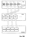
For purposes of illustrating the data flow program execution in accordance with
process 900, Figs. 10a-c illustrate a portion of the queue of Fig. 7, including the first five
blocks of region 100 queued for processing. As shown in Fig. 10a, each thread processes
a selected block using one of the processors. In this example, there are four threads and
four processors. When a thread completes processing, as shown for example in Fig. 10b
with one of the threads completing program execution of the block labeled (1,1), the
thread attempts to execute the next available thread in the queue, in this case, the block
labeled (1,2). However, the block labeled (1,2) is dependent upon the final state of other
blocks still being executed, namely, blocks (2,1), (3,1), and (4,1). Once execution of the
program code for all of these blocks has completed, as shown in Fig. 10c, a thread can
continue processing with block (1,2). Those skilled in the art will recognize that, as
opposed to remaining idle and, thus, not using computing resources efficiently, a thread
may skip processing blocks in the queue and continue to process other queued blocks
depending upon the dependency relationships associated with each block in the queue.
Also, although Fig. 10 shows four threads and four processors, more or fewer threads or
processors may be used depending upon the particular system configuration.
Optimizing Execution of Data Flow Programs
Once a DAG has been produced that represents the data dependencies for a given data
flow program, the program may be executed in a multiprocessor computer system by
traversing the DAG to order the nodes (i.e., blocks and corresponding program code) in
the queue(s) for execution. For a given DAG there are multiple traversals that allow all
the data dependencies for each node to be satisfied before that node is processed.
Different traversals will result in different performance especially when the DAG is
traversed in parallel with multiple threads of execution.
The principle factor in performance is the amount of time that a thread spends waiting.
This occurs when there is no node in the graph that has its dependencies satisfied. A
thread must therefore wait until processing of dependent blocks is complete before it can
start processing. There are two strategies to improve performance: (1) Using a traversal
that minimizes the wait time. (2) While a thread waits gather the resources needed to
process a node.
Minimizing Wait Time
There are two main techniques used to produce a traversal. The first is to act directly
upon the graph and reorder the nodes in a queue in the linear order that they will be
processed. The second involves placing the nodes in priority queues.
Fig. 11 is a flow chart of a process 1100 performed to organize blocks in queue(s) to
optimize performance of a data flow program in accordance with the present invention.
Process 1100 may be used for step 680 of process 600 to optimize performance of a data
flow program developed using tool 522. Also, the performance of any data flow program
with the requisite information may be optimized using process 1100. Process 1100 begins
with steps for receiving the block information and any related dependency information for
a data flow program (steps 1110 and 1120). A DAG is then generated reflecting the block
and dependency information (step 1130). A selected function is then applied when
traversing the DAG to optimize program execution by organizing the blocks in queue(s)
according to the function (step 1140).
One function involves computing a weight for each node and sorting the nodes based
upon the weights. The weights must be assigned such that no node has a data dependency
on a node that has a lesser weight. A violation of this rule could lead to a deadlock during
processing.
One weighting function involves assigning weights to nodes based on the maximum
number of nodes that can be traversed from a given node to any other node in the DAG.
For the example DAG shown in Fig. 12, a breadth-first traversal produces the following
order:
This is the order in which the nodes would be queued for processing. Assuming that each
node takes exactly one time-step to process, two threads can traverse the DAG in six time
steps as shown in the following table:
| Threads | Nodes Processed at Time |
| 1 | A | B | D | F | G | H |
| 2 | | C | E |
Using the weighting function where the maximum number of nodes that can be traversed
from a given node to any other node in the DAG is assigned as the weight for each node,
the following weights would be assigned to each node:
Consequently, sorting the nodes by weight would produce the following traversal,
i.e.,
order in which corresponding blocks would be queued of Fig. 12:
Two threads can execute code for the blocks queued according to this weighting function
in five time steps as follows:
| Threads | Node Processed at Time |
| 1 | A | C | E | G | H |
| 2 | | D | F | B |
Another weighting function involves assigning a time to each node that is an estimate
of the time it takes to process the node. The function could be the maximum sum
computed by adding up the times in each node along a traversal to another node in the
DAG. Another modification is to assign a priority to each process (i.e., operation
performed by the program code associated with each node). In the case where the
weighting function produces a tie, the priority of the process associated with the node
determines which node is processed first.
A sorting function may also be used to optimize program performance. Given a
number,
n , the sort can try to produce a DAG with a width of
n . First, all the nodes with
no unsatisfied dependencies are identified. Then the nodes with the largest weight are
placed on the list. All data dependencies for the nodes on the list are considered satisfied
and the algorithm is repeated until the entire DAG has been traversed. For example, using
the DAG shown in Fig. 13, a simple sort would produce the following traversal:
This traversal would take six time steps with two threads to complete:
| Threads | Nodes Processed at Time |
| 1 | A | B | D | F | G | H |
| 2 | | C | E |
However, a width-based sort with an
n of 2 would produce the following traversal:
This traversal can produce an order in which two threads can complete execution in five
time steps as follows:
| Threads | Node Processed at Time |
| 1 | A | B | D | E | H |
| 2 | | C | F | G |
Accordingly, any ordering function that assigns a weight to a first node to be executed that
is greater than a dependent node should produce a useful traversal and, thus, queue order
for execution that optimizes the program's overall performance.
Another optimization function uses multiple queues, each with a different priority
such that the threads select blocks out of the queues according to the queue priorities.
Alternatively, a single queue may be used for this purpose and divided into different parts,
each part having a different priority. To use this optimization approach, a priority must be
assigned to each node in the graph. One method involves assigning high priorities to
nodes that are associated with "bottlenecks", i.e., slow overall execution of a node's
program code because, for example, it requires a significant amount of input and/or output
operations.
For example, the DAG illustrated in Fig. 14 has nodes associated with three processes
A, B, and C. In this example, the process A nodes should be given a higher priority.
Assuming that process A is given a priority of level of "2" and B and C are given a
priority level of "1" then the nodes would be placed in two queues as follows:
At the time of execution, each thread checks the first node in
queue 2. If the node's
dependencies have been satisfied, it is removed from the queue and processed. If not, the
thread checks for a node in
queue 1. If no nodes can be found it repeats the process until
a node becomes available.
Assuming that each process takes one time step, two threads would execute the nodes
as follows:
| Threads | Node Processed at Time |
| 1 | A1 | A2 | A3 | B2 | B3 | |
| 2 | | B1 | C1 | C2 | C3 |
Using three threads, performance would be improved by one time step as follows:
| Threads | Node Processed at Time |
| 1 | A1 | A2 | A3 | B3 | |
| 2 | | B1 | B2 | C3 | |
| 3 | | C1 | C2 |
Thus, the same DAG can produce different traversals depending on a number of factors,
including the number of threads available for program execution. Two threads produces
the following traversal: A1 A2 B1 A3 C1 B2 C2 B3 C3. Three threads produces the
following traversal: A1 A2 B1 C1 A3 B2 C2 B3 C3.
Allocating Resources While Waiting
Although not all of the wait time associated with program execution can be
eliminated, the spent waiting can be put to use by pre-fetching data that a thread will need
during execution. First it identifies a node whose dependencies will likely be satisfied
shortly and while it is waiting for the node to become available (i.e., its dependencies
become fully satisfied) it pre-fetches the data it will need to process that node. When the
dependencies are satisfied then processing can porceed at a higher rate, since some of the
data is in cache.
Conclusion
Methods systems, and articles of manufacture consistent with the present invention
thus enable developer to easily develop data flow programs and to convert existing
control flow programs according to the data flow model. By permitting developers to
define memory regions and divide them into blocks with corresponding states (each
related to particular control flow program instructions), the interface facilitates the
development of a data flow program for execution in a multiprocessor environment.
Although components of the program utilize the control flow programming method, the
program as a whole is designed using a data flow approach. Additionally, each block
contains a set of data, meaning that the program code associated with each block does not
necessarily operate on scalars or single data items. This makes the present approach more
useful for data-intensive programming systems that require significant data processing in
which components can be easily processed in parallel on a multiprocessor computer
system.
Also, methods consistent with the present invention are applicable to all programs for
execution in a multiprocessor system regardless of the computer programming language.
For example, Fortran 77 is a programming language commonly used to develop programs
for execution by multiprocessor computer systems.
The foregoing description of an implementation of the invention has been presented
for purposes of illustration and description. It is not exhaustive and does not limit the
invention to the precise form disclosed. Modifications and variations are possible in light
of the above teachings or may be acquired from practicing of the invention. For example,
the described implementation includes software but the present invention may be
implemented as a combination of hardware and software or in hardware alone. The
invention may be implemented with both object-oriented and non-object-oriented
programming systems. The scope of the invention is defined by the claims and their
equivalents.