EP1026397A2 - Control valve in variable displacement compressor - Google Patents
Control valve in variable displacement compressor Download PDFInfo
- Publication number
- EP1026397A2 EP1026397A2 EP00101853A EP00101853A EP1026397A2 EP 1026397 A2 EP1026397 A2 EP 1026397A2 EP 00101853 A EP00101853 A EP 00101853A EP 00101853 A EP00101853 A EP 00101853A EP 1026397 A2 EP1026397 A2 EP 1026397A2
- Authority
- EP
- European Patent Office
- Prior art keywords
- value
- control valve
- valve body
- current
- compressor
- Prior art date
- Legal status (The legal status is an assumption and is not a legal conclusion. Google has not performed a legal analysis and makes no representation as to the accuracy of the status listed.)
- Withdrawn
Links
Images





Classifications
-
- F—MECHANICAL ENGINEERING; LIGHTING; HEATING; WEAPONS; BLASTING
- F04—POSITIVE - DISPLACEMENT MACHINES FOR LIQUIDS; PUMPS FOR LIQUIDS OR ELASTIC FLUIDS
- F04B—POSITIVE-DISPLACEMENT MACHINES FOR LIQUIDS; PUMPS
- F04B27/00—Multi-cylinder pumps specially adapted for elastic fluids and characterised by number or arrangement of cylinders
- F04B27/08—Multi-cylinder pumps specially adapted for elastic fluids and characterised by number or arrangement of cylinders having cylinders coaxial with, or parallel or inclined to, main shaft axis
- F04B27/14—Control
- F04B27/16—Control of pumps with stationary cylinders
- F04B27/18—Control of pumps with stationary cylinders by varying the relative positions of a swash plate and a cylinder block
- F04B27/1804—Controlled by crankcase pressure
-
- F—MECHANICAL ENGINEERING; LIGHTING; HEATING; WEAPONS; BLASTING
- F04—POSITIVE - DISPLACEMENT MACHINES FOR LIQUIDS; PUMPS FOR LIQUIDS OR ELASTIC FLUIDS
- F04B—POSITIVE-DISPLACEMENT MACHINES FOR LIQUIDS; PUMPS
- F04B27/00—Multi-cylinder pumps specially adapted for elastic fluids and characterised by number or arrangement of cylinders
- F04B27/08—Multi-cylinder pumps specially adapted for elastic fluids and characterised by number or arrangement of cylinders having cylinders coaxial with, or parallel or inclined to, main shaft axis
- F04B27/10—Multi-cylinder pumps specially adapted for elastic fluids and characterised by number or arrangement of cylinders having cylinders coaxial with, or parallel or inclined to, main shaft axis having stationary cylinders
- F04B27/1036—Component parts, details, e.g. sealings, lubrication
- F04B27/109—Lubrication
-
- F—MECHANICAL ENGINEERING; LIGHTING; HEATING; WEAPONS; BLASTING
- F04—POSITIVE - DISPLACEMENT MACHINES FOR LIQUIDS; PUMPS FOR LIQUIDS OR ELASTIC FLUIDS
- F04B—POSITIVE-DISPLACEMENT MACHINES FOR LIQUIDS; PUMPS
- F04B27/00—Multi-cylinder pumps specially adapted for elastic fluids and characterised by number or arrangement of cylinders
- F04B27/08—Multi-cylinder pumps specially adapted for elastic fluids and characterised by number or arrangement of cylinders having cylinders coaxial with, or parallel or inclined to, main shaft axis
- F04B27/14—Control
- F04B27/16—Control of pumps with stationary cylinders
- F04B27/18—Control of pumps with stationary cylinders by varying the relative positions of a swash plate and a cylinder block
- F04B27/1804—Controlled by crankcase pressure
- F04B2027/1809—Controlled pressure
- F04B2027/1813—Crankcase pressure
-
- F—MECHANICAL ENGINEERING; LIGHTING; HEATING; WEAPONS; BLASTING
- F04—POSITIVE - DISPLACEMENT MACHINES FOR LIQUIDS; PUMPS FOR LIQUIDS OR ELASTIC FLUIDS
- F04B—POSITIVE-DISPLACEMENT MACHINES FOR LIQUIDS; PUMPS
- F04B27/00—Multi-cylinder pumps specially adapted for elastic fluids and characterised by number or arrangement of cylinders
- F04B27/08—Multi-cylinder pumps specially adapted for elastic fluids and characterised by number or arrangement of cylinders having cylinders coaxial with, or parallel or inclined to, main shaft axis
- F04B27/14—Control
- F04B27/16—Control of pumps with stationary cylinders
- F04B27/18—Control of pumps with stationary cylinders by varying the relative positions of a swash plate and a cylinder block
- F04B27/1804—Controlled by crankcase pressure
- F04B2027/1822—Valve-controlled fluid connection
- F04B2027/1827—Valve-controlled fluid connection between crankcase and discharge chamber
-
- F—MECHANICAL ENGINEERING; LIGHTING; HEATING; WEAPONS; BLASTING
- F04—POSITIVE - DISPLACEMENT MACHINES FOR LIQUIDS; PUMPS FOR LIQUIDS OR ELASTIC FLUIDS
- F04B—POSITIVE-DISPLACEMENT MACHINES FOR LIQUIDS; PUMPS
- F04B27/00—Multi-cylinder pumps specially adapted for elastic fluids and characterised by number or arrangement of cylinders
- F04B27/08—Multi-cylinder pumps specially adapted for elastic fluids and characterised by number or arrangement of cylinders having cylinders coaxial with, or parallel or inclined to, main shaft axis
- F04B27/14—Control
- F04B27/16—Control of pumps with stationary cylinders
- F04B27/18—Control of pumps with stationary cylinders by varying the relative positions of a swash plate and a cylinder block
- F04B27/1804—Controlled by crankcase pressure
- F04B2027/184—Valve controlling parameter
- F04B2027/1854—External parameters
-
- F—MECHANICAL ENGINEERING; LIGHTING; HEATING; WEAPONS; BLASTING
- F04—POSITIVE - DISPLACEMENT MACHINES FOR LIQUIDS; PUMPS FOR LIQUIDS OR ELASTIC FLUIDS
- F04B—POSITIVE-DISPLACEMENT MACHINES FOR LIQUIDS; PUMPS
- F04B27/00—Multi-cylinder pumps specially adapted for elastic fluids and characterised by number or arrangement of cylinders
- F04B27/08—Multi-cylinder pumps specially adapted for elastic fluids and characterised by number or arrangement of cylinders having cylinders coaxial with, or parallel or inclined to, main shaft axis
- F04B27/14—Control
- F04B27/16—Control of pumps with stationary cylinders
- F04B27/18—Control of pumps with stationary cylinders by varying the relative positions of a swash plate and a cylinder block
- F04B27/1804—Controlled by crankcase pressure
- F04B2027/184—Valve controlling parameter
- F04B2027/1859—Suction pressure
-
- F—MECHANICAL ENGINEERING; LIGHTING; HEATING; WEAPONS; BLASTING
- F04—POSITIVE - DISPLACEMENT MACHINES FOR LIQUIDS; PUMPS FOR LIQUIDS OR ELASTIC FLUIDS
- F04B—POSITIVE-DISPLACEMENT MACHINES FOR LIQUIDS; PUMPS
- F04B2205/00—Fluid parameters
- F04B2205/15—By-passing over the pump
Definitions
- the present invention relates to a variable displacement compressor used in vehicle air conditioners. Specifically, the present invention pertains to a device and a method for controlling the displacement of a variable displacement compressor.
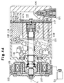
- Fig. 14 shows a prior art variable displacement compressor.
- the compressor includes a housing 101.
- a crank chamber 102 is defined in the housing 101.
- a drive shaft 103 is rotatably supported in the housing 101.
- a lip seal 104 is located between the housing 101 and the drive shaft 103 to prevent gas leakage along the surface of the drive shaft 103.
- the drive shaft 103 is connected to a vehicle engine Eg, which serves as an external power source, through an electromagnetic friction clutch 105.
- the friction clutch 105 includes a pulley 106, an armature 107 and an electromagnetic coil 108.
- the clutch 105 engages, that is, when the coil 108 is excited, the armature 107 is attracted to and is pressed against the pulley 106.
- the clutch 105 transmits the driving force of the engine Eg to the drive shaft 103.
- a rotor 109 is secured to the drive shaft 103 in the crank chamber 102.
- a thrust bearing 122 is located between the rotor 109 and the inner wall of the housing 101.
- a swash plate 110 is coupled to the rotor 109 by a hinge mechanism 111.
- the hinge mechanism 111 permits the swash plate 110 to rotate integrally with the drive shaft 103 and to incline with respect to the axis L of the drive shaft 103.
- Cylinder bores 113, suction chamber 114 and a discharge chamber 115 are defined in the housing 101.
- a piston 116 is reciprocally housed in each cylinder bore 113.
- the pistons 116 are coupled to the swash plate 110.
- the housing 101 includes a valve plate 117.
- the valve plate 117 separates the cylinder bores 113 from the suction chamber 114 and the discharge chamber 115.
- Rotation of the drive shaft 103 is converted into reciprocation of each piston 116 by the rotor 109, the hinge mechanism 111 and the swash plate 110.
- Reciprocation of each piston 116 draws refrigerant gas from the suction chamber 114 to the corresponding cylinder bore 113 via a suction port 117a and a suction valve flap 117b, which are formed in the valve plate 117.
- Refrigerant gas in the cylinder bore 113 is compressed to reach a predetermined pressure and is discharged to the discharge chamber 115 via a discharge port 117c and a discharge valve flap 117d, which are formed in the valve plate 117.
- a spring 118 urges the drive shaft 103 forward (to the left as viewed in Fig. 14) along the axis L through a thrust bearing 123.
- the spring 118 prevents axial chattering of the drive shaft 103.
- the crank chamber 102 is connected to the suction chamber 114 by a bleeding passage 119.
- the discharge chamber 115 is connected to the crank chamber 102 by a supply passage 120.
- the opening of the supply passage 120 is regulated by an electromagnetic displacement control valve 121.
- the control valve 121 adjusts the opening of the supply passage 120 thereby regulating the amount of pressurized refrigerant gas drawn into the crank chamber 102 from the discharge chamber 115.
- the pressure in the crank chamber 102 is changed, accordingly.
- the inclination of the swash plate 110 is altered and the stroke of each piston 116 is changed, which varies the compressor displacement.
- the control valve 121 When the clutch 105 disengages or when the engine Eg is stops, the control valve 121 fully opens the supply passage 120. This increases the pressure in the crank chamber 102 and decreases the inclination of the swash plate 110. The compressor stops operating with the swash plate 110 at the minimum inclination position. When the compressor is started again, the displacement of the compressor is minimum, which requires minimum torque. The shock caused by starting the compressor is thus reduced.
- control valve 121 closes the supply passage 120 and maximizes the compressor displacement.
- the compressor When the clutch 105 disengages or when the engine Eg is stopped, the compressor is stopped. If the compressor is stopped when operating at the maximum displacement, the control valve 121 quickly and fully opens the closed supply passage 120. Also, when the vehicle is suddenly accelerated while the compressor is operating at the maximum displacement, the control valve 121 quickly and fully opens the supply passage 120 to minimize the displacement to reduce the load applied to the engine.
- the sudden increase of the crank chamber pressure suddenly moves the swash plate 110 from the maximum inclination position to the minimum inclination position, which causes the swash plate 110 violently collides with the limit ring 112.
- the collision produces unpleasant noise.
- the swash plate 110 also strongly pulls the drive shaft 103 rearward (to the right as viewed in Fig. 14) through the ring 112 or through the hinge mechanism 111 and the rotor 109. As a result, the drive shaft 103 moves rearward along the axis L against the force of the spring 118.
- the armature 107 which is fixed to the drive shaft 103, moves toward the pulley 106.
- the clearance between the pulley 106 and the armature 107 is as small as 0.5mm when the clutch 105 disengages.
- Rearward movement of the drive shaft 103 eliminates the clearance between the pulley 106 and the armature 107, which may cause the armature 107 to contact the rotating pulley 106.
- noise and vibration are produced.
- the driving force of the engine Eg is transmitted to the drive shaft 103.
- the force of the spring 118 may be set greater. However, a greater force of the spring 118 increases load acting on the thrust bearings 122, 123 and increases power loss of the compressor.
- the control valve 121 suddenly closes the fully opened supply passage 120 to maximize the compressor displacement. Accordingly, the swash plate 110 moves from the minimum inclination position to the maximum inclination position and violently collides with the rotor 109. The collision produces unpleasant noise.
- Japanese Unexamined Patent Publication No. 8-338364 also discloses a variable displacement compressor that has similar drawbacks as the compressor of Fig. 14.
- Another objective of the present invention is to provide displacement control device and method for variable displacement compressors that prevent a swash plate from violently colliding with other parts in the compressor.
- a compressor having a damping device includes a housing, a cylinder bore formed in the housing, a control pressure chamber defined in the housing and a piston housed in the cylinder bore.
- the piston compresses gas drawn into the cylinder bore and discharges the gas from the cylinder bore.
- the compressor further includes a drive shaft, a drive plate and a control valve.
- the drive shaft is rotatably supported by the housing.
- the drive plate is operably coupled to the piston to convert rotation of the drive shaft into reciprocation of the piston.
- the drive plate is supported by the drive shaft to incline relative to the drive shaft and is moved between a maximum inclination position and a minimum inclination position in accordance with the pressure in the control pressure chamber.
- the inclination of the drive plate defines the stroke of the piston and the displacement of the compressor.
- the control valve controls the pressure in the control pressure chamber to change the inclination of the drive plate.
- the control valve is actuated based on an electrical signal.
- the damping device decreases the speed of operation of the control valve.
- the present invention may also be embodied as a method for controlling the displacement of a variable displacement compressor.
- the method includes: controlling the pressure in the control pressure chamber by a control valve to change the inclination of the drive plate, wherein the control valve includes a valve body and an electromagnetic actuator for moving the valve body; controlling current supplied to the electromagnetic actuator, wherein movement of the valve body is controlled in accordance with current supplied to the electromagnetic actuator; and preventing the valve body from being suddenly moved, wherein, when the value of current supplied to the electromagnetic actuator is changed from a first value to a second value, sudden movement of the valve body is prevented by gradually changing the value of the current in at least a part of the range between a first value and a second value.
- variable displacement compressor according to a first embodiment of the present invention will now be described with reference to Figs. 1 to 5.
- the compressor is used in a vehicle air conditioner.
- a front housing 11 is secured to the front end face of a center housing, which is a cylinder block 12 in this embodiment.
- a rear housing 13 is secured to the rear end face of the cylinder block 12, and a valve plate assembly 14 is located between the rear housing 13 and the rear end face.
- the front housing 11, the cylinder block 12, the rear housing 13 form the compressor housing.
- the left in Fig. 1 is defined as the front side of the compressor and the right in Fig. 1 is defined as the rear side of the compressor.
- the valve plate assembly 14 includes a main plate 14a, a first sub-plate 14b, a second sub-plate 14c, and a retainer plate 14d.
- the main plate 14a is located between the first sub-plate 14b and the second sub-plate 14c.
- the retainer plate 14d is located between the second sub-plate 14c and the rear housing member 13.
- a control pressure chamber which is a crank chamber 15 in this embodiment, is defined between the front housing 11 and the cylinder block 12.
- the drive shaft 16 extends through the crank chamber 15 and is rotatably supported by the front housing 11 and the cylinder block 12.
- the drive shaft 16 is supported by the front housing 11 via a radial bearing 17.
- a central bore 12a is formed substantially in the center of the cylinder block 12.
- the rear end of the drive shaft 16 is located in the central bore 12a and is supported by the cylinder block 12 via a radial bearing 18.
- a spring seat 21 is fitted to the wall of the central bore 12a.
- a thrust bearing 19 and a support coil spring 20 are located in the central bore 12a to be between the rear end of the drive shaft 16 and the spring seat 21.
- the support spring 20, or urging means urges the drive shaft 16 forward along the axis L of the drive shaft 16 through the thrust bearing 19.
- the thrust bearing 19 prevents rotation of the drive shaft 16 from being transmitted to the support spring 20.
- a shaft sealing assembly which is a lip seal 22 in this embodiment, is located between the drive shaft 16 and the front housing 11 to prevent leakage of refrigerant gas along the surface of the drive shaft 16.
- the lip seal 22 includes a lip ring 22a, which is pressed against the surface of the drive shaft 16.
- An electromagnetic friction clutch 23 is located between an external power source, which is an engine Eg in this embodiment, and the drive shaft 16.
- the clutch 23 selectively transmits power from the engine Eg to the drive shaft 16.
- the clutch 23 includes a pulley 24, a hub 27, an armature 28, and an electromagnetic coil 29.
- the pulley 24 is rotatably supported by the front end of the front housing 11 via an angular bearing 25.
- a belt 26 is engaged with the pulley 24 to transmit power from the engine Eg to the pulley 24.
- the hub 27, which has elasticity, is fixed to the front end of the drive shaft 16 and supports the armature 28.
- the armature 28 is arranged to face the pulley 24.
- the electromagnetic coil 29 is supported by the front wall of the front housing 11 to face the armature 28.
- a rotor 30 is fixed to the drive shaft 16 in the crank chamber 15.
- a thrust bearing 67 is located between the rotor 30 and the inner wall of the front housing 11.
- a drive plate which is a swash plate 31 in this embodiment, is supported on the drive shaft 16 to slide axially and to incline with respect to the axis L of the drive shaft 16.
- a hinge mechanism 32 is located between the rotor 30 and the swash plate 31.
- the swash plate 31 is coupled to the rotor 30 via the hinge mechanism 32.
- the hinge mechanism 32 rotates the swash plate 31 integrally with the rotor 30.
- the hinge mechanism 32 also guides the swash plate 31 to slide along and incline with respect to the drive shaft 16.
- a coil spring 68 is fitted about the drive shaft 16 and is located between the rotor 30 and the swash plate 31.
- the coil spring 68 urges the swash plate 31 in a direction decreasing the inclination of the swash plate 31.
- a limit ring 34 is attached to the drive shaft 16 between the swash plate 31 and the cylinder block 12. As shown by the broken line in Fig. 1, the inclination of the swash plate 31 is minimized when the swash plate 31 abuts against the limit ring 34. On the other hand, as shown by solid lines in Fig. 1, the inclination of the swash plate 31 is maximized when the swash plate 31 abuts against the rotor 30.
- Cylinder bores 33 (only one is shown in Fig. 1) are formed in the cylinder block 12.
- the cylinder bores 33 are arranged at equal angular intervals about the axis L of the drive shaft 16.
- a single headed piston 35 is accommodated in each cylinder bore 33.
- Each piston 35 is coupled to the swash plate 31 via a pair of shoes 36.
- the swash plate 31 converts rotation of the drive shaft 16 into reciprocation of the pistons 35.
- a suction pressure zone which is a suction chamber 37 in this embodiment, is defined in the substantial center of the rear housing 13.
- a discharge pressure zone which is a discharge chamber 38 in this embodiment, is formed in the rear housing 13 and surrounds the suction chamber 37.
- the main plate 14a of the valve plate assembly 14 includes suction ports 39 and discharge ports 40, which correspond to each cylinder bore 33.
- the first sub-plate 14b includes the suction valves 41, each of which corresponds to one of the suction ports 39.
- the second sub-plate 14c includes the discharge valves 42, each of which corresponds to one of the discharge ports 40.
- the retainer plate 14d includes retainers 43, which correspond to the discharge valves 42. Each retainer 43 determines the maximum opening size of the corresponding discharge valve flap 42.
- a supply passage 44 connects the discharge chamber 38 to the crank chamber 15.
- a bleeding passage 45 connects the crank chamber 15 to the suction chamber 37.
- a displacement control valve 46 is located in the supply passage 44. The control valve 46 adjusts the flow rate of refrigerant gas from the discharge chamber 38 to the crank chamber 15 by varying the opening size of the supply passage 44.
- the pressure in the crank chamber 15 is varied in accordance with the relation between the flow rate of refrigerant gas from the discharge chamber 38 to the crank chamber 15 and that from the crank chamber 15 to the suction chamber 37 through the bleeding passage 45. Accordingly, the difference between the pressure in the crank chamber 15 and the pressure in the cylinder bores 33 is varied, which changes the inclination of the swash plate 31. This alters the stroke of each piston 35 and the displacement.
- valve chamber 51 is defined in the substantial center of the control valve 46.
- a valve body 52 is accommodated in the valve chamber 51.
- An opening of a valve hole 53 in the valve chamber 51 faces the valve body 52.
- the valve chamber 51 and the valve hole 53 form part of the supply passage 44.
- a spring 54 is located in the valve chamber 51 between the wall and the valve body 52 to urge the valve body 52 in a direction opening the valve hole 53.
- a pressure sensing chamber 55 is located above the valve chamber 51.
- the pressure sensing chamber 55 is connected to the suction chamber 37 by a pressure introduction passage 47.
- a pressure sensing member which is a bellows 56 in this embodiment, is accommodated in the pressure sensing chamber 55.
- a spring 57 is located in the bellows 56. The spring 57 determines the initial length of the bellows 56.
- a rod 58 extends from the valve body 52 toward the bellows 56 to operably couple the bellows 56 with the valve body 52.
- a plunger chamber 59 is located below the valve chamber 51.
- a fixed iron core 60 is located between the plunger chamber 59 and the valve chamber 51.
- a plunger which is a movable iron core 61 in this embodiment, is accommodated in the plunger chamber 59.
- a follower spring 62 is accommodated in the plunger chamber 59 to urge the movable iron core 61 toward the valve body 52.
- a guide hole 65 extends through the fixed iron core 60 to communicate the valve chamber 51 with the plunger chamber 59.
- a solenoid rod 63 extends from the valve body 52 through the guide hole 65. The force of the springs 54, 62 causes the distal end of the solenoid rod 63 to contact the movable iron core 61. Accordingly, the valve body 52 and the movable iron core 61 are operably coupled to each other by the solenoid rod 63.
- a coil 64 is located about the fixed iron core 60 and the movable iron core 61.
- the fixed iron core 60, the movable iron core 61, the coil 64 and the solenoid rod 63 form an electromagnetic actuator for moving the valve body 52.
- the suction chamber 37 is connected to the discharge chamber 38 through an external refrigerant circuit 71.
- the external refrigerant circuit 71 includes a condenser 72, an expansion valve 73 and an evaporator 74.
- the external refrigerant circuit 71 and the compressor form a cooling circuit for a vehicle air conditioner.
- An air conditioner switch 80, a passenger compartment temperature sensor 81, a temperature adjuster 82 and an acceleration pedal sensor 83 are connected to a controller C.
- the pedal sensor 83 detects the degree of depression, or position, of a gas pedal.
- Power supply wire is connected to the coil 29 of the clutch 23 and the coil 64 of the control valve 46 from a power source S such as a vehicle battery through the controller C.
- the controller C includes a computer.
- the controller C computes a current value supplied to the coils 29, 64 from the power source S based on various conditions including, for example, an ON/OFF signal from the air conditioner switch 80, the passenger compartment temperature detected by the temperature sensor 81, a target temperature set by the temperature adjuster 82 and a pedal depression amount detected by the acceleration pedal sensor 83.
- the controller C supplies current from the power source S to the coil 29 if the air conditioner switch 80 is turned on and the temperature detected by the compartment temperature sensor 81 is greater than a temperature set by the temperature adjuster 82. Accordingly, the clutch 23 is engaged, which starts the compressor.
- the controller C determines the value of current supplied to the coil 64 of the control valve 46 based on signals from the compartment temperature sensor 81 and the temperature adjuster 82.
- the controller C supplies a current having the determined value from the power source S to the coil 64. Accordingly, an electromagnetic attraction force is generated between the fixed iron core 60 and the movable iron core 61.
- the magnitude of the attraction force corresponds to the value of the received current.
- the attraction force urges the valve body 52 in a direction decreasing the opening size of the valve hole 53.
- the bellows 56 of the control valve 46 expands and contracts in accordance with the pressure (suction pressure) introduced to the pressure sensing chamber 55 from the suction chamber 37.
- the bellows 56 applies a force to the valve body 52 and the magnitude of the force corresponds to the suction pressure in the pressure sensing chamber 55.
- the opening amount of the valve hole 53 is determined based on the force applied to the valve body 52 by the bellows 56, the attraction force between the fixed iron core 60 and the movable iron core 61 and the force of the springs 54, 62.
- the controller C increases the value of the current supplied to the coil 64 when there is a greater difference between the detected compartment temperature and the target temperature, or when the cooling circuit is required to operate with a greater refrigerant performance.
- a greater value of the current increases the magnitude of the attractive force between the fixed core 60 and the movable core 61 thereby increasing the resultant force urging the valve body 52 in a direction closing the valve hole 53. This lowers a target value of the suction pressure.
- the bellows 56 controls the opening of the valve hole 53 with the valve body 52 such that the suction pressure is maintained at the lowered target value. That is, the control valve 46 adjusts the displacement of the compressor such that the lower suction pressure is maintained when the value of current supplied to the coil 64 is greater.
- valve body 52 decreases the opening amount of the valve hole 53. This decreases the amount of refrigerant gas supplied to the crank chamber 15 from the discharge chamber 38. Since refrigerant gas in the crank chamber 15 is constantly conducted to the suction chamber 37, the crank chamber pressure is gradually lowered. This increases the inclination of the swash plate 31, thereby causing the compressor to operate at a larger displacement. A larger compressor displacement increases the cooling performance of the cooling circuit and lowers the suction pressure.
- the controller C decreases the value of the current supplied to the coil 64 when there is a smaller difference between the detected compartment temperature and the target temperature, or when the cooling circuit is required to operate with a smaller refrigerant performance.
- a smaller value of the current decreases the magnitude of the attractive force between the fixed core 60 and the movable core 61 thereby decreasing the resultant force urging the valve body 52 in a direction closing the valve hole 53.
- the bellows 56 controls the opening of the valve hole 53 with the valve body 52 such that the suction pressure is maintained at the raised target value. That is, the control valve 46 adjusts the displacement of the compressor such that a higher suction pressure is maintained when the value of current supplied to the coil 64 is smaller.
- the valve body 52 increases the opening amount of the valve hole 53. This increases the amount of refrigerant gas supplied to the crank chamber 15 from the discharge chamber 38. If the amount of refrigerant gas supplied from the discharge chamber 38 to the crank chamber 15 is greater than the amount of refrigerant gas released from the crank chamber 15 to the suction chamber 37, the crank chamber pressure 15 gradually increases. This decreases the inclination of the swash plate 31, thereby causing the compressor to operate at a smaller displacement. A smaller compressor displacement decreases the cooling performance of the cooling circuit and raises the suction pressure.
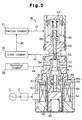
- the control valve 46 includes a damping device. That is, as shown in Figs. 2 and 3, a damper chamber 90 is formed in the fixed core 60 and is located in the guide hole 65. A fluid, preferably oil O, fills the damper chamber 90. A flange 91 is formed on the solenoid rod 63 at part located in the damper chamber 90. The flange 91 functions as a resistor or as a pressure receiver. The flange 91 divides the damper chamber 90 into a first fluid chamber 90a and a second fluid chamber 90b. The outer diameter of the flange 91 is slightly smaller than the inner diameter of the damper chamber 90. Therefore, a passage 92 is defined between the flange 91 and the wall of the damper chamber 90. The passage 92 communicates the fluid chambers 90a, 90b with each other.
- the solenoid rod 63 moves in a direction from the state of Fig. 2 to the state of Fig. 3 or in the reverse direction relative to the fixed core 60, the flange 91 changes the volume ratio between the fluid chambers 90a, 90b.
- the oil O flows through the passage 92 between the fluid chambers 90a, 90b.
- the flow resistance of the oil O generated in the passage 92 acts on the solenoid rod 63. That is, the damping device, which includes the damper chamber 90, the flange 91 and the passage 92, applies resistance to the solenoid rod 63 to prevent the valve body 52 from being quickly moved.
- the controller C stops supplying current to the coil 64 of the control valve 46 for a predetermined period. Accordingly, there is no attractive force between the fixed core 60 and the movable core 61, which fully opens the supply passage 44. Thus, the inclination of the swash plate 31 is minimized and the compressor displacement is also minimized. As a result, the load on the engine Eg is reduced, which permits the vehicle to be quickly accelerated.
- the controller C stops supplying current to the coil 29 thereby disengaging the clutch 23, which stops the compressor. At the same time, the controller C stops supplying current to the coil 64 of the control valve 46. If the engine Eg is stopped while the compressor is operating, the power supply wire from the power source S to the coils 29, 64 is disconnected at a part upstream of the controller C. Accordingly, the clutch 23 is disengaged and the compressor is stopped.
- the solenoid rod 63 is moved from the position of Fig. 3 to the position of Fig. 2. Accordingly, the flange 91 changes the volume ratio between the fluid chambers 90a, 90b. As a result, the oil O flows between the fluid chambers 90a, 90b through the passage 92. The flow resistance of the oil O generated in the passage 92 acts on the solenoid rod 63 through the flange 91. This prevents the valve body 52, which is fixed to the solenoid rod 63, from being suddenly moved. Thus, the valve body 52 slowly opens the valve hole 53.
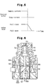
- Fig. 5 is a graph showing changes of the opening amount of the valve hole 53 when current supply to the control valve 46 is stopped. As shown in the graph, the current to the control valve 46 is stopped instantaneously. When the current supply to the control valve 46 is stopped, the valve hole 53, which is fully closed, is gradually opened to the fully opened state. This gradual change of the opening amount is caused by the damping device.
- the swash plate 31 is not quickly moved from the maximum inclination position to the minimum inclination position. This prevents the swash plate 31 from colliding with the limit ring 34 thereby suppressing noise generated by collision.
- the swash plate 31 does not strongly pulls the drive shaft 16 rearward. The drive shaft 16 is therefore not moved rearward against the force of the support spring 20.
- the control valve 46 controls the amount of highly pressurized gas supplied to the crank chamber 15. Compared to a control valve that controls the amount of gas released from the crank chamber 15, the control valve 46 quickly changes the crank chamber pressure. Accordingly, the inclination of the swash plate 31, or the compressor displacement, is quickly changed. However, from a different point of view, the control valve 46 tends to excessively increase the crank chamber pressure 15 compared to a control valve that controls the amount of gas released from the crank chamber 15. It is therefore very effective to form a damping device in the control valve 46, which controls the amount of highly pressurized refrigerant gas supplied to the crank chamber 15.
- the structure of the control valve 46 may be changed such that attractive force generated between the fixed core 60 and the movable core 61 moves the valve body 52 in a direction increasing the opening amount of the valve hole 53.
- Such change to the control valve 46 does not deviate from the concept of the present invention.
- the power supply wire between the coil 64 and the power source S must be also modified. Specifically, the power supply wire must not be disconnected at a part upstream of the controller C. If the wire is disconnected at a part upstream of the controller, the compressor displacement is not minimized when the engine Eg is stopped.
- the modification to the power supply wire requires a major change to the electric system of a conventional vehicle.
- the attractive force between the fixed core 60 and the movable core 61 urges the valve body 52 in a direction decreasing the opening amount of the valve hole 53.
- disconnecting the power supply wire between the coil 64 and the power source S at a part upstream of the controller C causes the valve hole 53 to open thereby minimizing the compressor displacement.
- the compressor displacement is minimized when the engine Eg is stopped without changing the conventional electric system of a vehicle.
- the controller C When the air conditioner switch 80 is turned on, the controller C starts supplying current to the coil 29 thereby engaging the clutch 23, which starts the compressor. If there is a relatively great cooling demand on a refrigeration circuit at this time, the controller C starts sending current having a relatively great magnitude to the coil 64 of the control valve 46 at the same time as the air conditioner switch 80 is turned on. Accordingly, the compressor displacement is maximized.
- the control valve 46 closes the fully opened supply passage 44. That is, the solenoid rod 63 is moved from the position of Fig. 2 to the position of Fig. 3. At this time, the damping device applies resistance to the solenoid rod 63, which prevents the valve body 52 from being quickly moved. The valve body 52 therefore slowly closes the valve hole 53.
- the swash plate 31 is not suddenly moved from the minimum inclination position to the maximum inclination position. As a result, the swash plate 31 does not violently collide with the rotor 30 and noise due to the collision is not produced.
- the plunger chamber 59 also functions as a damper chamber 90.
- the plunger chamber 59 is filled with oil O.
- the movable iron core 61 is located in the plunger chamber 59 and functions as a resistance body or a pressure receiver.
- the movable core 61 has the same functions as the flange 91 in the control valve 46 of Fig. 2.
- the movable core 61 divides the plunger chamber 59 into a first fluid chamber 90a and a second fluid chamber 90b.
- the movable core 61 has a passage 92 to communicate the fluid chambers 90a, 90b with each other.
- the oil O flows between the fluid chambers 90a, 90b.
- the flow resistance of the oil O acts on the valve body 52. That is, the oil O applies resistance to the valve body 52 through the movable core 61 and the solenoid rod 63.
- the valve body 52 is therefore prevented from suddenly moved, which permits the valve body 52 to slowly open or close the valve hole 53.
- the control valve 46 of Fig. 6 functions in the same manner as that of Figs. 1 to 5 and has the same advantages. Particularly, in the control valve 46 of Fig. 6, the plunger chamber 59 is used as the damper chamber 90 and the movable core 61 is used as the resistance body (pressure receiver) In other words, the control valve 46 of the second embodiment does not require an exclusive damping device and therefore has a simplified structure.
- FIG. 7 A third embodiment of the present invention will now be described with reference to Figs. 7 to 9.
- the differences from the embodiment of Figs. 1-5 will mainly be discussed below, and like or the same reference numerals are given to those components that are like or the same as the corresponding components of the embodiment of Figs 1 to 5.
- a control valve 46 is substantially the same as the control valve 46 of Fig. 2 except that the control valve 46 does not have the damping device.
- the compressor of Fig. 7 does not have an electromagnetic friction clutch.
- the compressor of Fig. 7 has a mechanism for stopping flow of refrigerant gas into the compressor.
- a shutter 75 is accommodated in the central bore 12a.
- the shutter 75 slides axially.
- a spring 76 extends between the shutter 75 and the inner wall of the central bore 12a.
- the spring 76 urges the shutter 75 toward the swash plate 31.
- the rear end of the drive shaft 16 is supported by the inner wall of the central bore 12a through a radial bearing 77 and the shutter 75.
- the radial bearing 77 permits the shutter 75 and the drive shaft 16 to rotate relative to each other.
- a suction passage 84 is formed in the center of the rear housing 13.
- the suction passage 84 connects the external refrigerant circuit 71 to the central bore 12a.
- the suction passage 84 is disconnected from the central bore 12a. The shutter 75 cannot be moved further rearward.
- a thrust bearing 78 is located between the swash plate 31 and the shutter 75.
- the swash plate 31 and the shutter 75 are pressed against each other by the springs 68, 75, which permits the swash plate 31 and the shutter 75 move integrally in the axial direction of the drive shaft 16.
- the thrust bearing 78 prevents rotation of the swash plate 31 from being transmitted to the shutter 75.
- the swash plate 31 moves rearward as its inclination decreases.
- the rearward movement of the swash plate 31 is transmitted to the shutter 75 by the thrust bearing 78.
- the swash plate 31 pushes the shutter 75 rearward against the force of the spring 76.
- the shutter 75 contacts the valve plate assembly 14, the swash plate 31 reaches the minimum inclination.
- An axial passage 85 is formed in the drive shaft 16 to connect the crank chamber 15 to the interior of the central bore 12a.
- a pressure release hole 75a is formed in the shutter wall near the rear end of the shutter 75 for connecting the interior of the shutter 75 with the central bore 12a.
- the suction chamber 37 is connected with the central bore 12a by a communication hole 79 formed in the valve plate assembly 14.
- the axial passage 85, the pressure release hole 75a and the communication hole 79 function as a bleeding passage, which corresponds to the bleeding passage 45 of Fig. 1, for communicating the crank chamber 15 with the suction chamber 37.
- the shutter 75 disconnects the hole 79 from the suction passage 84, which stops flow of refrigerant gas from the external refrigerant circuit 71 to the suction chamber 37. In other words, when the swash plate 31 is at the minimum inclination position and the compressor is operating with the minimum displacement, flow of refrigerant from the circuit 71 to the compressor is stopped.
- the minimum inclination of the swash plate 31 is slightly more than zero degrees. Therefore, even if the inclination of the swash plate 31, refrigerant gas is discharged from the cylinder bores 33 to the discharge chamber 38. Refrigerant gas discharged to the discharge chamber 38 flows to the crank chamber 15 through the supply passage 44. Refrigerant gas in the crank chamber 15 flows to the suction chamber 37 through the bleeding passage, which includes the axial passage 85, the pressure release hole 75a and the hole 79. Refrigerant gas in the suction chamber 37 is drawn into the cylinder bores 33 again.
- refrigerant gas circulates within the compressor traveling through the discharge chamber 38, the supply passage 44, the crank chamber 15, the bleeding passage, the suction chamber 37 and the cylinder bores 33.
- the circulation of refrigerant gas causes lubricant oil contained in the gas to lubricate the moving parts of the compressor.
- the shutter 75 When the inclination of the swash plate 31 is greater than the minimum inclination, the shutter 75 is separated from the valve plate assembly 14, which permits refrigerant gas to flow from the external refrigerant circuit 71 to the suction chamber 37 through the suction passage 84. Accordingly, refrigerant starts circulating between the circuit 71 and the compressor.
- a method for controlling the control valve 46 will now be described with reference to Figs. 9(A) to 9(D).
- a signal S1 is sent to the controller C as shown in the graph of Fig. 9(A).
- the signal S1 causes the controller C to start supplying current to the control valve 46.
- the controller C compares the temperature detected by the compartment temperature sensor 81 and the target temperature set by the temperature adjuster 82 and determines a target value of the current supplied to the control valve 46 based on the temperature comparison.
- the graph of Fig. 9(C) shows changes of current supplied to the control valve 46.
- a level Ix represents a target current value computed when the signal S1 is received by the controller C.
- the target current value is varied in accordance with the difference between the temperature detected by the compartment temperature sensor 81 and the temperature set by the temperature adjuster 82.
- the controller C gradually increases the current to the control valve 46 from zero to the target current value Ix in response to the input of the signal S1. Accordingly, the valve body 52 of the control valve 46 gradually decreases the opening amount of the valve hole 53, which gradually lowers the pressure in the crank chamber 15.
- a level line P1 shows a suction pressure before the air conditioner switch 80 is turned on.
- a line P2 shows the suction pressure that is being lowered as the inclination of the swash plate 31 increases.
- a level line P3 in the graph of Fig. 9(B) shows a suction pressure corresponding to the target current value Ix.
- a signal S2 is sent to the controller C as shown in the graph of Fig. 9(A).
- the signal S2 causes the controller C to stop supplying current to the control valve 46. Accordingly, the controller C gradually decreases the supply current value from the target current value Iy at the time of input of the signal S2 to zero as shown in a line E2 of the graph of Fig. 9(C). Accordingly, the valve body 52 of the control valve 46 gradually increases the opening amount of the valve hole 53, which gradually increases the pressure in the crank chamber 15.
- a level line P4 shows a suction pressure before the air conditioner switch 80 is turned off.
- a line P5 shows the suction pressure that is being increased as the inclination of the swash plate 31 decreases.
- a level line P6 in the graph of Fig. 9(B) shows the suction pressure after the refrigerant circulation is stopped.
- the graphs of Figs. 9(A) to 9(D) describe a case where the current to the control valve 46 is started and stopped in response to the signals S1, S2, which are produced based on manipulation of the air conditioner switch 80.
- the current to the control valve 46 is also started and stopped based on conditions other than the signals S1, S2.
- the current supply is controlled in the same manner as shown in Figs. 9(A) to 9(D). Also, not only when the current to the control valve 46 is started or stopped, but also when the target value of the current supplied to the control valve 46 is changed, the method of Figs. 9(A) to 9(D) may be performed.
- Figs. 7 to 9 has substantially the same advantages as the embodiment of Figs. 1 to 5. That is, when current supply to the control valve 46 is started, the supply current is gradually increased from zero to the target current value. Thus, the valve body 52 is gradually moved, which gradually increases the inclination of the swash plate 31. As a result, the swash plate 31 is not moved beyond an inclination position that corresponds to the target current value. Also, the swash plate 31 is prevented from violently collide with the rotor 30.
- the control valve 46 of the third embodiment does not require a mechanical damping device. Instead, the method for controlling the control valve 46 is changed. Thus, the third embodiment is relatively easy to implement at a relatively low cost.
- the speed of the valve body 52 corresponds to the ratio of change of the current to the control valve 46. Therefore, unlike a mechanical damping device, the speed of the valve body 52 is therefore arbitrarily changed by the controller C.
- the ratio of change of the current to the control valve 46 may be optimized for the conditions (for example, the value of the target current) when starting or stopping supplying current to the control valve 46.
- the value of supply current may be instantaneously increased from zero to a target current value or may be instantaneously decreased from a target current value to zero. This is effective when the compressor displacement needs to be instantaneously increased or decreased.
- the vehicle electric system may be changed such that current can be supplied to the control valve 46 even if the engine Eg is not running. In this case, the supply current value to the control valve 46 may be gradually decreased even if the engine Eg is stopped.
- the supply current value does not need to be changed in a continuous manner.
- the supply current value may be changed discretely as shown by two-dot chain lines E1' and E2' in the graph of Fig. 9(C).
- FIG. 10 A fourth embodiment of the present invention will now be described with reference to Figs. 10 and 11. The differences from the embodiment of Figs. 7 to 9 will mainly be discussed below.
- the suction pressure in the suction chamber 37 is detected by a suction pressure sensor 86.
- the crank chamber pressure is detected by a crank chamber pressure sensor 87.
- the sensors 86, 87 send detection data to the controller C.
- the controller C stores first and second control maps (both are not shown).
- the suction pressure and the supply current value are used as variables in the first control map.
- the crank chamber pressure and the supply current value are used as variables in the second control map.
- the controller C controls the current based on the pressure data obtained by the suction pressure sensor 86 referring to the first control map.
- the controller C controls the current to the control valve 46 based on the pressure data obtained by the crank chamber pressure sensor 87 referring to the second control map.
- a method for controlling the control valve 46 will now be described with reference to Fig. 11.
- a signal S1 is sent to the controller C as shown in the graph of Fig. 11(A).
- the signal S1 causes the controller C to start supplying current to the control valve 46.
- the controller C compares the temperature detected by the compartment temperature sensor 81 and the target temperature set by the temperature adjuster 82 and determines a target value of the current supplied to the control valve 46 based on the temperature comparison.
- the determined target current value is defined as a value Ix as shown in the graph of Fig. 11(C).
- the controller C also computes an instant increase current value Iz based on the target current value Ix and the suction pressure detected by the suction pressure sensor 86 referring to the first control map.
- the instant increase current value Iz is smaller than the target current value Ix.
- the instant increase current value Iz is an upper limit value to which the current supplied to the control valve 46 can be instantaneously increased when the controller C starts supplying current to the control valve 46.
- the controller C instantaneously increases the supply current from zero the value Iz as illustrated by a line D1 in the graph of Fig. 11(C). Then, as illustrated by a line D2 of the graph of Fig. 11(C), the controller C gradually increases the current to the control valve 46 from the value Iz to the target current value Ix. Accordingly, the valve body 52 of the control valve 46 instantaneously decreases the opening amount of the valve hole 53 to an opening amount that corresponds to the value Iz. The valve body 52 then gradually decreases the opening amount of the valve hole 53 to an opening amount that corresponds to the value Ix. As the supply current value gradually increases from the value Iz to the value Ix, the pressure in the crank chamber 15 gradually decreases, accordingly.
- a level line Q1 shows a suction pressure before the air conditioner switch 80 is turned on.
- a line Q2 shows the suction pressure that is being lowered as the inclination of the swash plate 31 increases.
- the swash plate 31 When the supply current value reaches the target current value Ix, the swash plate 31 is moved to an inclination position that corresponds to the target current value Ix, and the suction pressure seeks a value that corresponds to the target value Ix.
- a line Q3 in the graph of Fig. 11(B) shows a suction pressure that corresponds to the target current value Ix.
- a signal S2 is sent to the controller C as shown in the graph of Fig. 11(A).
- the signal S2 causes the controller C to stop supplying current to the control valve 46.
- the controller C also computes an instant decrease current value Iw based on the target current value Iy at the time of input of the signal S2 and the crank chamber pressure detected by the crank chamber pressure sensor 87 referring to the second control map.
- the instant decrease current value Iw is a lower limit value to which the current supplied to the control valve 46 can be instantaneously decreased when the controller C receives the signal S2.
- the controller C instantaneously decreases the supply current from the target value Iy at the time of input of the signal S2 to the instant decrease value Iw. Then, as illustrated by a line D4 of the graph of Fig. 11(C), the controller C gradually decreases the current value from the value Iw to zero.
- the valve body 52 of the control valve 46 instantaneously increases the opening amount of the valve hole 53 to an opening amount that corresponds to the value Iw.
- the valve body 52 then gradually increases the opening amount of the valve hole 53.
- the crank chamber pressure gradually increases, accordingly.
- a line Q4 shows the suction pressure before the air conditioner switch 80 is turned off
- a line Q5 shows the suction pressure as the swash plate inclination slowly decreases.
- the graphs of Figs. 11(A) to 11(D) describe a case where the current to the control valve 46 is started and stopped in response to the signals S1, S2, which are produced based on manipulation of the air conditioner switch 80.
- the current to the control valve 46 is also started and stopped based on conditions other than the signals S1, S2.
- the current supply is controlled in the same manner as shown in Figs. 11(A) to 11(D). Also, not only when the current to the control valve 46 is started or stopped, but also when the target value of the current supplied to the control valve 46 is changed, the method of Figs. 11(A) to 11(D) may be performed.
- the instant increase current value Iz is computed based on the current target current value Ix and the suction pressure. Then, after the supply current is instantaneously increased to the value Iz from zero, the current is gradually increased to the target current value Ix.
- the instant increase value Iz is an upper limit value to which the current can be instantaneously increased without causing the swash plate 31 to collide with the rotor 30.
- the value Iz varies depending on the suction pressure. That is, if the supply current is instantaneously increased to a value that is higher than the value Iz, the swash plate 31 can collide with the rotor 30 and produce noise. Increasing the supply current to the instant increase value Iz quickly increases the swash plate inclination without producing noise and quickly increases the compressor displacement.
- the instant decrease current value Iw is computed based on the current target current value Iy and the crank chamber pressure. Then, the supply current is instantaneously decreased from the target current value Iy to the value Iw. Thereafter, the supply current is gradually decreased to zero.
- the instant decrease value Iw is a minimum value to which the supply current can be instantaneously decreased without causing the shutter 75, which moves integrally with the swash plate 31, to collide with the valve plate assembly 14.
- the value Iw is changed depending on the crank chamber pressure. That is, if the supply current is instantaneously decreased to a value that is lower than the value Iw, the shutter 75 can collide with the valve plate assembly 14 and produce noise. Decreasing the supply current to the instant decrease value Iw quickly decreases the swash plate inclination without producing noise and quickly decreases the compressor displacement.
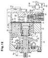
- FIG. 12 A fifth embodiment of the present invention will now be described with reference to Figs. 12 and 13. The differences from the embodiment of Figs. 7 to 9 will mainly be discussed below.
- a compressor of the fifth embodiment has a control valve 88 that is different from the control valve 46 of Fig. 7. Specifically, the control valve 88 does not have a pressure sensing mechanism, which moves a valve body in accordance with the suction pressure. The control valve 88 operates in accordance with electric current from the outside.
- the compressor of the fifth embodiment is the same as the compressor of Fig. 7 except for the control valve 88.
- the electromagnetic control valve 88 includes a valve hole 95, a valve body 96 that faces the valve hole 95 and an electromagnetic actuator for moving the valve body 96.
- the actuator is a solenoid 97 in this embodiment.
- the solenoid 97 When the solenoid 97 is excited, the valve body 96 closes the valve hole 95, which moves the swash plate 31 to the maximum inclination position.
- the solenoid 97 When the solenoid 97 is de-excited, the valve body 96 maximizes the opening amount of the valve hole 95, which moves the swash plate 31 to the minimum inclination position.
- the controller C de-excites the solenoid 97.
- the controller C excites the solenoid 97 if the temperature detected by the compartment temperature sensor 81 is greater than a target temperature set by the temperature adjuster 82.
- the controller C de-excites the solenoid 97.
- the solenoid 97 is excited, the controller C de-excites the solenoid 97 for a predetermined period if the vehicle is rapidly accelerated, that is, if the acceleration pedal depression amount detected by the acceleration pedal sensor 83 is greater than a predetermined value.
- a method for controlling the control valve 88 will now be described with reference to Fig. 13.
- the controller C When exciting the solenoid 97, the controller C gradually increases the current supplied to the solenoid 97 as shown by a line F1 in the graph of Fig. 13(C). The maximum value of the current corresponds to the target current value.
- a signal S3 in the graph of Fig. 13(A) represents a command to start supplying current to the solenoid 97.
- a line G1 in the graph of Fig. 13(D) shows an increase of the swash plate inclination in accordance with the increase of the supply current.
- a line R1 in the graph of Fig. 13(B) shows an increase of the suction pressure in accordance with the increase of the swash plate inclination.
- the controller C When de-exciting the solenoid 97, the controller C gradually decreases the current supplied to the solenoid 97 as shown by a line F2 in the graph of Fig. 13(C).
- a signal S4 in the graph of Fig. 13(A) represents a command to stop supplying current to the solenoid 97.
- a line G2 in the graph of Fig. 13(D) shows a decrease of the swash plate inclination in accordance with the decrease of the supply current.
- a line R2 in the graph of Fig. 13(B) shows a decrease of the suction pressure in accordance with the decrease of the swash plate inclination.
- the supply current value may be changed discretely as shown by two-dot chain lines E1' and E2' in the graph of Fig. 9(C).
- the control valve 88 may be controlled by the method of the embodiment of Figs. 10 and 11.
- the current to the control valve may be gradually changed only when the swash plate 31 is moved from the minimum inclination position to the maximum inclination position.
- the current to the control valve may be gradually changed only when the swash plate 31 is moved from the maximum inclination position to the minimum inclination position. In this manner, the compressor displacement can be quickly changed when the parts of the compressor do not collide with each other or when the drive shaft 16 does not move axially.
- current value supplied to the control valve 46 may be gradually increased to a value that is greater than a target value and then be gradually decreased to the target value. This prevents the swash plate 31 from moving too fast only in the vicinity of the target inclination position and the compressor displacement is quickly increased.
- current to the control valve 46 may be controlled by a duty cycle.
- the average of the current value per unit time is defined as the supply current value.
- the pressure sensing mechanism which includes the bellows 56, may be omitted from the control valve 46.
- the control valve 88 of Fig. 12 may include the damping device of the control valve 46 of Fig. 2.
- the clutch 23 may be omitted from the compressor of Fig. 1.
- the compressor of Fig. 1 may include the shutter 75 of Fig. 7.
- the clutch 23 of Fig. 1 may be used in the compressors of Figs. 7, 10 and 12.
- the shutter 75 may be omitted from the compressor of Figs. 7, 10 and 12.
- a control valve may be located in the bleeding passage, which connects the crank chamber 15 to the suction chamber 37.
- the present invention may be embodied in any type of compressor as long as it includes a displacement control valve.
- the present invention may be embodied in wobble plate type compressors.
- a wobble plate type compressor includes pistons. Each piston includes a rod that is connected to a wobble plate. As a drive shaft rotates, the wobble plate wobbles without being rotated.
- a variable displacement compressor includes a swash plate (31) and a displacement control valve (46; 88).
- the swash plate is moved between a maximum inclination position and a minimum inclination position in accordance with the pressure in a crank chamber (15).
- the control valve changes the crank chamber pressure to change the swash plate inclination.
- the control valve includes a valve body (52; 96) and an electromagnetic actuator (60, 61, 64; 97) for moving the valve body. Movement of the valve body is controlled according to current supplied to the actuator.
- the control valve also includes a fluid damper (90, 91; 59, 61) for applying fluid resistance to the valve body. The fluid resistance prevents the valve body from moving too quickly. The fluid damper therefore prevents the crank chamber pressure from being suddenly changed. Also, the fluid damper prevents the swash plate inclination from being suddenly changed. Instead of using the fluid damper, the sudden movement of the valve body may be prevented by controlling current supplied to the electromagnetic actuator.
Landscapes
- Engineering & Computer Science (AREA)
- Mechanical Engineering (AREA)
- General Engineering & Computer Science (AREA)
- Compressors, Vaccum Pumps And Other Relevant Systems (AREA)
Abstract
Description
- The present invention relates to a variable displacement compressor used in vehicle air conditioners. Specifically, the present invention pertains to a device and a method for controlling the displacement of a variable displacement compressor.
- Fig. 14 shows a prior art variable displacement compressor. The compressor includes a
housing 101. Acrank chamber 102 is defined in thehousing 101. Adrive shaft 103 is rotatably supported in thehousing 101. Alip seal 104 is located between thehousing 101 and thedrive shaft 103 to prevent gas leakage along the surface of thedrive shaft 103. - The
drive shaft 103 is connected to a vehicle engine Eg, which serves as an external power source, through anelectromagnetic friction clutch 105. Thefriction clutch 105 includes apulley 106, anarmature 107 and anelectromagnetic coil 108. When theclutch 105 engages, that is, when thecoil 108 is excited, thearmature 107 is attracted to and is pressed against thepulley 106. As a result, theclutch 105 transmits the driving force of the engine Eg to thedrive shaft 103. - When the
clutch 105 disengages, that is, when thecoil 108 is de-excited, thearmature 107 is separated from thepulley 106. In this state, the driving force of the engine Eg is not transmitted to thedrive shaft 103. - A
rotor 109 is secured to thedrive shaft 103 in thecrank chamber 102. A thrust bearing 122 is located between therotor 109 and the inner wall of thehousing 101. Aswash plate 110 is coupled to therotor 109 by ahinge mechanism 111. Thehinge mechanism 111 permits theswash plate 110 to rotate integrally with thedrive shaft 103 and to incline with respect to the axis L of thedrive shaft 103. When theswash plate 110 abuts against alimit ring 112 fitted about thedrive shaft 103 as illustrated by two-dot chain line in Fig. 14, theswash plate 110 is at the minimum inclination position. When theswash plate 110 abuts against therotor 109 as illustrated by solid line in Fig. 14, theswash plate 110 is at the maximum inclination position. -
Cylinder bores 113,suction chamber 114 and adischarge chamber 115 are defined in thehousing 101. Apiston 116 is reciprocally housed in eachcylinder bore 113. Thepistons 116 are coupled to theswash plate 110. Thehousing 101 includes avalve plate 117. Thevalve plate 117 separates thecylinder bores 113 from thesuction chamber 114 and thedischarge chamber 115. - Rotation of the
drive shaft 103 is converted into reciprocation of eachpiston 116 by therotor 109, thehinge mechanism 111 and theswash plate 110. Reciprocation of eachpiston 116 draws refrigerant gas from thesuction chamber 114 to thecorresponding cylinder bore 113 via asuction port 117a and asuction valve flap 117b, which are formed in thevalve plate 117. Refrigerant gas in thecylinder bore 113 is compressed to reach a predetermined pressure and is discharged to thedischarge chamber 115 via adischarge port 117c and adischarge valve flap 117d, which are formed in thevalve plate 117. - A
spring 118 urges thedrive shaft 103 forward (to the left as viewed in Fig. 14) along the axis L through a thrust bearing 123. Thespring 118 prevents axial chattering of thedrive shaft 103. - The
crank chamber 102 is connected to thesuction chamber 114 by ableeding passage 119. Thedischarge chamber 115 is connected to thecrank chamber 102 by asupply passage 120. The opening of thesupply passage 120 is regulated by an electromagneticdisplacement control valve 121. - The
control valve 121 adjusts the opening of thesupply passage 120 thereby regulating the amount of pressurized refrigerant gas drawn into thecrank chamber 102 from thedischarge chamber 115. The pressure in thecrank chamber 102 is changed, accordingly. As a result, the inclination of theswash plate 110 is altered and the stroke of eachpiston 116 is changed, which varies the compressor displacement. - When the
clutch 105 disengages or when the engine Eg is stops, thecontrol valve 121 fully opens thesupply passage 120. This increases the pressure in thecrank chamber 102 and decreases the inclination of theswash plate 110. The compressor stops operating with theswash plate 110 at the minimum inclination position. When the compressor is started again, the displacement of the compressor is minimum, which requires minimum torque. The shock caused by starting the compressor is thus reduced. - When there is a relatively great cooling demand on a refrigeration circuit that includes the compressor of Fig. 14, for example, when the temperature in a passenger compartment of a vehicle is much higher than a target temperature set in advance, the
control valve 121 closes thesupply passage 120 and maximizes the compressor displacement. - When the
clutch 105 disengages or when the engine Eg is stopped, the compressor is stopped. If the compressor is stopped when operating at the maximum displacement, thecontrol valve 121 quickly and fully opens the closedsupply passage 120. Also, when the vehicle is suddenly accelerated while the compressor is operating at the maximum displacement, thecontrol valve 121 quickly and fully opens thesupply passage 120 to minimize the displacement to reduce the load applied to the engine. - Accordingly, highly pressurized refrigerant gas in the
discharge chamber 115 is quickly supplied to thecrank chamber 102, which rapidly increases the pressure in thecrank chamber 102. Refrigerant gas in thecrank chamber 102 constantly flows to thesuction chamber 114 through thebleeding passage 119. However, since the amount of refrigerant gas that flows to thesuction chamber 114 through thebleeding passage 119 is limited, the pressure in thecrank chamber 102 is quickly increased an excessive level. - The sudden increase of the crank chamber pressure suddenly moves the
swash plate 110 from the maximum inclination position to the minimum inclination position, which causes theswash plate 110 violently collides with thelimit ring 112. The collision produces unpleasant noise. Theswash plate 110 also strongly pulls thedrive shaft 103 rearward (to the right as viewed in Fig. 14) through thering 112 or through thehinge mechanism 111 and therotor 109. As a result, thedrive shaft 103 moves rearward along the axis L against the force of thespring 118. - When the
drive shaft 103 moves rearward, the axial position of thedrive shaft 103 relative to thelip seal 104, which is retained in thehousing 101, changes. Normally, a predetermined annular area of thedrive shaft 103 contacts thelip seal 104. Foreign particles and sludge adhere to a surface of thedrive shaft 103 that is axially adjacent to the predetermined annular area. Therefore, if the axial position of thedrive shaft 103 relative to thelip seal 104 changes, sludge enters between thelip seal 104 and thedrive shaft 103. This lowers the effectiveness of thelip seal 104 and results in gas leakage from thecrank chamber 102. - Particularly, when the
drive shaft 103 moves rearward due to disengagement of theclutch 105, thearmature 107, which is fixed to thedrive shaft 103, moves toward thepulley 106. The clearance between thepulley 106 and thearmature 107 is as small as 0.5mm when theclutch 105 disengages. Rearward movement of thedrive shaft 103 eliminates the clearance between thepulley 106 and thearmature 107, which may cause thearmature 107 to contact the rotatingpulley 106. As a result, noise and vibration are produced. Also, even if theclutch 105 disengages, the driving force of the engine Eg is transmitted to thedrive shaft 103. - When the
drive shaft 103 moves rearward, the average position of thepistons 116, which are coupled to thedrive shaft 103 by theswash plate 110, is moved rearward. This causes the top dead center of eachpiston 116 to approach thevalve plate 117. If the compressor is operating, thepistons 116 may repeatedly collide with thevalve plate 117, which produces vibration and noise. - To prevent the
drive shaft 103 from moving rearward, the force of thespring 118 may be set greater. However, a greater force of thespring 118 increases load acting on thethrust bearings - If the compressor starts operating by engagement of the clutch 105 when there is a relatively great cooling demand on a refrigeration circuit that includes the compressor of Fig. 14, the
control valve 121 suddenly closes the fully openedsupply passage 120 to maximize the compressor displacement. Accordingly, theswash plate 110 moves from the minimum inclination position to the maximum inclination position and violently collides with therotor 109. The collision produces unpleasant noise. - Japanese Unexamined Patent Publication No. 8-338364 also discloses a variable displacement compressor that has similar drawbacks as the compressor of Fig. 14.
- Accordingly, it is an objective of the present invention to provide displacement control device and method for variable displacement compressors that prevent crank chamber pressure from being excessively increased.
- Another objective of the present invention is to provide displacement control device and method for variable displacement compressors that prevent a swash plate from violently colliding with other parts in the compressor.
- To achieve the foregoing and other objectives and in accordance with the purpose of the present invention, a compressor having a damping device is provided. The compressor includes a housing, a cylinder bore formed in the housing, a control pressure chamber defined in the housing and a piston housed in the cylinder bore. The piston compresses gas drawn into the cylinder bore and discharges the gas from the cylinder bore. The compressor further includes a drive shaft, a drive plate and a control valve. The drive shaft is rotatably supported by the housing. The drive plate is operably coupled to the piston to convert rotation of the drive shaft into reciprocation of the piston. The drive plate is supported by the drive shaft to incline relative to the drive shaft and is moved between a maximum inclination position and a minimum inclination position in accordance with the pressure in the control pressure chamber. The inclination of the drive plate defines the stroke of the piston and the displacement of the compressor. The control valve controls the pressure in the control pressure chamber to change the inclination of the drive plate. The control valve is actuated based on an electrical signal. The damping device decreases the speed of operation of the control valve.
- The present invention may also be embodied as a method for controlling the displacement of a variable displacement compressor. The method includes: controlling the pressure in the control pressure chamber by a control valve to change the inclination of the drive plate, wherein the control valve includes a valve body and an electromagnetic actuator for moving the valve body; controlling current supplied to the electromagnetic actuator, wherein movement of the valve body is controlled in accordance with current supplied to the electromagnetic actuator; and preventing the valve body from being suddenly moved, wherein, when the value of current supplied to the electromagnetic actuator is changed from a first value to a second value, sudden movement of the valve body is prevented by gradually changing the value of the current in at least a part of the range between a first value and a second value.
- Other aspects and advantages of the invention will become apparent from the following description, taken in conjunction with the accompanying drawings, illustrating by way of example the principles of the invention.
- The invention, together with objects and advantages thereof, may best be understood by reference to the following description of the presently preferred embodiments together with the accompanying drawings.
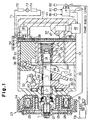
- Fig. 1 is a cross-sectional view illustrating a variable displacement compressor according to a first embodiment of the present invention;
- Fig. 2 is an enlarged cross-sectional view illustrating the displacement control valve used in the compressor of Fig. 1;
- Fig. 3 is an enlarged partial cross-sectional view illustrating the displacement control valve of Fig. 2 when a valve hole is closed;
- Fig. 4 is an enlarged partial cross-sectional view illustrating the clutch of Fig. 1 when it is disengaged;
- Fig. 5 is a chart showing the operational characteristics of the compressor shown in Fig. 2;
- Fig. 6 is an enlarged partial cross-sectional view illustrating a displacement control valve according to a second embodiment of the present invention;
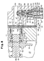
- Fig. 7 is a cross-sectional view illustrating a compressor according to a third embodiment of the present invention;
- Fig. 8 is an enlarged partial cross-sectional view illustrating the compressor of Fig. 7 when the inclination of the swash plate is maximum;
- Figs. 9(A) to 9(D) are graphs showing the value of current supplied to the control valve, the swash plate inclination and the suction pressure of the compressor shown in Fig. 7;
- Fig. 10 is a cross-sectional view illustrating a compressor according to a fourth embodiment of the present invention;
- Figs. 11(A) to 11(D) are graphs showing the value of current supplied to the control valve, the swash plate inclination and the suction pressure of the compressor shown in Fig. 10;
- Fig. 12 is a cross-sectional view illustrating a compressor according to a fifth embodiment of the present invention;
- Figs. 13(A) to 13(D) are graphs showing the value of current supplied to the control valve, the swash plate inclination and the suction pressure of the compressor shown in Fig. 12; and
- Fig. 14 is a cross-sectional view illustrating a prior art compressor.
-
- A variable displacement compressor according to a first embodiment of the present invention will now be described with reference to Figs. 1 to 5. The compressor is used in a vehicle air conditioner.
- As shown in Fig. 1, a
front housing 11 is secured to the front end face of a center housing, which is acylinder block 12 in this embodiment. Arear housing 13 is secured to the rear end face of thecylinder block 12, and avalve plate assembly 14 is located between therear housing 13 and the rear end face. Thefront housing 11, thecylinder block 12, therear housing 13 form the compressor housing. The left in Fig. 1 is defined as the front side of the compressor and the right in Fig. 1 is defined as the rear side of the compressor. - The
valve plate assembly 14 includes amain plate 14a, a first sub-plate 14b, a second sub-plate 14c, and aretainer plate 14d. Themain plate 14a is located between the first sub-plate 14b and the second sub-plate 14c. Theretainer plate 14d is located between the second sub-plate 14c and therear housing member 13. - A control pressure chamber, which is a
crank chamber 15 in this embodiment, is defined between thefront housing 11 and thecylinder block 12. Thedrive shaft 16 extends through thecrank chamber 15 and is rotatably supported by thefront housing 11 and thecylinder block 12. - The
drive shaft 16 is supported by thefront housing 11 via aradial bearing 17. Acentral bore 12a is formed substantially in the center of thecylinder block 12. The rear end of thedrive shaft 16 is located in thecentral bore 12a and is supported by thecylinder block 12 via aradial bearing 18. Aspring seat 21 is fitted to the wall of thecentral bore 12a. Athrust bearing 19 and asupport coil spring 20 are located in thecentral bore 12a to be between the rear end of thedrive shaft 16 and thespring seat 21. Thesupport spring 20, or urging means, urges thedrive shaft 16 forward along the axis L of thedrive shaft 16 through thethrust bearing 19. Thethrust bearing 19 prevents rotation of thedrive shaft 16 from being transmitted to thesupport spring 20. - The front end of the
drive shaft 16 projects from the front end of thefront housing 11. A shaft sealing assembly, which is alip seal 22 in this embodiment, is located between thedrive shaft 16 and thefront housing 11 to prevent leakage of refrigerant gas along the surface of thedrive shaft 16. Thelip seal 22 includes a lip ring 22a, which is pressed against the surface of thedrive shaft 16. - An electromagnetic friction clutch 23 is located between an external power source, which is an engine Eg in this embodiment, and the
drive shaft 16. The clutch 23 selectively transmits power from the engine Eg to thedrive shaft 16. The clutch 23 includes apulley 24, ahub 27, anarmature 28, and anelectromagnetic coil 29. Thepulley 24 is rotatably supported by the front end of thefront housing 11 via anangular bearing 25. Abelt 26 is engaged with thepulley 24 to transmit power from the engine Eg to thepulley 24. Thehub 27, which has elasticity, is fixed to the front end of thedrive shaft 16 and supports thearmature 28. Thearmature 28 is arranged to face thepulley 24. Theelectromagnetic coil 29 is supported by the front wall of thefront housing 11 to face thearmature 28. - When the
coil 29 is excited while the engine Eg is running, an attraction force based on electromagnetic force is generated between thearmature 28 and thepulley 24. Accordingly, thearmature 28 contacts thepulley 24 against the force of thehub 27, which engages the clutch 23. When the clutch 23 is engaged, power from the engine Eg is transmitted to thedrive shaft 16 via thebelt 26 and the clutch 23 (See Fig. 1). When thecoil 29 is de-excited in this state, thearmature 28 is separated from thepulley 24 by the force of thehub 27 as shown in Fig. 4, which disengages the clutch 23. When the clutch 23 is disengaged, transmission of power from the engine Eg to thedrive shaft 16 is disconnected. - As shown in Fig. 1, a
rotor 30 is fixed to thedrive shaft 16 in thecrank chamber 15. Athrust bearing 67 is located between therotor 30 and the inner wall of thefront housing 11. A drive plate, which is aswash plate 31 in this embodiment, is supported on thedrive shaft 16 to slide axially and to incline with respect to the axis L of thedrive shaft 16. Ahinge mechanism 32 is located between therotor 30 and theswash plate 31. Theswash plate 31 is coupled to therotor 30 via thehinge mechanism 32. Thehinge mechanism 32 rotates theswash plate 31 integrally with therotor 30. Thehinge mechanism 32 also guides theswash plate 31 to slide along and incline with respect to thedrive shaft 16. - A
coil spring 68 is fitted about thedrive shaft 16 and is located between therotor 30 and theswash plate 31. Thecoil spring 68 urges theswash plate 31 in a direction decreasing the inclination of theswash plate 31. - A limit ring 34 is attached to the
drive shaft 16 between theswash plate 31 and thecylinder block 12. As shown by the broken line in Fig. 1, the inclination of theswash plate 31 is minimized when theswash plate 31 abuts against the limit ring 34. On the other hand, as shown by solid lines in Fig. 1, the inclination of theswash plate 31 is maximized when theswash plate 31 abuts against therotor 30. - Cylinder bores 33 (only one is shown in Fig. 1) are formed in the
cylinder block 12. The cylinder bores 33 are arranged at equal angular intervals about the axis L of thedrive shaft 16. A single headedpiston 35 is accommodated in each cylinder bore 33. Eachpiston 35 is coupled to theswash plate 31 via a pair ofshoes 36. Theswash plate 31 converts rotation of thedrive shaft 16 into reciprocation of thepistons 35. - A suction pressure zone, which is a
suction chamber 37 in this embodiment, is defined in the substantial center of therear housing 13. A discharge pressure zone, which is adischarge chamber 38 in this embodiment, is formed in therear housing 13 and surrounds thesuction chamber 37. Themain plate 14a of thevalve plate assembly 14 includessuction ports 39 anddischarge ports 40, which correspond to each cylinder bore 33. The first sub-plate 14b includes thesuction valves 41, each of which corresponds to one of thesuction ports 39. The second sub-plate 14c includes thedischarge valves 42, each of which corresponds to one of thedischarge ports 40. Theretainer plate 14d includesretainers 43, which correspond to thedischarge valves 42. Eachretainer 43 determines the maximum opening size of the correspondingdischarge valve flap 42. - When each
piston 35 moves from the top dead center position to the bottom dead center position, refrigerant gas in thesuction chamber 37 flows into the corresponding cylinder bore 33 via the correspondingsuction port 39 andsuction valve flap 41. When eachpiston 35 moves from the bottom dead center position to the top dead center position, refrigerant gas in the corresponding cylinder bore 33 is compressed to a predetermined pressure and is discharged to thedischarge chamber 38 via thecorresponding discharge port 40 anddischarge valve flap 42. - A
supply passage 44 connects thedischarge chamber 38 to the crankchamber 15. A bleedingpassage 45 connects thecrank chamber 15 to thesuction chamber 37. Adisplacement control valve 46 is located in thesupply passage 44. Thecontrol valve 46 adjusts the flow rate of refrigerant gas from thedischarge chamber 38 to the crankchamber 15 by varying the opening size of thesupply passage 44. The pressure in thecrank chamber 15 is varied in accordance with the relation between the flow rate of refrigerant gas from thedischarge chamber 38 to the crankchamber 15 and that from thecrank chamber 15 to thesuction chamber 37 through the bleedingpassage 45. Accordingly, the difference between the pressure in thecrank chamber 15 and the pressure in the cylinder bores 33 is varied, which changes the inclination of theswash plate 31. This alters the stroke of eachpiston 35 and the displacement. - A
control valve 46 will now be described. As shown in Fig. 2, avalve chamber 51 is defined in the substantial center of thecontrol valve 46. Avalve body 52 is accommodated in thevalve chamber 51. An opening of avalve hole 53 in thevalve chamber 51 faces thevalve body 52. Thevalve chamber 51 and thevalve hole 53 form part of thesupply passage 44. Aspring 54 is located in thevalve chamber 51 between the wall and thevalve body 52 to urge thevalve body 52 in a direction opening thevalve hole 53. - A pressure sensing chamber 55 is located above the
valve chamber 51. The pressure sensing chamber 55 is connected to thesuction chamber 37 by apressure introduction passage 47. A pressure sensing member, which is a bellows 56 in this embodiment, is accommodated in the pressure sensing chamber 55. Aspring 57 is located in thebellows 56. Thespring 57 determines the initial length of thebellows 56. Arod 58 extends from thevalve body 52 toward thebellows 56 to operably couple thebellows 56 with thevalve body 52. - A
plunger chamber 59 is located below thevalve chamber 51. A fixediron core 60 is located between theplunger chamber 59 and thevalve chamber 51. A plunger, which is amovable iron core 61 in this embodiment, is accommodated in theplunger chamber 59. Afollower spring 62 is accommodated in theplunger chamber 59 to urge themovable iron core 61 toward thevalve body 52. Aguide hole 65 extends through the fixediron core 60 to communicate thevalve chamber 51 with theplunger chamber 59. Asolenoid rod 63 extends from thevalve body 52 through theguide hole 65. The force of thesprings solenoid rod 63 to contact themovable iron core 61. Accordingly, thevalve body 52 and themovable iron core 61 are operably coupled to each other by thesolenoid rod 63. - A
coil 64 is located about the fixediron core 60 and themovable iron core 61. The fixediron core 60, themovable iron core 61, thecoil 64 and thesolenoid rod 63 form an electromagnetic actuator for moving thevalve body 52. - As shown in Fig. 1, the
suction chamber 37 is connected to thedischarge chamber 38 through an externalrefrigerant circuit 71. The externalrefrigerant circuit 71 includes acondenser 72, anexpansion valve 73 and anevaporator 74. The externalrefrigerant circuit 71 and the compressor form a cooling circuit for a vehicle air conditioner. - An
air conditioner switch 80, a passengercompartment temperature sensor 81, atemperature adjuster 82 and anacceleration pedal sensor 83 are connected to a controller C. Thepedal sensor 83 detects the degree of depression, or position, of a gas pedal. Power supply wire is connected to thecoil 29 of the clutch 23 and thecoil 64 of thecontrol valve 46 from a power source S such as a vehicle battery through the controller C. - The controller C includes a computer. The controller C computes a current value supplied to the
coils air conditioner switch 80, the passenger compartment temperature detected by thetemperature sensor 81, a target temperature set by thetemperature adjuster 82 and a pedal depression amount detected by theacceleration pedal sensor 83. - Generally, when the engine Eg is stopped (specifically, when the key switch is turned off), electrical devices of a vehicle are not supplied with electric power. When the engine Eg is stopped, the electric supply wire between the
coils coils - The operation of the compressor will now be described. When the engine Eg is running, the controller C supplies current from the power source S to the
coil 29 if theair conditioner switch 80 is turned on and the temperature detected by thecompartment temperature sensor 81 is greater than a temperature set by thetemperature adjuster 82. Accordingly, the clutch 23 is engaged, which starts the compressor. - The controller C determines the value of current supplied to the
coil 64 of thecontrol valve 46 based on signals from thecompartment temperature sensor 81 and thetemperature adjuster 82. The controller C supplies a current having the determined value from the power source S to thecoil 64. Accordingly, an electromagnetic attraction force is generated between the fixediron core 60 and themovable iron core 61. The magnitude of the attraction force corresponds to the value of the received current. The attraction force urges thevalve body 52 in a direction decreasing the opening size of thevalve hole 53. The bellows 56 of thecontrol valve 46 expands and contracts in accordance with the pressure (suction pressure) introduced to the pressure sensing chamber 55 from thesuction chamber 37. The bellows 56 applies a force to thevalve body 52 and the magnitude of the force corresponds to the suction pressure in the pressure sensing chamber 55. - Thus, the opening amount of the
valve hole 53 is determined based on the force applied to thevalve body 52 by thebellows 56, the attraction force between the fixediron core 60 and themovable iron core 61 and the force of thesprings - The controller C increases the value of the current supplied to the
coil 64 when there is a greater difference between the detected compartment temperature and the target temperature, or when the cooling circuit is required to operate with a greater refrigerant performance. A greater value of the current increases the magnitude of the attractive force between the fixedcore 60 and themovable core 61 thereby increasing the resultant force urging thevalve body 52 in a direction closing thevalve hole 53. This lowers a target value of the suction pressure. The bellows 56 controls the opening of thevalve hole 53 with thevalve body 52 such that the suction pressure is maintained at the lowered target value. That is, thecontrol valve 46 adjusts the displacement of the compressor such that the lower suction pressure is maintained when the value of current supplied to thecoil 64 is greater. - When the current supplied to the
coil 64 is increased, or when the suction pressure increases, thevalve body 52 decreases the opening amount of thevalve hole 53. This decreases the amount of refrigerant gas supplied to the crankchamber 15 from thedischarge chamber 38. Since refrigerant gas in thecrank chamber 15 is constantly conducted to thesuction chamber 37, the crank chamber pressure is gradually lowered. This increases the inclination of theswash plate 31, thereby causing the compressor to operate at a larger displacement. A larger compressor displacement increases the cooling performance of the cooling circuit and lowers the suction pressure. - The controller C decreases the value of the current supplied to the
coil 64 when there is a smaller difference between the detected compartment temperature and the target temperature, or when the cooling circuit is required to operate with a smaller refrigerant performance. A smaller value of the current decreases the magnitude of the attractive force between the fixedcore 60 and themovable core 61 thereby decreasing the resultant force urging thevalve body 52 in a direction closing thevalve hole 53. This raises a target value of the suction pressure. The bellows 56 controls the opening of thevalve hole 53 with thevalve body 52 such that the suction pressure is maintained at the raised target value. That is, thecontrol valve 46 adjusts the displacement of the compressor such that a higher suction pressure is maintained when the value of current supplied to thecoil 64 is smaller. - When the current value to the
coil 64 is decreased, or when the suction pressure is lowered, thevalve body 52 increases the opening amount of thevalve hole 53. This increases the amount of refrigerant gas supplied to the crankchamber 15 from thedischarge chamber 38. If the amount of refrigerant gas supplied from thedischarge chamber 38 to the crankchamber 15 is greater than the amount of refrigerant gas released from thecrank chamber 15 to thesuction chamber 37, thecrank chamber pressure 15 gradually increases. This decreases the inclination of theswash plate 31, thereby causing the compressor to operate at a smaller displacement. A smaller compressor displacement decreases the cooling performance of the cooling circuit and raises the suction pressure. - The characteristic structure of the above compressor will now be described.
- One of the characteristics is that the
control valve 46 includes a damping device. That is, as shown in Figs. 2 and 3, adamper chamber 90 is formed in the fixedcore 60 and is located in theguide hole 65. A fluid, preferably oil O, fills thedamper chamber 90. Aflange 91 is formed on thesolenoid rod 63 at part located in thedamper chamber 90. Theflange 91 functions as a resistor or as a pressure receiver. Theflange 91 divides thedamper chamber 90 into a firstfluid chamber 90a and a secondfluid chamber 90b. The outer diameter of theflange 91 is slightly smaller than the inner diameter of thedamper chamber 90. Therefore, apassage 92 is defined between theflange 91 and the wall of thedamper chamber 90. Thepassage 92 communicates thefluid chambers - The
solenoid rod 63 moves in a direction from the state of Fig. 2 to the state of Fig. 3 or in the reverse direction relative to the fixedcore 60, theflange 91 changes the volume ratio between thefluid chambers passage 92 between thefluid chambers passage 92 acts on thesolenoid rod 63. That is, the damping device, which includes thedamper chamber 90, theflange 91 and thepassage 92, applies resistance to thesolenoid rod 63 to prevent thevalve body 52 from being quickly moved. - The operation of the damping device will now be described.
- When wishing to quickly accelerate the vehicle, a driver depresses the acceleration pedal by a great amount. If the
acceleration pedal sensor 83 detects an acceleration depression degree that is greater than a predetermined value while the compressor is operating, the controller C stops supplying current to thecoil 64 of thecontrol valve 46 for a predetermined period. Accordingly, there is no attractive force between the fixedcore 60 and themovable core 61, which fully opens thesupply passage 44. Thus, the inclination of theswash plate 31 is minimized and the compressor displacement is also minimized. As a result, the load on the engine Eg is reduced, which permits the vehicle to be quickly accelerated. - If the
air conditioner switch 80 is turned off while the compressor is operating, the controller C stops supplying current to thecoil 29 thereby disengaging the clutch 23, which stops the compressor. At the same time, the controller C stops supplying current to thecoil 64 of thecontrol valve 46. If the engine Eg is stopped while the compressor is operating, the power supply wire from the power source S to thecoils - When the clutch 23 is disengaged or when the engine Eg is stopped, current supply to the
coil 64 of thecontrol valve 46 is stopped. At this time, thecontrol valve 46 fully opens thesupply passage 44. Therefore, when the compressor is not operating, the inclination of theswash plate 31 is minimum. When the compressor is started again, the displacement of the compressor is minimum, which requires minimum torque. The shock caused by starting the compressor is thus reduced. - If the
control valve 46 fully opens thesupply passage 44 when the compressor is operating at the maximum displacement, in other words, if thecontrol valve 46 fully opens thesupply passage 44 after thesupply passage 44 is fully closed, thesolenoid rod 63 is moved from the position of Fig. 3 to the position of Fig. 2. Accordingly, theflange 91 changes the volume ratio between thefluid chambers fluid chambers passage 92. The flow resistance of the oil O generated in thepassage 92 acts on thesolenoid rod 63 through theflange 91. This prevents thevalve body 52, which is fixed to thesolenoid rod 63, from being suddenly moved. Thus, thevalve body 52 slowly opens thevalve hole 53. - Fig. 5 is a graph showing changes of the opening amount of the
valve hole 53 when current supply to thecontrol valve 46 is stopped. As shown in the graph, the current to thecontrol valve 46 is stopped instantaneously. When the current supply to thecontrol valve 46 is stopped, thevalve hole 53, which is fully closed, is gradually opened to the fully opened state. This gradual change of the opening amount is caused by the damping device. - Therefore, highly pressurized gas does not suddenly flows to the crank
chamber 15 from thedischarge chamber 38, which prevents the crank chamber pressure from being suddenly increased. Thus, stopping the current to thecontrol valve 46 does not excessively increase thecrank chamber pressure 15. - As a result, the
swash plate 31 is not quickly moved from the maximum inclination position to the minimum inclination position. This prevents theswash plate 31 from colliding with the limit ring 34 thereby suppressing noise generated by collision. When at the minimum inclination position, theswash plate 31 does not strongly pulls thedrive shaft 16 rearward. Thedrive shaft 16 is therefore not moved rearward against the force of thesupport spring 20. - Since the
drive shaft 16 is prevented from axially displaced, the drawbacks described in the prior art section, specifically, displacement of thedrive shaft 16 relative to thelip seal 22, contact between thearmature 28 and thepulley 24 when the clutch 23 is disengaged and collision of thepistons 35 against thevalve plate assembly 14, are all resolved. - The
control valve 46 controls the amount of highly pressurized gas supplied to the crankchamber 15. Compared to a control valve that controls the amount of gas released from thecrank chamber 15, thecontrol valve 46 quickly changes the crank chamber pressure. Accordingly, the inclination of theswash plate 31, or the compressor displacement, is quickly changed. However, from a different point of view, thecontrol valve 46 tends to excessively increase thecrank chamber pressure 15 compared to a control valve that controls the amount of gas released from thecrank chamber 15. It is therefore very effective to form a damping device in thecontrol valve 46, which controls the amount of highly pressurized refrigerant gas supplied to the crankchamber 15. - The structure of the
control valve 46 may be changed such that attractive force generated between the fixedcore 60 and themovable core 61 moves thevalve body 52 in a direction increasing the opening amount of thevalve hole 53. Such change to thecontrol valve 46 does not deviate from the concept of the present invention. If this change is made, the power supply wire between thecoil 64 and the power source S must be also modified. Specifically, the power supply wire must not be disconnected at a part upstream of the controller C. If the wire is disconnected at a part upstream of the controller, the compressor displacement is not minimized when the engine Eg is stopped. The modification to the power supply wire requires a major change to the electric system of a conventional vehicle. - However, in the
control valve 46, the attractive force between the fixedcore 60 and themovable core 61 urges thevalve body 52 in a direction decreasing the opening amount of thevalve hole 53. Thus, when the engine Eg is stopped, disconnecting the power supply wire between thecoil 64 and the power source S at a part upstream of the controller C causes thevalve hole 53 to open thereby minimizing the compressor displacement. In other words, the compressor displacement is minimized when the engine Eg is stopped without changing the conventional electric system of a vehicle. - When the
air conditioner switch 80 is turned on, the controller C starts supplying current to thecoil 29 thereby engaging the clutch 23, which starts the compressor. If there is a relatively great cooling demand on a refrigeration circuit at this time, the controller C starts sending current having a relatively great magnitude to thecoil 64 of thecontrol valve 46 at the same time as theair conditioner switch 80 is turned on. Accordingly, the compressor displacement is maximized. Thecontrol valve 46 closes the fully openedsupply passage 44. That is, thesolenoid rod 63 is moved from the position of Fig. 2 to the position of Fig. 3. At this time, the damping device applies resistance to thesolenoid rod 63, which prevents thevalve body 52 from being quickly moved. Thevalve body 52 therefore slowly closes thevalve hole 53. - Therefore, the
swash plate 31 is not suddenly moved from the minimum inclination position to the maximum inclination position. As a result, theswash plate 31 does not violently collide with therotor 30 and noise due to the collision is not produced. - A second embodiment of the present invention will now be described with reference to Fig. 6. In the second embodiment, the
plunger chamber 59 also functions as adamper chamber 90. Theplunger chamber 59 is filled with oil O. Themovable iron core 61 is located in theplunger chamber 59 and functions as a resistance body or a pressure receiver. In other words, themovable core 61 has the same functions as theflange 91 in thecontrol valve 46 of Fig. 2. Themovable core 61 divides theplunger chamber 59 into a firstfluid chamber 90a and a secondfluid chamber 90b. Themovable core 61 has apassage 92 to communicate thefluid chambers - As the
movable core 61 moves axially, the oil O flows between thefluid chambers valve body 52. That is, the oil O applies resistance to thevalve body 52 through themovable core 61 and thesolenoid rod 63. Thevalve body 52 is therefore prevented from suddenly moved, which permits thevalve body 52 to slowly open or close thevalve hole 53. - The
control valve 46 of Fig. 6 functions in the same manner as that of Figs. 1 to 5 and has the same advantages. Particularly, in thecontrol valve 46 of Fig. 6, theplunger chamber 59 is used as thedamper chamber 90 and themovable core 61 is used as the resistance body (pressure receiver) In other words, thecontrol valve 46 of the second embodiment does not require an exclusive damping device and therefore has a simplified structure. - A third embodiment of the present invention will now be described with reference to Figs. 7 to 9. The differences from the embodiment of Figs. 1-5 will mainly be discussed below, and like or the same reference numerals are given to those components that are like or the same as the corresponding components of the embodiment of Figs 1 to 5.
- In the embodiment of Figs. 7 to 9, sudden movements of the
valve body 52 are prevented by controlling current supplied to thecontrol valve 46. As shown in Figs. 7 and 8, acontrol valve 46 is substantially the same as thecontrol valve 46 of Fig. 2 except that thecontrol valve 46 does not have the damping device. Unlike the compressor of Fig. 1, the compressor of Fig. 7 does not have an electromagnetic friction clutch. Further, the compressor of Fig. 7 has a mechanism for stopping flow of refrigerant gas into the compressor. - The differences between the compressor of Fig. 1 and the compressor of the third embodiment will now be described. As shown in Fig. 7, the distal end of the
drive shaft 16 is directly coupled to the engine Eg without an electromagnetic friction clutch. As shown in Figs. 7 and 8, ashutter 75 is accommodated in thecentral bore 12a. Theshutter 75 slides axially. Aspring 76 extends between theshutter 75 and the inner wall of thecentral bore 12a. Thespring 76 urges theshutter 75 toward theswash plate 31. The rear end of thedrive shaft 16 is supported by the inner wall of thecentral bore 12a through aradial bearing 77 and theshutter 75. Theradial bearing 77 permits theshutter 75 and thedrive shaft 16 to rotate relative to each other. - A
suction passage 84 is formed in the center of therear housing 13. Thesuction passage 84 connects the externalrefrigerant circuit 71 to thecentral bore 12a. When the rear end of theshutter 75 contacts thevalve plate assembly 14 as shown in Fig. 8, thesuction passage 84 is disconnected from thecentral bore 12a. Theshutter 75 cannot be moved further rearward. - A
thrust bearing 78 is located between theswash plate 31 and theshutter 75. Theswash plate 31 and theshutter 75 are pressed against each other by thesprings swash plate 31 and theshutter 75 move integrally in the axial direction of thedrive shaft 16. Thethrust bearing 78 prevents rotation of theswash plate 31 from being transmitted to theshutter 75. - The
swash plate 31 moves rearward as its inclination decreases. The rearward movement of theswash plate 31 is transmitted to theshutter 75 by thethrust bearing 78. As theswash plate 31 moves rearward, theswash plate 31 pushes theshutter 75 rearward against the force of thespring 76. When theshutter 75 contacts thevalve plate assembly 14, theswash plate 31 reaches the minimum inclination. - An
axial passage 85 is formed in thedrive shaft 16 to connect thecrank chamber 15 to the interior of thecentral bore 12a. Apressure release hole 75a is formed in the shutter wall near the rear end of theshutter 75 for connecting the interior of theshutter 75 with thecentral bore 12a. Thesuction chamber 37 is connected with thecentral bore 12a by acommunication hole 79 formed in thevalve plate assembly 14. Theaxial passage 85, thepressure release hole 75a and thecommunication hole 79 function as a bleeding passage, which corresponds to the bleedingpassage 45 of Fig. 1, for communicating thecrank chamber 15 with thesuction chamber 37. - When contacting the
valve plate assembly 14, theshutter 75 disconnects thehole 79 from thesuction passage 84, which stops flow of refrigerant gas from the externalrefrigerant circuit 71 to thesuction chamber 37. In other words, when theswash plate 31 is at the minimum inclination position and the compressor is operating with the minimum displacement, flow of refrigerant from thecircuit 71 to the compressor is stopped. - The minimum inclination of the
swash plate 31 is slightly more than zero degrees. Therefore, even if the inclination of theswash plate 31, refrigerant gas is discharged from the cylinder bores 33 to thedischarge chamber 38. Refrigerant gas discharged to thedischarge chamber 38 flows to the crankchamber 15 through thesupply passage 44. Refrigerant gas in thecrank chamber 15 flows to thesuction chamber 37 through the bleeding passage, which includes theaxial passage 85, thepressure release hole 75a and thehole 79. Refrigerant gas in thesuction chamber 37 is drawn into the cylinder bores 33 again. That is, when the inclination of theswash plate 31 is minimum, refrigerant gas circulates within the compressor traveling through thedischarge chamber 38, thesupply passage 44, thecrank chamber 15, the bleeding passage, thesuction chamber 37 and the cylinder bores 33. The circulation of refrigerant gas causes lubricant oil contained in the gas to lubricate the moving parts of the compressor. - When the inclination of the
swash plate 31 is greater than the minimum inclination, theshutter 75 is separated from thevalve plate assembly 14, which permits refrigerant gas to flow from the externalrefrigerant circuit 71 to thesuction chamber 37 through thesuction passage 84. Accordingly, refrigerant starts circulating between thecircuit 71 and the compressor. - A method for controlling the
control valve 46 will now be described with reference to Figs. 9(A) to 9(D). When theair conditioner switch 80 is turned on, a signal S1 is sent to the controller C as shown in the graph of Fig. 9(A). The signal S1 causes the controller C to start supplying current to thecontrol valve 46. Accordingly, the controller C compares the temperature detected by thecompartment temperature sensor 81 and the target temperature set by thetemperature adjuster 82 and determines a target value of the current supplied to thecontrol valve 46 based on the temperature comparison. - The graph of Fig. 9(C) shows changes of current supplied to the
control valve 46. A level Ix represents a target current value computed when the signal S1 is received by the controller C. The target current value is varied in accordance with the difference between the temperature detected by thecompartment temperature sensor 81 and the temperature set by thetemperature adjuster 82. - As illustrated by a line E1 of the graph of Fig. 9(C), the controller C gradually increases the current to the
control valve 46 from zero to the target current value Ix in response to the input of the signal S1. Accordingly, thevalve body 52 of thecontrol valve 46 gradually decreases the opening amount of thevalve hole 53, which gradually lowers the pressure in thecrank chamber 15. - As the pressure in the
crank chamber 15 is slowly lowered, the inclination of theswash plate 31 gradually increases from the minimum inclination as shown in a line K1 of the graph of Fig. 9(D). That is, the compressor displacement gradually increases from the minimum displacement. This starts circulation of refrigerant between the externalrefrigerant circuit 71 and the compressor and gradually lowers the suction pressure. In the graph of Fig. 9(B), a level line P1 shows a suction pressure before theair conditioner switch 80 is turned on. A line P2 shows the suction pressure that is being lowered as the inclination of theswash plate 31 increases. - When the supply current level reaches the target level Ix, the
swash plate 31 is moved to a inclination position corresponding to the value Ix and the suction pressure seeks a value corresponding to the target current level Ix. A level line P3 in the graph of Fig. 9(B) shows a suction pressure corresponding to the target current value Ix. - When the
air conditioner switch 80 is turned off, a signal S2 is sent to the controller C as shown in the graph of Fig. 9(A). The signal S2 causes the controller C to stop supplying current to thecontrol valve 46. Accordingly, the controller C gradually decreases the supply current value from the target current value Iy at the time of input of the signal S2 to zero as shown in a line E2 of the graph of Fig. 9(C). Accordingly, thevalve body 52 of thecontrol valve 46 gradually increases the opening amount of thevalve hole 53, which gradually increases the pressure in thecrank chamber 15. - As the pressure in the
crank chamber 15 is slowly raised, the inclination of theswash plate 31 gradually decreases from the inclination at the time of input of the signal S2. The swash plate inclination is decreased as shown by a line K2 of the graph of Fig. 9(D), which gradually decreases the compressor displacement. Accordingly, the suction pressure is gradually increased. In the graph of Fig. 9(B), a level line P4 shows a suction pressure before theair conditioner switch 80 is turned off. A line P5 shows the suction pressure that is being increased as the inclination of theswash plate 31 decreases. - When the supply current value is zero, the
swash plate 31 moves to the minimum inclination position, which stops circulation of refrigerant gas between the externalrefrigerant circuit 71 and the compressor. A level line P6 in the graph of Fig. 9(B) shows the suction pressure after the refrigerant circulation is stopped. - The graphs of Figs. 9(A) to 9(D) describe a case where the current to the
control valve 46 is started and stopped in response to the signals S1, S2, which are produced based on manipulation of theair conditioner switch 80. The current to thecontrol valve 46 is also started and stopped based on conditions other than the signals S1, S2. In these cases, the current supply is controlled in the same manner as shown in Figs. 9(A) to 9(D). Also, not only when the current to thecontrol valve 46 is started or stopped, but also when the target value of the current supplied to thecontrol valve 46 is changed, the method of Figs. 9(A) to 9(D) may be performed. - The embodiment of Figs. 7 to 9 has substantially the same advantages as the embodiment of Figs. 1 to 5. That is, when current supply to the
control valve 46 is started, the supply current is gradually increased from zero to the target current value. Thus, thevalve body 52 is gradually moved, which gradually increases the inclination of theswash plate 31. As a result, theswash plate 31 is not moved beyond an inclination position that corresponds to the target current value. Also, theswash plate 31 is prevented from violently collide with therotor 30. - When the current to the
control valve 46 is stopped, the current is gradually decreased from the target current value to zero, which slowly moves thevalve body 52. Accordingly, the inclination of theswash plate 31 is gradually decreased. As a result, theshutter 75, which moves integrally with theswash plate 31, is prevented from violently colliding with thevalve plate assembly 14. - The
control valve 46 of the third embodiment does not require a mechanical damping device. Instead, the method for controlling thecontrol valve 46 is changed. Thus, the third embodiment is relatively easy to implement at a relatively low cost. - The speed of the
valve body 52 corresponds to the ratio of change of the current to thecontrol valve 46. Therefore, unlike a mechanical damping device, the speed of thevalve body 52 is therefore arbitrarily changed by the controller C. Thus, the ratio of change of the current to thecontrol valve 46 may be optimized for the conditions (for example, the value of the target current) when starting or stopping supplying current to thecontrol valve 46. - Also, when necessary, the value of supply current may be instantaneously increased from zero to a target current value or may be instantaneously decreased from a target current value to zero. This is effective when the compressor displacement needs to be instantaneously increased or decreased.
- The vehicle electric system may be changed such that current can be supplied to the
control valve 46 even if the engine Eg is not running. In this case, the supply current value to thecontrol valve 46 may be gradually decreased even if the engine Eg is stopped. - The supply current value does not need to be changed in a continuous manner. For example, the supply current value may be changed discretely as shown by two-dot chain lines E1' and E2' in the graph of Fig. 9(C).
- A fourth embodiment of the present invention will now be described with reference to Figs. 10 and 11. The differences from the embodiment of Figs. 7 to 9 will mainly be discussed below.
- As shown in Fig. 10, the suction pressure in the
suction chamber 37 is detected by asuction pressure sensor 86. The crank chamber pressure is detected by a crankchamber pressure sensor 87. Thesensors - When staring supplying current to the
control valve 46, the controller C controls the current based on the pressure data obtained by thesuction pressure sensor 86 referring to the first control map. When stopping supplying current to thecontrol valve 46, the controller C controls the current to thecontrol valve 46 based on the pressure data obtained by the crankchamber pressure sensor 87 referring to the second control map. - A method for controlling the
control valve 46 will now be described with reference to Fig. 11. When theair conditioner switch 80 is turned on, a signal S1 is sent to the controller C as shown in the graph of Fig. 11(A). The signal S1 causes the controller C to start supplying current to thecontrol valve 46. Accordingly, the controller C compares the temperature detected by thecompartment temperature sensor 81 and the target temperature set by thetemperature adjuster 82 and determines a target value of the current supplied to thecontrol valve 46 based on the temperature comparison. The determined target current value is defined as a value Ix as shown in the graph of Fig. 11(C). - The controller C also computes an instant increase current value Iz based on the target current value Ix and the suction pressure detected by the
suction pressure sensor 86 referring to the first control map. The instant increase current value Iz is smaller than the target current value Ix. The instant increase current value Iz is an upper limit value to which the current supplied to thecontrol valve 46 can be instantaneously increased when the controller C starts supplying current to thecontrol valve 46. - The controller C instantaneously increases the supply current from zero the value Iz as illustrated by a line D1 in the graph of Fig. 11(C). Then, as illustrated by a line D2 of the graph of Fig. 11(C), the controller C gradually increases the current to the
control valve 46 from the value Iz to the target current value Ix. Accordingly, thevalve body 52 of thecontrol valve 46 instantaneously decreases the opening amount of thevalve hole 53 to an opening amount that corresponds to the value Iz. Thevalve body 52 then gradually decreases the opening amount of thevalve hole 53 to an opening amount that corresponds to the value Ix. As the supply current value gradually increases from the value Iz to the value Ix, the pressure in thecrank chamber 15 gradually decreases, accordingly. - As the pressure in the
crank chamber 15 is slowly lowered, the inclination of theswash plate 31 gradually increases from the minimum inclination as shown in a line H1 of the graph of Fig. 11(D). That is, the compressor displacement gradually increases from the minimum displacement. This starts circulation of refrigerant between the externalrefrigerant circuit 71 and the compressor and gradually lowers the suction pressure. In the graph of Fig. 11(B), a level line Q1 shows a suction pressure before theair conditioner switch 80 is turned on. A line Q2 shows the suction pressure that is being lowered as the inclination of theswash plate 31 increases. - When the supply current value reaches the target current value Ix, the
swash plate 31 is moved to an inclination position that corresponds to the target current value Ix, and the suction pressure seeks a value that corresponds to the target value Ix. A line Q3 in the graph of Fig. 11(B) shows a suction pressure that corresponds to the target current value Ix. - When the
air conditioner switch 80 is turned off, a signal S2 is sent to the controller C as shown in the graph of Fig. 11(A). The signal S2 causes the controller C to stop supplying current to thecontrol valve 46. The controller C also computes an instant decrease current value Iw based on the target current value Iy at the time of input of the signal S2 and the crank chamber pressure detected by the crankchamber pressure sensor 87 referring to the second control map. The instant decrease current value Iw is a lower limit value to which the current supplied to thecontrol valve 46 can be instantaneously decreased when the controller C receives the signal S2. - The controller C instantaneously decreases the supply current from the target value Iy at the time of input of the signal S2 to the instant decrease value Iw. Then, as illustrated by a line D4 of the graph of Fig. 11(C), the controller C gradually decreases the current value from the value Iw to zero. First, the
valve body 52 of thecontrol valve 46 instantaneously increases the opening amount of thevalve hole 53 to an opening amount that corresponds to the value Iw. Thevalve body 52 then gradually increases the opening amount of thevalve hole 53. As the supply current value gradually decreases from the value Iw to zero, the crank chamber pressure gradually increases, accordingly. - As the crank chamber pressure slowly increases, the inclination of the
swash plate 31 is gradually decreased from the inclination at the time of input of the signal S2 as shown by a line H2 in the graph of Fig. 11(D). Accordingly, the compressor displacement gradually decreases and the suction pressure gradually increases. In the graph of Fig. 11(B), a line Q4 shows the suction pressure before theair conditioner switch 80 is turned off, a line Q5 shows the suction pressure as the swash plate inclination slowly decreases. - When the supply current is stopped, the
swash plate 31 is moved to the minimum inclination position, which stops circulation of refrigerant between the externalrefrigerant circuit 71 and the compressor. A line Q6 in the graph of Fig. 11(B) shows the suction pressure after the refrigerant circulation is stopped. - The graphs of Figs. 11(A) to 11(D) describe a case where the current to the
control valve 46 is started and stopped in response to the signals S1, S2, which are produced based on manipulation of theair conditioner switch 80. The current to thecontrol valve 46 is also started and stopped based on conditions other than the signals S1, S2. In these cases, the current supply is controlled in the same manner as shown in Figs. 11(A) to 11(D). Also, not only when the current to thecontrol valve 46 is started or stopped, but also when the target value of the current supplied to thecontrol valve 46 is changed, the method of Figs. 11(A) to 11(D) may be performed. - In the fourth embodiment, when current supply to the
control valve 46 is started, the instant increase current value Iz is computed based on the current target current value Ix and the suction pressure. Then, after the supply current is instantaneously increased to the value Iz from zero, the current is gradually increased to the target current value Ix. The instant increase value Iz is an upper limit value to which the current can be instantaneously increased without causing theswash plate 31 to collide with therotor 30. The value Iz varies depending on the suction pressure. That is, if the supply current is instantaneously increased to a value that is higher than the value Iz, theswash plate 31 can collide with therotor 30 and produce noise. Increasing the supply current to the instant increase value Iz quickly increases the swash plate inclination without producing noise and quickly increases the compressor displacement. - When the current to the
control valve 46 is stopped, the instant decrease current value Iw is computed based on the current target current value Iy and the crank chamber pressure. Then, the supply current is instantaneously decreased from the target current value Iy to the value Iw. Thereafter, the supply current is gradually decreased to zero. The instant decrease value Iw is a minimum value to which the supply current can be instantaneously decreased without causing theshutter 75, which moves integrally with theswash plate 31, to collide with thevalve plate assembly 14. The value Iw is changed depending on the crank chamber pressure. That is, if the supply current is instantaneously decreased to a value that is lower than the value Iw, theshutter 75 can collide with thevalve plate assembly 14 and produce noise. Decreasing the supply current to the instant decrease value Iw quickly decreases the swash plate inclination without producing noise and quickly decreases the compressor displacement. - In this manner, the current to the
control valve 46 is gradually changed only immediately before theswash plate 31 reaches a target inclination position. Therefore, the compressor is prevented from producing collision noise and the compressor displacement is quickly changed. - A fifth embodiment of the present invention will now be described with reference to Figs. 12 and 13. The differences from the embodiment of Figs. 7 to 9 will mainly be discussed below.
- As shown in Fig. 12, a compressor of the fifth embodiment has a
control valve 88 that is different from thecontrol valve 46 of Fig. 7. Specifically, thecontrol valve 88 does not have a pressure sensing mechanism, which moves a valve body in accordance with the suction pressure. Thecontrol valve 88 operates in accordance with electric current from the outside. The compressor of the fifth embodiment is the same as the compressor of Fig. 7 except for thecontrol valve 88. - The
electromagnetic control valve 88 includes avalve hole 95, avalve body 96 that faces thevalve hole 95 and an electromagnetic actuator for moving thevalve body 96. The actuator is asolenoid 97 in this embodiment. When thesolenoid 97 is excited, thevalve body 96 closes thevalve hole 95, which moves theswash plate 31 to the maximum inclination position. When thesolenoid 97 is de-excited, thevalve body 96 maximizes the opening amount of thevalve hole 95, which moves theswash plate 31 to the minimum inclination position. - When the
air conditioner switch 80 is turned off, the controller C de-excites thesolenoid 97. When theair conditioner switch 80 is on, the controller C excites thesolenoid 97 if the temperature detected by thecompartment temperature sensor 81 is greater than a target temperature set by thetemperature adjuster 82. When the temperature detected by thesensor 81 is lower than the temperature set by thetemperature adjuster 82, the controller C de-excites thesolenoid 97. When thesolenoid 97 is excited, the controller C de-excites thesolenoid 97 for a predetermined period if the vehicle is rapidly accelerated, that is, if the acceleration pedal depression amount detected by theacceleration pedal sensor 83 is greater than a predetermined value. - A method for controlling the
control valve 88 will now be described with reference to Fig. 13. When exciting thesolenoid 97, the controller C gradually increases the current supplied to thesolenoid 97 as shown by a line F1 in the graph of Fig. 13(C). The maximum value of the current corresponds to the target current value. A signal S3 in the graph of Fig. 13(A) represents a command to start supplying current to thesolenoid 97. A line G1 in the graph of Fig. 13(D) shows an increase of the swash plate inclination in accordance with the increase of the supply current. A line R1 in the graph of Fig. 13(B) shows an increase of the suction pressure in accordance with the increase of the swash plate inclination. - When de-exciting the
solenoid 97, the controller C gradually decreases the current supplied to thesolenoid 97 as shown by a line F2 in the graph of Fig. 13(C). A signal S4 in the graph of Fig. 13(A) represents a command to stop supplying current to thesolenoid 97. A line G2 in the graph of Fig. 13(D) shows a decrease of the swash plate inclination in accordance with the decrease of the supply current. A line R2 in the graph of Fig. 13(B) shows a decrease of the suction pressure in accordance with the decrease of the swash plate inclination. - When the swash plate inclination is increased, the sliding speed of the
swash plate 31 is reduced to prevent theswash plate 31 from colliding with therotor 30. Also, when the swash plate inclination decreases, the sliding speed of theswash plate 31 is reduced to prevent theshutter 75 from colliding with thevalve plate assembly 14. - The supply current value may be changed discretely as shown by two-dot chain lines E1' and E2' in the graph of Fig. 9(C). Alternatively, the
control valve 88 may be controlled by the method of the embodiment of Figs. 10 and 11. - It should be apparent to those skilled in the art that the present invention may be embodied in many other specific forms without departing from the spirit or scope of the invention. More particularly, the present invention may be modified as described below.
- In the embodiments of Figs. 7 to 11, the current to the control valve may be gradually changed only when the
swash plate 31 is moved from the minimum inclination position to the maximum inclination position. Alternatively, the current to the control valve may be gradually changed only when theswash plate 31 is moved from the maximum inclination position to the minimum inclination position. In this manner, the compressor displacement can be quickly changed when the parts of the compressor do not collide with each other or when thedrive shaft 16 does not move axially. - In the embodiment of Figs. 7 to 9, current value supplied to the
control valve 46 may be gradually increased to a value that is greater than a target value and then be gradually decreased to the target value. This prevents theswash plate 31 from moving too fast only in the vicinity of the target inclination position and the compressor displacement is quickly increased. - In the embodiments of Figs. 7 to 13, current to the
control valve 46 may be controlled by a duty cycle. In this case, the average of the current value per unit time is defined as the supply current value. - In the embodiments of Figs. 1 to 11, the pressure sensing mechanism, which includes the
bellows 56, may be omitted from thecontrol valve 46. - The
control valve 88 of Fig. 12 may include the damping device of thecontrol valve 46 of Fig. 2. - The clutch 23 may be omitted from the compressor of Fig. 1. The compressor of Fig. 1 may include the
shutter 75 of Fig. 7. Alternatively, the clutch 23 of Fig. 1 may be used in the compressors of Figs. 7, 10 and 12. Theshutter 75 may be omitted from the compressor of Figs. 7, 10 and 12. - In addition to or instead of the control valve located in the
supply passage 44, a control valve may be located in the bleeding passage, which connects thecrank chamber 15 to thesuction chamber 37. - The present invention may be embodied in any type of compressor as long as it includes a displacement control valve. For example, the present invention may be embodied in wobble plate type compressors. A wobble plate type compressor includes pistons. Each piston includes a rod that is connected to a wobble plate. As a drive shaft rotates, the wobble plate wobbles without being rotated.
- The present examples and embodiments are to be considered as illustrative and not restrictive and the invention is not to be limited to the details given herein, but may be modified within the scope and equivalence of the appended claims.
- A variable displacement compressor includes a swash plate (31) and a displacement control valve (46; 88). The swash plate is moved between a maximum inclination position and a minimum inclination position in accordance with the pressure in a crank chamber (15). The control valve changes the crank chamber pressure to change the swash plate inclination. The control valve includes a valve body (52; 96) and an electromagnetic actuator (60, 61, 64; 97) for moving the valve body. Movement of the valve body is controlled according to current supplied to the actuator. The control valve also includes a fluid damper (90, 91; 59, 61) for applying fluid resistance to the valve body. The fluid resistance prevents the valve body from moving too quickly. The fluid damper therefore prevents the crank chamber pressure from being suddenly changed. Also, the fluid damper prevents the swash plate inclination from being suddenly changed. Instead of using the fluid damper, the sudden movement of the valve body may be prevented by controlling current supplied to the electromagnetic actuator.
Claims (21)
- A compressor comprising:a housing (11, 12, 13);a cylinder bore (33) formed in the housing;a control pressure chamber (15) defined in the housing;a piston (35) housed in the cylinder bore, wherein the piston compresses gas drawn into the cylinder bore and discharges the gas from the cylinder bore;a drive shaft (16) rotatably supported by the housing;a drive plate (31) operably coupled to the piston to convert rotation of the drive shaft into reciprocation of the piston, wherein the drive plate is supported by the drive shaft to incline relative to the drive shaft, and is moved between a maximum inclination position and a minimum inclination position in accordance with the pressure in the control pressure chamber, wherein the inclination of the drive plate defines the stroke of the piston and the displacement of the compressor; anda control valve (46; 88), wherein the control valve controls the pressure in the control pressure chamber to change the inclination of the drive plate, and wherein the control valve is actuated based on an electrical signal, the compressor being characterized by:a damping device (90, 91; 59, 61; C) for decreasing the speed of operation of the control valve.
- The compressor according to claim 1 characterized in that the control valve (46) includes a valve body (52) and an electromagnetic actuator (60, 61, 64) for moving the valve body, and wherein the damping device (90, 91; 59, 61) is located in the control valve to apply resistance to the valve body.
- The compressor according to claim 2 characterized in that the damping device (90, 91; 59, 61) comprises a fluid damper that applies fluid resistance to the valve body (52).
- The compressor according to claim 3 characterized in that the fluid damper comprises:a damper chamber (90; 59) defined in the control valve (46), wherein fluid is sealed in the damper chamber; anda pressure receiver (91; 61) located in the damper chamber, wherein the pressure receiver is integrally moved with the valve body (52), and wherein, when moving, the pressure receiver receives resistance of the fluid.
- The compressor according to claim 4 characterized in that the electromagnetic actuator includes a fixed core (60), a plunger (61) movable relative to the fixed core, a plunger chamber (59) to accommodate the plunger and a coil (64) located about the fixed core and the plunger, wherein, when the coil receives electric current, electromagnetic force is generated between the fixed core and the plunger, and wherein the plunger chamber being used as the damper chamber and the plunger functions as the pressure receiver.
- The compressor according to claim 1 characterized in that the control valve (46; 88) includes a valve body (52; 96) and an electromagnetic actuator (60, 61, 64; 97) for moving the valve body, wherein the damping device comprises a controller (C) that controls current supplied to the electromagnetic actuator, the controller controlling movement of the valve body in accordance with current supplied to the electromagnetic actuator, and wherein, when the value of current supplied to the electromagnetic actuator is changed from a first value to a second value, the controller gradually changes the value of the current in at least a part of the range between the first value and the second value.
- The compressor according to claim 6 characterized in that the controller (C) continuously changes the value of current supplied to the electromagnetic actuator (60, 61, 64; 97).
- The compressor according to claim 6 characterized in that the controller (C) discretely changes the value of current supplied to the electromagnetic actuator (60, 61, 64; 97).
- The compressor according to any one of claims 6 to 8 characterized in that one of the first and second values is zero and the other is greater than zero.
- The compressor according to any one of claims 6 to 9 characterized in that one of the first and second values is a value for moving the drive plate (31) to the minimum inclination position, and the other is a value for moving the drive plate to the maximum inclination position.
- The compressor according to claim 6 characterized in that the controller (C) computes an instant change current value, which is between the first and second values, and wherein the controller first instantaneously changes the current value from the fist value to the instant change current value and then gradually changes the current value from the instant change current value to the second value.
- The compressor according to claim 11 characterized by a suction chamber (37) filled with gas, the gas being drawn into the cylinder bore (33), wherein, when the fist value is zero and the second value is greater than zero, the controller (C) computes the instant change current value based on the second value and the pressure in the suction chamber.
- The compressor according to claim 11 characterized in that when the second value is zero and the first value is greater than zero, the controller (C) computes the instant change current value based on the first value and the pressure in the control pressure chamber (15).
- The compressor according to claim 1 characterized in that the control valve (46; 88) includes a valve body (52; 96) and an electromagnetic actuator (60, 61, 64; 97) for moving the valve body, wherein the damping device comprises means (C) for controlling current supplied to the electromagnetic actuator, wherein the controlling means (C) controls movement of the valve body in accordance with current supplied to the electromagnetic actuator, and wherein the controlling means controls current supplied to the electromagnetic actuator to decrease the inclining speed of the drive plate (31) at least immediately before the drive plate reaches the minimum inclination position or immediately before the drive plate reaches the maximum inclination position.
- The compressor according to any one of claims 1 to 14 characterized by:a discharge chamber (38) defined in the housing (11, 12, 13), wherein the discharge chamber is filled with gas discharged from the cylinder bore (33); anda supply passage (44) for connecting the control pressure chamber (15) to the discharge chamber, wherein the control valve (46; 88) is located in the supply passage to control the amount of gas supplied from the discharge chamber to the control pressure chamber.
- A method for controlling the displacement of a variable displacement compressor, wherein the compressor includes a drive plate (31) that moves between a maximum inclination position and a minimum inclination position in accordance with the pressure in a control pressure chamber (15), the inclination of the drive plate defining the displacement of the compressor, the method comprising:controlling the pressure in the control pressure chamber by a control valve (46; 88) to change the inclination of the drive plate, wherein the control valve includes a valve body (52; 96) and an electromagnetic actuator (60, 61, 64; 97) for moving the valve body; andcontrolling current supplied to the electromagnetic actuator, wherein movement of the valve body is controlled in accordance with current supplied to the electromagnetic actuator, the method being characterized by:preventing the valve body from being suddenly moved, wherein, when the value of current supplied to the electromagnetic actuator is changed from a first value to a second value, sudden movement of the valve body is prevented by gradually changing the value of the current in at least a part of the range between a first value and a second value.
- The method according to claim 16 characterized in that the value of current supplied to the electromagnetic actuator (60, 61, 64; 97) is changed continuously.
- The method according to claim 16 characterized in that the value of current supplied to the electromagnetic actuator (60, 61, 64; 97) is changed discretely.
- The method according to claim 16 characterized by:computing an instant change current value, wherein the instant change current value is between the first and second values;instantaneously changing the value of current from the first value to the instant change current value; andgradually changing the value of current from the instant current value to the second value after the current value is instantaneously changed.
- The method according to claim 19 characterized in that when the fist value is zero and the second value is greater than zero, the instant change current value is computed based on the second value and the pressure of gas to be drawn into the cylinder bore (33).
- The method according to claim 19 characterized in that when the second value is zero and the first value is greater than zero, the instant change current value is computed based on the first value and the pressure in the control pressure chamber (15).
Applications Claiming Priority (4)
| Application Number | Priority Date | Filing Date | Title |
|---|---|---|---|
| JP2378099 | 1999-02-01 | ||
| JP02378099A JP4089063B2 (en) | 1999-02-01 | 1999-02-01 | Capacity control method and apparatus for variable capacity compressor |
| JP7816399 | 1999-03-23 | ||
| JP11078163A JP2000274351A (en) | 1999-03-23 | 1999-03-23 | Variable displacement compressor |
Publications (2)
| Publication Number | Publication Date |
|---|---|
| EP1026397A2 true EP1026397A2 (en) | 2000-08-09 |
| EP1026397A3 EP1026397A3 (en) | 2001-02-07 |
Family
ID=26361196
Family Applications (1)
| Application Number | Title | Priority Date | Filing Date |
|---|---|---|---|
| EP00101853A Withdrawn EP1026397A3 (en) | 1999-02-01 | 2000-01-31 | Control valve in variable displacement compressor |
Country Status (2)
| Country | Link |
|---|---|
| US (1) | US6224348B1 (en) |
| EP (1) | EP1026397A3 (en) |
Cited By (1)
| Publication number | Priority date | Publication date | Assignee | Title |
|---|---|---|---|---|
| CN111630270A (en) * | 2018-01-22 | 2020-09-04 | 伊格尔工业股份有限公司 | Capacity control valve |
Families Citing this family (19)
| Publication number | Priority date | Publication date | Assignee | Title |
|---|---|---|---|---|
| JP2001030748A (en) * | 1999-07-23 | 2001-02-06 | Toyota Autom Loom Works Ltd | Control device for variable displacement compressor |
| JP2001304108A (en) * | 2000-04-20 | 2001-10-31 | Toyota Industries Corp | Compressor |
| JP2002122070A (en) * | 2000-10-17 | 2002-04-26 | Fuji Koki Corp | Control valve for variable displacement compressor |
| JP2002147350A (en) * | 2000-11-10 | 2002-05-22 | Toyota Industries Corp | Control device for variable displacement compressor |
| JP2002327661A (en) * | 2001-04-27 | 2002-11-15 | Denso Corp | Fuel injection valve |
| JP2003013863A (en) * | 2001-06-29 | 2003-01-15 | Toyota Industries Corp | Capacity control device for variable capacity compressor |
| JP2003083244A (en) * | 2001-09-06 | 2003-03-19 | Nippon Soken Inc | Swash plate type variable capacity compressor |
| US6715995B2 (en) | 2002-01-31 | 2004-04-06 | Visteon Global Technologies, Inc. | Hybrid compressor control method |
| DE20203094U1 (en) * | 2002-02-27 | 2002-05-08 | DBT GmbH, 44534 Lünen | Intrinsically safe electromagnetically operated hydraulic valve |
| JP4118587B2 (en) * | 2002-04-09 | 2008-07-16 | サンデン株式会社 | Variable capacity compressor |
| JP4162419B2 (en) * | 2002-04-09 | 2008-10-08 | サンデン株式会社 | Variable capacity compressor |
| JP2004053180A (en) * | 2002-07-23 | 2004-02-19 | Sanden Corp | Air conditioner with usage of variable displacement compressor |
| US7866964B2 (en) * | 2005-05-20 | 2011-01-11 | Emerson Climate Technologies, Inc. | Sensor for hermetic machine |
| US8262372B2 (en) | 2007-05-10 | 2012-09-11 | Emerson Climate Technologies, Inc. | Compressor hermetic terminal |
| JP2008286109A (en) * | 2007-05-17 | 2008-11-27 | Toyota Industries Corp | Refrigerant suction structure in fixed displacement piston compressor |
| US8939734B2 (en) * | 2007-08-28 | 2015-01-27 | Emerson Climate Technologies, Inc. | Molded plug for a compressor |
| DE102008042731A1 (en) * | 2008-10-10 | 2010-04-15 | Robert Bosch Gmbh | magnetic valve |
| US8939735B2 (en) * | 2009-03-27 | 2015-01-27 | Emerson Climate Technologies, Inc. | Compressor plug assembly |
| US9480177B2 (en) | 2012-07-27 | 2016-10-25 | Emerson Climate Technologies, Inc. | Compressor protection module |
Family Cites Families (17)
| Publication number | Priority date | Publication date | Assignee | Title |
|---|---|---|---|---|
| US4732544A (en) * | 1986-06-12 | 1988-03-22 | Diesel Kiki Co., Ltd. | Variable capacity wobble plate compressor |
| JPS6329067A (en) * | 1986-07-21 | 1988-02-06 | Sanden Corp | Oscillating type continuously variable displacement compressor |
| US4815943A (en) * | 1986-10-01 | 1989-03-28 | Hitachi, Ltd. | Variable displacement wobble plate compressor with capacity control valve |
| JP2551416B2 (en) * | 1986-10-07 | 1996-11-06 | 株式会社ゼクセル | Automotive air conditioner |
| JPH01142276A (en) * | 1987-11-27 | 1989-06-05 | Sanden Corp | Variable displacement swash-plate type compressor |
| US4799645A (en) * | 1988-01-19 | 1989-01-24 | Deere & Company | Pilot operated hydraulic control valve |
| US4932843A (en) * | 1988-01-25 | 1990-06-12 | Nippondenso Co., Ltd. | Variable displacement swash-plate type compressor |
| JPH0338461Y2 (en) * | 1988-12-09 | 1991-08-14 | ||
| JPH0331581A (en) * | 1989-06-28 | 1991-02-12 | Sanden Corp | Variable-capacity swash plate type compressor |
| JP3175536B2 (en) | 1995-06-13 | 2001-06-11 | 株式会社豊田自動織機製作所 | Capacity control structure for clutchless variable displacement compressor |
| JP3432995B2 (en) * | 1996-04-01 | 2003-08-04 | 株式会社豊田自動織機 | Control valve for variable displacement compressor |
| JP3432994B2 (en) | 1996-04-01 | 2003-08-04 | 株式会社豊田自動織機 | Control valve for variable displacement compressor |
| JPH102284A (en) * | 1996-06-17 | 1998-01-06 | Toyota Autom Loom Works Ltd | Variable displacement compressor and control method thereof |
| JP3585148B2 (en) * | 1996-12-16 | 2004-11-04 | 株式会社豊田自動織機 | Control valve for variable displacement compressor |
| JP3784134B2 (en) * | 1997-05-14 | 2006-06-07 | 株式会社豊田自動織機 | Control valve |
| JP3789023B2 (en) * | 1997-05-14 | 2006-06-21 | 株式会社豊田自動織機 | Solenoid control valve |
| JP3728387B2 (en) * | 1998-04-27 | 2005-12-21 | 株式会社豊田自動織機 | Control valve |
-
2000
- 2000-01-31 EP EP00101853A patent/EP1026397A3/en not_active Withdrawn
- 2000-01-31 US US09/494,692 patent/US6224348B1/en not_active Expired - Fee Related
Non-Patent Citations (1)
| Title |
|---|
| None |
Cited By (1)
| Publication number | Priority date | Publication date | Assignee | Title |
|---|---|---|---|---|
| CN111630270A (en) * | 2018-01-22 | 2020-09-04 | 伊格尔工业股份有限公司 | Capacity control valve |
Also Published As
| Publication number | Publication date |
|---|---|
| US6224348B1 (en) | 2001-05-01 |
| EP1026397A3 (en) | 2001-02-07 |
Similar Documents
| Publication | Publication Date | Title |
|---|---|---|
| US6224348B1 (en) | Device and method for controlling displacement of variable displacement compressor | |
| US6352416B1 (en) | Device and method for controlling displacement of variable displacement compressor | |
| US6358017B1 (en) | Control valve for variable displacement compressor | |
| EP1059443B1 (en) | Displacement control valve | |
| US6062823A (en) | Control valve in variable displacement compressor | |
| US5584670A (en) | Piston type variable displacement compressor | |
| US6227812B1 (en) | Refrigerant circuit and compressor | |
| US6290468B1 (en) | Variable displacement compressor | |
| US6234763B1 (en) | Variable displacement compressor | |
| US6318971B1 (en) | Variable displacement compressor | |
| US6146106A (en) | Electromagnetic valve | |
| EP0854288B1 (en) | Control valve in variable displacement compressor and method of manufacture | |
| EP0635640B1 (en) | Bearing structure used in a compressor | |
| EP0814262A2 (en) | Variable displacement compressor | |
| US6663355B2 (en) | Variable displacement compressor | |
| EP0824191A2 (en) | Variable displacement compressor | |
| US6443707B1 (en) | Control valve for variable displacement compressor | |
| US6672844B2 (en) | Apparatus and method for controlling variable displacement compressor | |
| US6217291B1 (en) | Control valve for variable displacement compressors and method for varying displacement | |
| EP0855505A2 (en) | Variable displacement compressor | |
| US6241483B1 (en) | Variable displacement compressor | |
| US6416297B1 (en) | Stopping means for preventing movement of the drive shaft of a variable displacement compressor | |
| EP1167759A1 (en) | Variable displacement compressor | |
| US6578372B2 (en) | Apparatus and method for controlling variable displacement compressor | |
| EP1150012A2 (en) | Variable displacement swash plate compressor |
Legal Events
| Date | Code | Title | Description |
|---|---|---|---|
| PUAI | Public reference made under article 153(3) epc to a published international application that has entered the european phase |
Free format text: ORIGINAL CODE: 0009012 |
|
| 17P | Request for examination filed |
Effective date: 20000131 |
|
| AK | Designated contracting states |
Kind code of ref document: A2 Designated state(s): DE FR IT |
|
| AX | Request for extension of the european patent |
Free format text: AL;LT;LV;MK;RO;SI |
|
| PUAL | Search report despatched |
Free format text: ORIGINAL CODE: 0009013 |
|
| AK | Designated contracting states |
Kind code of ref document: A3 Designated state(s): AT BE CH CY DE DK ES FI FR GB GR IE IT LI LU MC NL PT SE |
|
| AX | Request for extension of the european patent |
Free format text: AL;LT;LV;MK;RO;SI |
|
| AKX | Designation fees paid |
Free format text: DE FR IT |
|
| RAP1 | Party data changed (applicant data changed or rights of an application transferred) |
Owner name: KABUSHIKI KAISHA TOYOTA JIDOSHOKKI |
|
| 17Q | First examination report despatched |
Effective date: 20050216 |
|
| STAA | Information on the status of an ep patent application or granted ep patent |
Free format text: STATUS: THE APPLICATION IS DEEMED TO BE WITHDRAWN |
|
| 18D | Application deemed to be withdrawn |
Effective date: 20050627 |