EP1025788A1 - Electric deep fat fryer - Google Patents
Electric deep fat fryer Download PDFInfo
- Publication number
- EP1025788A1 EP1025788A1 EP00200301A EP00200301A EP1025788A1 EP 1025788 A1 EP1025788 A1 EP 1025788A1 EP 00200301 A EP00200301 A EP 00200301A EP 00200301 A EP00200301 A EP 00200301A EP 1025788 A1 EP1025788 A1 EP 1025788A1
- Authority
- EP
- European Patent Office
- Prior art keywords
- container
- deep fat
- connector box
- protective wall
- fat fryer
- Prior art date
- Legal status (The legal status is an assumption and is not a legal conclusion. Google has not performed a legal analysis and makes no representation as to the accuracy of the status listed.)
- Granted
Links
- 238000007654 immersion Methods 0.000 claims abstract description 36
- 230000001681 protective effect Effects 0.000 claims abstract description 36
- 230000002035 prolonged effect Effects 0.000 claims description 5
- 229910001220 stainless steel Inorganic materials 0.000 claims description 4
- 239000010935 stainless steel Substances 0.000 claims description 4
- 239000002184 metal Substances 0.000 claims description 3
- 238000007789 sealing Methods 0.000 description 4
- 238000010438 heat treatment Methods 0.000 description 3
- 238000004140 cleaning Methods 0.000 description 1
- 238000010276 construction Methods 0.000 description 1
- 238000004519 manufacturing process Methods 0.000 description 1
Images


Classifications
-
- A—HUMAN NECESSITIES
- A47—FURNITURE; DOMESTIC ARTICLES OR APPLIANCES; COFFEE MILLS; SPICE MILLS; SUCTION CLEANERS IN GENERAL
- A47J—KITCHEN EQUIPMENT; COFFEE MILLS; SPICE MILLS; APPARATUS FOR MAKING BEVERAGES
- A47J37/00—Baking; Roasting; Grilling; Frying
- A47J37/12—Deep fat fryers, e.g. for frying fish or chips
- A47J37/1257—Deep fat fryers, e.g. for frying fish or chips electrically heated
- A47J37/1261—Details of the heating elements; Fixation of the heating elements to the frying vessel
-
- A—HUMAN NECESSITIES
- A47—FURNITURE; DOMESTIC ARTICLES OR APPLIANCES; COFFEE MILLS; SPICE MILLS; SUCTION CLEANERS IN GENERAL
- A47J—KITCHEN EQUIPMENT; COFFEE MILLS; SPICE MILLS; APPARATUS FOR MAKING BEVERAGES
- A47J37/00—Baking; Roasting; Grilling; Frying
- A47J37/12—Deep fat fryers, e.g. for frying fish or chips
- A47J37/1276—Constructional details
Definitions
- This invention relates to an electric deep fat fryer comprising a container, an immersion resistor within this container and a connector box to which the immersion resistor is attached and in which this immersion resistor is connected to the power supply.
- the heating resistor is situated within the container, with the heating portion at a small distance above the bottom and two upward-extending portions connected thereto, which portions penetrate with their extremity into the connector box and there are connected to the two terminals of a power supply circuit in which in most cases the thermostate and the operating elements, for example, the temperature control button, are provided.
- the invention relates to a deep fat fryer which does not show the aforementioned disadvantages and whereby the container wall, in front of which the upward-directed portions of the immersion resistor are situated, and said portions become less spoiled during use.
- the deep fat fryer comprises a protective wall which is attached to the connector box and extends at the interior side of the container along the upward-directed portions of the immersion resistor connected to said connector box, such that said portions are covered at least at the top, and preferably almost completely.
- the connector box is partially situated above the interior edge of the container, such that the upward-extending portions of the immersion resistor penetrate through the underside into the overhanging portion of the connector box.
- the protective wall is, for example, a plate. It can be prolonged by a portion which extends up to on the top of the housing.
- the protective wall extends over almost the entire width of the container wall, in front of which the upward-extending portions of the immersion resistor are situated.
- the protective wall can be provided with a hook or such at which a possible basket can be suspended. It may also be provided with one or more level indications, for example, a minimum and maximum level indication, with possibly the pertaining indications MIN and MAX.
- Such level indications are easier to provide on the protective wall than on the container. As they are situated in the rear portion of the container, they are easier and better visible for the user in order to monitor the level of the frying oil of frying fat in the container than in the case that they are provided at the front wall or the side wall of the container. In existing deep fat fryers without protective wall, it was difficult to provide such indications at the back wall of the container, due to the presence of the immersion resistor.
- This protective wall preferably is made of metal, in particular stainless steel.
- the deep fat fryer may comprise a cover with a filter which is hingeably attached to the connector box.
- Such cover must be able to fit closely against the container in order to prevent leakages of unfiltered vapours from the container to the exterior.
- the immersion resistor has to come around the upper edge of the container in order to get into the container. Sealing the cover at this edge around the immersion resistor is rather difficult. Therefore, it is known to provide a slot in the edge of the container, through which slot the immersion resistor is extending, whereby a sealing element hermetically closes off the slot around the immersion resistor. Providing a slot in a metal container increases the production cost of the container.
- a good sealing of the cover can be obtained by moreover adapting the form of the edge of the cover, which edge, in closed position, is situated opposite to the connector box, to the corresponding opposite edge of the connector box, which latter edge either or not is covered by the prolongation of the protective wall.
- the cover can be removable from the connector box, and to this aim, this latter may be provided with two openings which are open towards the top, such as, for example, slots, into which hinge plates of the cover are removably inserted.
- the deep fat fryer represented in figures 1 and 2 substantially consists of an almost rectangular container made of stainless steel which, with its outward-bent edges, rests upon a casing 2 which also is made of stainless steel, an electric immersion resistor 3 and a connector box 4 which is provided at the container 1 and also forms the operating unit.
- the immersion resistor 3 consists of a heating bottom portion 5 and of two upward-directed portions 6, whereby the lowermost ends thereof are connected to the bottom portion and the uppermost ends thereof penetrate into the connector box 4. These ends are fixed at the connector box 4, and the opening through which they penetrate into the portion of the connector box 4 hanging over the container 1, is sealed hermetically around the portions 6.
- the uppermost ends of the portions 6 are provided with electrical contacts 7, to which the ends of a power supply circuit are connected, which circuit, for simplicity's sake, is not represented in the figures.
- a thermostate and a temperature regulator which can be set by means of an operating button 8, are mounted.
- This connector box 4 bridges the edge of the container 1, and the underside of the portion situated at the exterior side of the container 1 is suspended in a removable manner at a leg of a hook 9 which is welded to the upper side of the housing 2, or is slid by means of a pushing movement into a sled which is attached to the housing 2.
- a protective wall 10 which, in the represented example, has the form of a plate which, at its lower end, extends up to a small distance to the bottom portion 5 of the immersion resistor 3 and, at the top, is prolonged with a plate portion 11 and runs through over the operating unit 4, even up to the rear wall thereof.
- the width of the protective wall 10 inside the container 1 is equal to the width of the container 1, such that above the bottom portion 5 the entire container wall, in front of which the portions 6 of the immersion resistor 3 are situated, is covered.
- the width of the plate portion 11 is somewhat larger, such that the upper side of the operating unit 4 is completely covered by this plate portion 11, with the exeption of a small edge at both extremities.
- the operating button 8 is situated above this plate portion 11, and two windows 12 are provided in this plate portion 11, opposite to lights which are switched into the power supply circuit.
- the protective wall 10 at the top comprises a hook 13 for suspending the basket 14 of the deep fat fryer above the frying oil, for example, for letting the fried products drop off.
- This basket 14 is only represented in figure 2 and in dash-dot line.
- the protective wall 10 does not reduce the useful space of the container 1, in consideration of the fact that the basket 14, due to the portions 6 of the immersion resistor 3, can not be larger than represented.
- the protective wall 10 is provided with two level indications 15 consisting of stripes. Next to the lowermost stripe, MIN is indicated, and next to the uppermost stripe, MAX. These stripes and letters can be formed by stamped portions in the protective cover 10, such that they form a protruding relief towards the interior of the container 1.
- the protective wall 10 prevents dirt from adhering to the wall behind the portions 6 and to these portions 6, and remainders of fried products or crumbs or such from accumulating between or behind the portions 6, where they are difficult to remove.
- the container 1 and the immersion resistor therefore can be kept clean for a longer period of time and are easier to clean.
- the portions 6 are kept out of view, which enhances the appearance of the deep fat fryer.
- the protective wall 10, together with the connector box 4 and the immersion resistor 3, is removed from the container 1 when this container 1 has to be cleaned and/or the frying oil has to be exchanged.
- the protective wall 10 does not necessarily have to be prolonged by a plate portion 11. It can be fixed with its upper side to the underside of the portion of the connector box 4 which is situated above the interior side of the container 1.
- the protective wall 10 not necessarily has to extend up to the bottom portion 5 of the immersion resistor 3, and it may suffice that it extends up to under the lowest fat or oil level. Also for esthetic reasons, it is, however, recommended that this protective wall 10 extends as low as possible.
- the form of embodiment represented in figure 3 differs from the form of embodiment described in the aforegoing in that the deep fat fryer comprises a cover 16 with a filter 17 which is fixed at the connector box 4 in a hinged manner, but also in a removable manner.
- this cover 16 comprises two hinge plates 18 which extend over the rearmost edge and are connected to the rest of the cover 16 in a springy manner.
- the connector box At the top and at the side of the container 1, the connector box has an upward-directed flat portion 19, into which two slots 20 for the aforementioned hinge plates 18 give out.
- hinge plates 18 which, when the cover 16 is removed from the container 1, as represented in figure 3, by means of built-in springs are in the position in which they extend in the prolongation of the cover 16, are provided, with the cover 16 in vertical position, in the slots 20, after which the cover 16 can be tilted down.
- this cover 16 fits precisely against the outward-bent edges of the container 1, except at the side of the connector box 4, where the edge of the cover 16 fits precisely against the edge of this connector box 4.
- the protective wall 10 is not prolonged by means of a plate portion 11, whereby then the cover 16 in closed position adjoins the uncovered side of the connector box 4.
- the cover 16 may also adjoin the flat portion 19.
- the protective wall 10 does not necessarily have to be flat and does not necessarily have to extend over the entire width of the container 1. It can, for example, adjoin the container wall with bent portions at opposite sides of the portions 6.
Landscapes
- Engineering & Computer Science (AREA)
- Food Science & Technology (AREA)
- Frying-Pans Or Fryers (AREA)
- Amplifiers (AREA)
- Surgical Instruments (AREA)
- Conductive Materials (AREA)
- Details Of Connecting Devices For Male And Female Coupling (AREA)
- Details Of Resistors (AREA)
Abstract
Description
- This invention relates to an electric deep fat fryer comprising a container, an immersion resistor within this container and a connector box to which the immersion resistor is attached and in which this immersion resistor is connected to the power supply.
- In such deep fat fryers with a cold zone, the heating resistor is situated within the container, with the heating portion at a small distance above the bottom and two upward-extending portions connected thereto, which portions penetrate with their extremity into the connector box and there are connected to the two terminals of a power supply circuit in which in most cases the thermostate and the operating elements, for example, the temperature control button, are provided.
- Due to the presence of the portions of the immersion resistor extending along a wall of the container in upward direction, this container wall and, in the first place, the portion of the container wall situated behind the resistor portions, is difficult to reach if the immersion resistor is not taken out. It is, for example, impossible to remove small parts of fried products with a skimmer or such from the aforementioned container wall.
- This container wall and these resistor portions become spoiled, and the cleaning thereof is very time-consuming.
- The invention relates to a deep fat fryer which does not show the aforementioned disadvantages and whereby the container wall, in front of which the upward-directed portions of the immersion resistor are situated, and said portions become less spoiled during use.
- According to the invention, this aim is achieved in that the deep fat fryer comprises a protective wall which is attached to the connector box and extends at the interior side of the container along the upward-directed portions of the immersion resistor connected to said connector box, such that said portions are covered at least at the top, and preferably almost completely.
- Due to this protective wall, practically no useful space of the container is lost, in consideration of the fact that the basket which is usually contained within the deep fat fryer, can not extend up to against said container wall as a result of the presence of the immersion resistor.
- Preferably, the connector box is partially situated above the interior edge of the container, such that the upward-extending portions of the immersion resistor penetrate through the underside into the overhanging portion of the connector box.
- The protective wall is, for example, a plate. It can be prolonged by a portion which extends up to on the top of the housing.
- Preferably, the protective wall extends over almost the entire width of the container wall, in front of which the upward-extending portions of the immersion resistor are situated.
- At the upper edge of the container, the protective wall can be provided with a hook or such at which a possible basket can be suspended. It may also be provided with one or more level indications, for example, a minimum and maximum level indication, with possibly the pertaining indications MIN and MAX.
- Such level indications are easier to provide on the protective wall than on the container. As they are situated in the rear portion of the container, they are easier and better visible for the user in order to monitor the level of the frying oil of frying fat in the container than in the case that they are provided at the front wall or the side wall of the container. In existing deep fat fryers without protective wall, it was difficult to provide such indications at the back wall of the container, due to the presence of the immersion resistor.
- This protective wall preferably is made of metal, in particular stainless steel.
- The deep fat fryer may comprise a cover with a filter which is hingeably attached to the connector box.
- Such cover must be able to fit closely against the container in order to prevent leakages of unfiltered vapours from the container to the exterior.
- It was observed that the above-described forms of embodiment allow to obtain a good sealing of the closed cover in a relatively inexpensive manner.
- If the connector box is situated at the exterior side of the container, the immersion resistor has to come around the upper edge of the container in order to get into the container. Sealing the cover at this edge around the immersion resistor is rather difficult. Therefore, it is known to provide a slot in the edge of the container, through which slot the immersion resistor is extending, whereby a sealing element hermetically closes off the slot around the immersion resistor. Providing a slot in a metal container increases the production cost of the container.
- According to the invention, in the form of embodiment whereby the connector box is provided on top of the container such that it is situated with a portion above the interior edge of the container, a good sealing of the cover can be obtained by moreover adapting the form of the edge of the cover, which edge, in closed position, is situated opposite to the connector box, to the corresponding opposite edge of the connector box, which latter edge either or not is covered by the prolongation of the protective wall.
- The cover can be removable from the connector box, and to this aim, this latter may be provided with two openings which are open towards the top, such as, for example, slots, into which hinge plates of the cover are removably inserted.
- With the intention of better showing the characteristics of the invention, hereafter, as an example without any limitative character, several preferred forms of embodiment of a deep fat fryer according to the invention are described, with reference to the accompanying drawings, wherein:
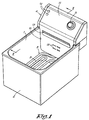
- figure 1 represents a view in perspective of a deep fat fryer according to the invention;
- figure 2 represents a cross-section according to line II-II in figure 1;
- figure 3 represents a view in perspective analogous to that of figure 1, but in respect to another form of embodiment of the deep fat fryer.
-
- The deep fat fryer represented in figures 1 and 2 substantially consists of an almost rectangular container made of stainless steel which, with its outward-bent edges, rests upon a
casing 2 which also is made of stainless steel, an electric immersion resistor 3 and aconnector box 4 which is provided at the container 1 and also forms the operating unit. - The immersion resistor 3 consists of a
heating bottom portion 5 and of two upward-directedportions 6, whereby the lowermost ends thereof are connected to the bottom portion and the uppermost ends thereof penetrate into theconnector box 4. These ends are fixed at theconnector box 4, and the opening through which they penetrate into the portion of theconnector box 4 hanging over the container 1, is sealed hermetically around theportions 6. - In this
connector box 4, the uppermost ends of theportions 6 are provided with electrical contacts 7, to which the ends of a power supply circuit are connected, which circuit, for simplicity's sake, is not represented in the figures. In this circuit, a thermostate and a temperature regulator, which can be set by means of anoperating button 8, are mounted. - This
connector box 4 bridges the edge of the container 1, and the underside of the portion situated at the exterior side of the container 1 is suspended in a removable manner at a leg of a hook 9 which is welded to the upper side of thehousing 2, or is slid by means of a pushing movement into a sled which is attached to thehousing 2. - At the interior side of the container 1, the
portions 6 of the immersion resistor 3 are practically completely covered by aprotective wall 10 which, in the represented example, has the form of a plate which, at its lower end, extends up to a small distance to thebottom portion 5 of the immersion resistor 3 and, at the top, is prolonged with aplate portion 11 and runs through over theoperating unit 4, even up to the rear wall thereof. - The width of the
protective wall 10 inside the container 1 is equal to the width of the container 1, such that above thebottom portion 5 the entire container wall, in front of which theportions 6 of the immersion resistor 3 are situated, is covered. Above the container 1, the width of theplate portion 11 is somewhat larger, such that the upper side of theoperating unit 4 is completely covered by thisplate portion 11, with the exeption of a small edge at both extremities. - The
operating button 8 is situated above thisplate portion 11, and twowindows 12 are provided in thisplate portion 11, opposite to lights which are switched into the power supply circuit. - At its side which is directed towards the interior side of the container 1, the
protective wall 10 at the top comprises ahook 13 for suspending thebasket 14 of the deep fat fryer above the frying oil, for example, for letting the fried products drop off. Thisbasket 14 is only represented in figure 2 and in dash-dot line. - The
protective wall 10 does not reduce the useful space of the container 1, in consideration of the fact that thebasket 14, due to theportions 6 of the immersion resistor 3, can not be larger than represented. - As the
hook 13 for thisbasket 14 is provided at theprotective wall 10 instead of the wall of the container, the construction of this container 1 is simplified. - Beneath the
hook 13, theprotective wall 10 is provided with twolevel indications 15 consisting of stripes. Next to the lowermost stripe, MIN is indicated, and next to the uppermost stripe, MAX. These stripes and letters can be formed by stamped portions in theprotective cover 10, such that they form a protruding relief towards the interior of the container 1. - The
protective wall 10 prevents dirt from adhering to the wall behind theportions 6 and to theseportions 6, and remainders of fried products or crumbs or such from accumulating between or behind theportions 6, where they are difficult to remove. - The container 1 and the immersion resistor therefore can be kept clean for a longer period of time and are easier to clean.
- Moreover, the
portions 6 are kept out of view, which enhances the appearance of the deep fat fryer. - The
protective wall 10, together with theconnector box 4 and the immersion resistor 3, is removed from the container 1 when this container 1 has to be cleaned and/or the frying oil has to be exchanged. - The
protective wall 10 does not necessarily have to be prolonged by aplate portion 11. It can be fixed with its upper side to the underside of the portion of theconnector box 4 which is situated above the interior side of the container 1. - As the dirt, in the first place, accumulates at the height of the level of the frying fat or the frying oil and higher, the
protective wall 10 not necessarily has to extend up to thebottom portion 5 of the immersion resistor 3, and it may suffice that it extends up to under the lowest fat or oil level. Also for esthetic reasons, it is, however, recommended that thisprotective wall 10 extends as low as possible. - The form of embodiment represented in figure 3 differs from the form of embodiment described in the aforegoing in that the deep fat fryer comprises a
cover 16 with afilter 17 which is fixed at theconnector box 4 in a hinged manner, but also in a removable manner. - To this aim, this
cover 16 comprises twohinge plates 18 which extend over the rearmost edge and are connected to the rest of thecover 16 in a springy manner. - At the top and at the side of the container 1, the connector box has an upward-directed
flat portion 19, into which twoslots 20 for theaforementioned hinge plates 18 give out. - The rearmost edge of the
cover 16 and theedge 21 of theconnector box 4, which latter edge is situated beneath thisportion 19, match in their form and, in the given example, are flat. - The
hinge plates 18 which, when thecover 16 is removed from the container 1, as represented in figure 3, by means of built-in springs are in the position in which they extend in the prolongation of thecover 16, are provided, with thecover 16 in vertical position, in theslots 20, after which thecover 16 can be tilted down. - In closed position, this
cover 16 fits precisely against the outward-bent edges of the container 1, except at the side of theconnector box 4, where the edge of thecover 16 fits precisely against the edge of thisconnector box 4. - If this
connector box 4, as represented in figure 3, is covered with theplate portion 11 adjoining theprotective wall 10, then the cover fits against thisplate portion 11. - In a variant, the
protective wall 10 is not prolonged by means of aplate portion 11, whereby then thecover 16 in closed position adjoins the uncovered side of theconnector box 4. - Possibly, the
cover 16 may also adjoin theflat portion 19. - The
protective wall 10 does not necessarily have to be flat and does not necessarily have to extend over the entire width of the container 1. It can, for example, adjoin the container wall with bent portions at opposite sides of theportions 6. - The invention is in no way limited to the forms of embodiment described heretofore, on the contrary may such deep fat fryer be realized in various variants while still remaining within the scope of the invention.
Claims (12)
- Electric deep fat fryer comprising a container (1), an immersion resistor (3) in this container (1), and a connector box (4) to which the immersion resistor (3) is attached and in which this immersion resistor (3) is connected to the power supply, characterized in that it comprises a protective wall (10) which is fixed at the connector box (4) and which extends at the interior side of the container (1) along the upward-directed portions (6) of the immersion resistor (3) connected to said connector box (4), such that these portions (6) are covered at least at the top.
- Deep fat fryer according to claim 1, characterized in that the protective wall (10) extends up to almost against the bottom portion (5) of the immersion resistor (3) extending above the bottom of the container (1), and that therefore the aforementioned portions (6) of said immersion resistor (3) are covered almost completely by the protective wall (10).
- Deep fat fryer according to claim 1 or 2, characterized in that the connector box (4) partially is situated above the interior side of the container (1), such that the upward-extending portions (6) of the immersion resistor (3) penetrate at the underside into the overhanging portion of the connector box (4).
- Deep fat fryer according to any of the preceding claims, characterized in that the protective wall (10) is a plate.
- Deep fat fryer according to any of the preceding claims, characterized in that the protective wall (10) is prolonged by a portion (11) which extends up to on top of the housing (13).
- Deep fat fryer according to claims 4 and 5, characterized in that the protective wall (10) with a plate portion (11) smoothly continues up to over the connector box (4).
- Deep fat fryer according to any of the preceding claims, characterized in that the protective wall (10) extends over almost the entire width of the container wall, in front of which the upward-extending portions (6) of the immersion resistor (3) are situated.
- Deep fat fryer according to any of the preceding claims, characterized in that the protective wall (10) is provided with a hook (13) or 'such at the upper edge of the container (1), at which hook or such a possible basket (14) may be suspended.
- Deep fat fryer according to any of the preceding claims, characterized in that the protective wall (10) is provided with at least one level indication (15), preferably a minimum and a maximum level indication (15).
- Deep fat fryer according to any of the preceding claims, characterized in that the protective wall (10) is made of metal, in particular of stainless steel.
- Deep fat fryer according to claim 3, characterized in that it comprises a cover (16) with a filter (17) which is fixed at the connector box (4) in a hinged manner and that the from of the edge of the cover (16), which in closed position is situated opposite to the connector box (4), is adapted to the corresponding opposite edge (21) of the connector box (4), which edge either or not is covered by a prolongation of the protective wall (10).
- Deep fat fryer according to claim 11, characterized in that the cover (16) can be removed from the connector box (4) and that this latter to this aim is provided with two openings (20), for example, slots, which are open towards the top and in which hinge plates (18) of the cover (16) are inserted in a removable manner.
Applications Claiming Priority (2)
| Application Number | Priority Date | Filing Date | Title |
|---|---|---|---|
| BE9900069A BE1012458A3 (en) | 1999-02-02 | 1999-02-02 | Electric fryer. |
| BE9900069 | 1999-02-02 |
Publications (2)
| Publication Number | Publication Date |
|---|---|
| EP1025788A1 true EP1025788A1 (en) | 2000-08-09 |
| EP1025788B1 EP1025788B1 (en) | 2003-08-20 |
Family
ID=3891733
Family Applications (1)
| Application Number | Title | Priority Date | Filing Date |
|---|---|---|---|
| EP00200301A Expired - Lifetime EP1025788B1 (en) | 1999-02-02 | 2000-01-31 | Electric deep fat fryer |
Country Status (4)
| Country | Link |
|---|---|
| EP (1) | EP1025788B1 (en) |
| AT (1) | ATE247411T1 (en) |
| BE (1) | BE1012458A3 (en) |
| DE (1) | DE60004576T2 (en) |
Cited By (5)
| Publication number | Priority date | Publication date | Assignee | Title |
|---|---|---|---|---|
| WO2003030697A1 (en) * | 2001-10-02 | 2003-04-17 | 3Rd Angle (U.K.) Ltd. | Deep fryer |
| WO2004039229A1 (en) * | 2002-10-31 | 2004-05-13 | Ian Geoffrey Wilson | Deep frying appliance |
| USD496822S1 (en) | 2002-07-18 | 2004-10-05 | 3Rd Angle (U.K.) Ltd. | Deep fat fryer |
| USD523686S1 (en) * | 2003-10-24 | 2006-06-27 | 3Rd Angle (U.K.) Ltd. | Deep fryer |
| JP2015083078A (en) * | 2013-10-25 | 2015-04-30 | ホシザキ電機株式会社 | Fryer |
Citations (3)
| Publication number | Priority date | Publication date | Assignee | Title |
|---|---|---|---|---|
| US2448634A (en) * | 1940-05-20 | 1948-09-07 | Moffats Ltd | Electric heating apparatus |
| US4468556A (en) * | 1982-08-09 | 1984-08-28 | Emerson Electric Co. | Electric heating elements |
| FR2668913A1 (en) * | 1990-11-14 | 1992-05-15 | Rosinox | System for assembling the heating elements of an electric fryer |
-
1999
- 1999-02-02 BE BE9900069A patent/BE1012458A3/en not_active IP Right Cessation
-
2000
- 2000-01-31 EP EP00200301A patent/EP1025788B1/en not_active Expired - Lifetime
- 2000-01-31 DE DE60004576T patent/DE60004576T2/en not_active Expired - Fee Related
- 2000-01-31 AT AT00200301T patent/ATE247411T1/en not_active IP Right Cessation
Patent Citations (3)
| Publication number | Priority date | Publication date | Assignee | Title |
|---|---|---|---|---|
| US2448634A (en) * | 1940-05-20 | 1948-09-07 | Moffats Ltd | Electric heating apparatus |
| US4468556A (en) * | 1982-08-09 | 1984-08-28 | Emerson Electric Co. | Electric heating elements |
| FR2668913A1 (en) * | 1990-11-14 | 1992-05-15 | Rosinox | System for assembling the heating elements of an electric fryer |
Cited By (8)
| Publication number | Priority date | Publication date | Assignee | Title |
|---|---|---|---|---|
| WO2003030697A1 (en) * | 2001-10-02 | 2003-04-17 | 3Rd Angle (U.K.) Ltd. | Deep fryer |
| WO2003030698A1 (en) * | 2001-10-02 | 2003-04-17 | 3Rd Angle (U.K) Ltd. | Deep-fat fryer |
| US6998581B2 (en) | 2001-10-02 | 2006-02-14 | 3Rd Angle (U.K.) Ltd. | Deep fryer |
| USD496822S1 (en) | 2002-07-18 | 2004-10-05 | 3Rd Angle (U.K.) Ltd. | Deep fat fryer |
| WO2004039229A1 (en) * | 2002-10-31 | 2004-05-13 | Ian Geoffrey Wilson | Deep frying appliance |
| US7211770B2 (en) | 2002-10-31 | 2007-05-01 | Ian Geoffrey Wilson | Deep frying appliance |
| USD523686S1 (en) * | 2003-10-24 | 2006-06-27 | 3Rd Angle (U.K.) Ltd. | Deep fryer |
| JP2015083078A (en) * | 2013-10-25 | 2015-04-30 | ホシザキ電機株式会社 | Fryer |
Also Published As
| Publication number | Publication date |
|---|---|
| DE60004576D1 (en) | 2003-09-25 |
| DE60004576T2 (en) | 2004-06-03 |
| ATE247411T1 (en) | 2003-09-15 |
| BE1012458A3 (en) | 2000-11-07 |
| EP1025788B1 (en) | 2003-08-20 |
Similar Documents
| Publication | Publication Date | Title |
|---|---|---|
| US6399925B1 (en) | Versatile surface heating cartridge for cooking appliance | |
| AU2003300872B2 (en) | Barbecue grill and support frame assembly | |
| US6742444B1 (en) | Electric cooking apparatus | |
| US2903549A (en) | Barbecue unit | |
| EP0696430A1 (en) | Multi-function electric home appliance | |
| RU2003135542A (en) | FRY ELECTRIC INSTALLER CONTAINING A BOWL RELATED TO A LIQUID DRAINING DEVICE | |
| EP0587300B1 (en) | Fryers | |
| US7098427B2 (en) | Device for filtration of the frying bath in an electric fryer having an immersed heating resistor | |
| EP1025788B1 (en) | Electric deep fat fryer | |
| US20090032009A1 (en) | Grill With Improved-Configuration Grease Collecting Box | |
| EP1195122B1 (en) | Deep frying apparatus and method | |
| JP2016013263A (en) | Cooker | |
| CN101091625A (en) | Household appliance with storage housing | |
| US5740720A (en) | Multiple-doughnut fryer system | |
| US3433930A (en) | Broiler with removable heating cartridge | |
| JP6374710B2 (en) | Cooker | |
| GB2117627A (en) | Improvements in or relating to electric toasters | |
| JP2000157424A (en) | Electric roaster | |
| CN218390805U (en) | Seasoning box and frying and baking device | |
| GB2424360A (en) | Cooking apparatus | |
| KR0121912Y1 (en) | Toaster with Fry Pan | |
| CA2391067C (en) | Versatile surface heating cartridge for cooking appliance | |
| JPS6221250Y2 (en) | ||
| KR200189537Y1 (en) | Gas burner | |
| JP2506888B2 (en) | Electric stove |
Legal Events
| Date | Code | Title | Description |
|---|---|---|---|
| PUAI | Public reference made under article 153(3) epc to a published international application that has entered the european phase |
Free format text: ORIGINAL CODE: 0009012 |
|
| AK | Designated contracting states |
Kind code of ref document: A1 Designated state(s): AT BE CH CY DE DK ES FI FR GB GR IE IT LI LU MC NL PT SE |
|
| AX | Request for extension of the european patent |
Free format text: AL;LT;LV;MK;RO;SI |
|
| AKX | Designation fees paid |
Free format text: AT BE CH CY DE DK ES FI FR GB GR IE IT LI LU MC NL PT SE |
|
| 17P | Request for examination filed |
Effective date: 20010126 |
|
| RBV | Designated contracting states (corrected) |
Designated state(s): AT BE CH CY DE DK ES FI FR GB GR IE IT LI LU MC NL PT SE |
|
| GRAH | Despatch of communication of intention to grant a patent |
Free format text: ORIGINAL CODE: EPIDOS IGRA |
|
| GRAS | Grant fee paid |
Free format text: ORIGINAL CODE: EPIDOSNIGR3 |
|
| GRAA | (expected) grant |
Free format text: ORIGINAL CODE: 0009210 |
|
| RIN1 | Information on inventor provided before grant (corrected) |
Inventor name: VAN RATINGEN, JOS |
|
| AK | Designated contracting states |
Designated state(s): AT BE CH CY DE DK ES FI FR GB GR IE IT LI LU MC NL PT SE |
|
| PG25 | Lapsed in a contracting state [announced via postgrant information from national office to epo] |
Ref country code: IT Free format text: LAPSE BECAUSE OF FAILURE TO SUBMIT A TRANSLATION OF THE DESCRIPTION OR TO PAY THE FEE WITHIN THE PRESCRIBED TIME-LIMIT;WARNING: LAPSES OF ITALIAN PATENTS WITH EFFECTIVE DATE BEFORE 2007 MAY HAVE OCCURRED AT ANY TIME BEFORE 2007. THE CORRECT EFFECTIVE DATE MAY BE DIFFERENT FROM THE ONE RECORDED. Effective date: 20030820 Ref country code: CY Free format text: LAPSE BECAUSE OF FAILURE TO SUBMIT A TRANSLATION OF THE DESCRIPTION OR TO PAY THE FEE WITHIN THE PRESCRIBED TIME-LIMIT Effective date: 20030820 Ref country code: FI Free format text: LAPSE BECAUSE OF FAILURE TO SUBMIT A TRANSLATION OF THE DESCRIPTION OR TO PAY THE FEE WITHIN THE PRESCRIBED TIME-LIMIT Effective date: 20030820 |
|
| REG | Reference to a national code |
Ref country code: GB Ref legal event code: FG4D |
|
| REG | Reference to a national code |
Ref country code: CH Ref legal event code: EP |
|
| REG | Reference to a national code |
Ref country code: IE Ref legal event code: FG4D |
|
| REF | Corresponds to: |
Ref document number: 60004576 Country of ref document: DE Date of ref document: 20030925 Kind code of ref document: P |
|
| PG25 | Lapsed in a contracting state [announced via postgrant information from national office to epo] |
Ref country code: SE Free format text: LAPSE BECAUSE OF FAILURE TO SUBMIT A TRANSLATION OF THE DESCRIPTION OR TO PAY THE FEE WITHIN THE PRESCRIBED TIME-LIMIT Effective date: 20031120 Ref country code: GR Free format text: LAPSE BECAUSE OF FAILURE TO SUBMIT A TRANSLATION OF THE DESCRIPTION OR TO PAY THE FEE WITHIN THE PRESCRIBED TIME-LIMIT Effective date: 20031120 Ref country code: DK Free format text: LAPSE BECAUSE OF FAILURE TO SUBMIT A TRANSLATION OF THE DESCRIPTION OR TO PAY THE FEE WITHIN THE PRESCRIBED TIME-LIMIT Effective date: 20031120 |
|
| PG25 | Lapsed in a contracting state [announced via postgrant information from national office to epo] |
Ref country code: ES Free format text: LAPSE BECAUSE OF FAILURE TO SUBMIT A TRANSLATION OF THE DESCRIPTION OR TO PAY THE FEE WITHIN THE PRESCRIBED TIME-LIMIT Effective date: 20031201 |
|
| REG | Reference to a national code |
Ref country code: CH Ref legal event code: NV Representative=s name: DR. R.C. SALGO EUROPEAN PATENT ATTORNEY |
|
| PG25 | Lapsed in a contracting state [announced via postgrant information from national office to epo] |
Ref country code: PT Free format text: LAPSE BECAUSE OF FAILURE TO SUBMIT A TRANSLATION OF THE DESCRIPTION OR TO PAY THE FEE WITHIN THE PRESCRIBED TIME-LIMIT Effective date: 20040120 |
|
| PG25 | Lapsed in a contracting state [announced via postgrant information from national office to epo] |
Ref country code: MC Free format text: LAPSE BECAUSE OF NON-PAYMENT OF DUE FEES Effective date: 20040131 |
|
| PG25 | Lapsed in a contracting state [announced via postgrant information from national office to epo] |
Ref country code: IE Free format text: LAPSE BECAUSE OF NON-PAYMENT OF DUE FEES Effective date: 20040202 |
|
| PGFP | Annual fee paid to national office [announced via postgrant information from national office to epo] |
Ref country code: GB Payment date: 20040301 Year of fee payment: 5 |
|
| ET | Fr: translation filed | ||
| PLBE | No opposition filed within time limit |
Free format text: ORIGINAL CODE: 0009261 |
|
| STAA | Information on the status of an ep patent application or granted ep patent |
Free format text: STATUS: NO OPPOSITION FILED WITHIN TIME LIMIT |
|
| 26N | No opposition filed |
Effective date: 20040524 |
|
| REG | Reference to a national code |
Ref country code: IE Ref legal event code: MM4A |
|
| PGFP | Annual fee paid to national office [announced via postgrant information from national office to epo] |
Ref country code: FR Payment date: 20041203 Year of fee payment: 6 |
|
| PGFP | Annual fee paid to national office [announced via postgrant information from national office to epo] |
Ref country code: DE Payment date: 20050106 Year of fee payment: 6 |
|
| PGFP | Annual fee paid to national office [announced via postgrant information from national office to epo] |
Ref country code: CH Payment date: 20050110 Year of fee payment: 6 |
|
| PGFP | Annual fee paid to national office [announced via postgrant information from national office to epo] |
Ref country code: AT Payment date: 20050118 Year of fee payment: 6 |
|
| PG25 | Lapsed in a contracting state [announced via postgrant information from national office to epo] |
Ref country code: GB Free format text: LAPSE BECAUSE OF NON-PAYMENT OF DUE FEES Effective date: 20050131 |
|
| GBPC | Gb: european patent ceased through non-payment of renewal fee |
Effective date: 20050131 |
|
| PG25 | Lapsed in a contracting state [announced via postgrant information from national office to epo] |
Ref country code: FR Free format text: LAPSE BECAUSE OF NON-PAYMENT OF DUE FEES Effective date: 20060131 Ref country code: AT Free format text: LAPSE BECAUSE OF NON-PAYMENT OF DUE FEES Effective date: 20060131 Ref country code: CH Free format text: LAPSE BECAUSE OF NON-PAYMENT OF DUE FEES Effective date: 20060131 Ref country code: LI Free format text: LAPSE BECAUSE OF NON-PAYMENT OF DUE FEES Effective date: 20060131 |
|
| PG25 | Lapsed in a contracting state [announced via postgrant information from national office to epo] |
Ref country code: DE Free format text: LAPSE BECAUSE OF NON-PAYMENT OF DUE FEES Effective date: 20060801 |
|
| REG | Reference to a national code |
Ref country code: CH Ref legal event code: PL |
|
| REG | Reference to a national code |
Ref country code: FR Ref legal event code: ST Effective date: 20060929 |
|
| PGFP | Annual fee paid to national office [announced via postgrant information from national office to epo] |
Ref country code: LU Payment date: 20100203 Year of fee payment: 11 |
|
| PGFP | Annual fee paid to national office [announced via postgrant information from national office to epo] |
Ref country code: NL Payment date: 20100131 Year of fee payment: 11 Ref country code: BE Payment date: 20100303 Year of fee payment: 11 |
|
| BERE | Be: lapsed |
Owner name: *VAN RATINGEN N.V. Effective date: 20110131 |
|
| REG | Reference to a national code |
Ref country code: NL Ref legal event code: V1 Effective date: 20110801 |
|
| PG25 | Lapsed in a contracting state [announced via postgrant information from national office to epo] |
Ref country code: BE Free format text: LAPSE BECAUSE OF NON-PAYMENT OF DUE FEES Effective date: 20110131 |
|
| PG25 | Lapsed in a contracting state [announced via postgrant information from national office to epo] |
Ref country code: NL Free format text: LAPSE BECAUSE OF NON-PAYMENT OF DUE FEES Effective date: 20110801 |
|
| PG25 | Lapsed in a contracting state [announced via postgrant information from national office to epo] |
Ref country code: LU Free format text: LAPSE BECAUSE OF NON-PAYMENT OF DUE FEES Effective date: 20110131 |