EP1025774A2 - Seat belt buckle - Google Patents
Seat belt buckle Download PDFInfo
- Publication number
- EP1025774A2 EP1025774A2 EP00100594A EP00100594A EP1025774A2 EP 1025774 A2 EP1025774 A2 EP 1025774A2 EP 00100594 A EP00100594 A EP 00100594A EP 00100594 A EP00100594 A EP 00100594A EP 1025774 A2 EP1025774 A2 EP 1025774A2
- Authority
- EP
- European Patent Office
- Prior art keywords
- ejector
- blocking device
- securing
- locking
- seat belt
- Prior art date
- Legal status (The legal status is an assumption and is not a legal conclusion. Google has not performed a legal analysis and makes no representation as to the accuracy of the status listed.)
- Granted
Links
Images


Classifications
-
- A—HUMAN NECESSITIES
- A44—HABERDASHERY; JEWELLERY
- A44B—BUTTONS, PINS, BUCKLES, SLIDE FASTENERS, OR THE LIKE
- A44B11/00—Buckles; Similar fasteners for interconnecting straps or the like, e.g. for safety belts
- A44B11/25—Buckles; Similar fasteners for interconnecting straps or the like, e.g. for safety belts with two or more separable parts
- A44B11/2503—Safety buckles
- A44B11/2507—Safety buckles actuated by a push-button
- A44B11/2523—Safety buckles actuated by a push-button acting parallel to the main plane of the buckle and in the same direction as the fastening action
-
- Y—GENERAL TAGGING OF NEW TECHNOLOGICAL DEVELOPMENTS; GENERAL TAGGING OF CROSS-SECTIONAL TECHNOLOGIES SPANNING OVER SEVERAL SECTIONS OF THE IPC; TECHNICAL SUBJECTS COVERED BY FORMER USPC CROSS-REFERENCE ART COLLECTIONS [XRACs] AND DIGESTS
- Y10—TECHNICAL SUBJECTS COVERED BY FORMER USPC
- Y10T—TECHNICAL SUBJECTS COVERED BY FORMER US CLASSIFICATION
- Y10T24/00—Buckles, buttons, clasps, etc.
- Y10T24/45—Separable-fastener or required component thereof [e.g., projection and cavity to complete interlock]
- Y10T24/45225—Separable-fastener or required component thereof [e.g., projection and cavity to complete interlock] including member having distinct formations and mating member selectively interlocking therewith
- Y10T24/45602—Receiving member includes either movable connection between interlocking components or variable configuration cavity
- Y10T24/45623—Receiving member includes either movable connection between interlocking components or variable configuration cavity and operator therefor
-
- Y—GENERAL TAGGING OF NEW TECHNOLOGICAL DEVELOPMENTS; GENERAL TAGGING OF CROSS-SECTIONAL TECHNOLOGIES SPANNING OVER SEVERAL SECTIONS OF THE IPC; TECHNICAL SUBJECTS COVERED BY FORMER USPC CROSS-REFERENCE ART COLLECTIONS [XRACs] AND DIGESTS
- Y10—TECHNICAL SUBJECTS COVERED BY FORMER USPC
- Y10T—TECHNICAL SUBJECTS COVERED BY FORMER US CLASSIFICATION
- Y10T24/00—Buckles, buttons, clasps, etc.
- Y10T24/45—Separable-fastener or required component thereof [e.g., projection and cavity to complete interlock]
- Y10T24/45225—Separable-fastener or required component thereof [e.g., projection and cavity to complete interlock] including member having distinct formations and mating member selectively interlocking therewith
- Y10T24/45602—Receiving member includes either movable connection between interlocking components or variable configuration cavity
- Y10T24/45623—Receiving member includes either movable connection between interlocking components or variable configuration cavity and operator therefor
- Y10T24/45639—Receiving member includes either movable connection between interlocking components or variable configuration cavity and operator therefor including pivotally connected element on receiving member
- Y10T24/45644—Receiving member includes either movable connection between interlocking components or variable configuration cavity and operator therefor including pivotally connected element on receiving member for shifting pivotally connected interlocking component
-
- Y—GENERAL TAGGING OF NEW TECHNOLOGICAL DEVELOPMENTS; GENERAL TAGGING OF CROSS-SECTIONAL TECHNOLOGIES SPANNING OVER SEVERAL SECTIONS OF THE IPC; TECHNICAL SUBJECTS COVERED BY FORMER USPC CROSS-REFERENCE ART COLLECTIONS [XRACs] AND DIGESTS
- Y10—TECHNICAL SUBJECTS COVERED BY FORMER USPC
- Y10T—TECHNICAL SUBJECTS COVERED BY FORMER US CLASSIFICATION
- Y10T24/00—Buckles, buttons, clasps, etc.
- Y10T24/45—Separable-fastener or required component thereof [e.g., projection and cavity to complete interlock]
- Y10T24/45225—Separable-fastener or required component thereof [e.g., projection and cavity to complete interlock] including member having distinct formations and mating member selectively interlocking therewith
- Y10T24/45602—Receiving member includes either movable connection between interlocking components or variable configuration cavity
- Y10T24/45623—Receiving member includes either movable connection between interlocking components or variable configuration cavity and operator therefor
- Y10T24/4566—Receiving member includes either movable connection between interlocking components or variable configuration cavity and operator therefor including slidably connected and guided element on receiving member
- Y10T24/45665—Receiving member includes either movable connection between interlocking components or variable configuration cavity and operator therefor including slidably connected and guided element on receiving member for shifting pivotally connected interlocking component
-
- Y—GENERAL TAGGING OF NEW TECHNOLOGICAL DEVELOPMENTS; GENERAL TAGGING OF CROSS-SECTIONAL TECHNOLOGIES SPANNING OVER SEVERAL SECTIONS OF THE IPC; TECHNICAL SUBJECTS COVERED BY FORMER USPC CROSS-REFERENCE ART COLLECTIONS [XRACs] AND DIGESTS
- Y10—TECHNICAL SUBJECTS COVERED BY FORMER USPC
- Y10T—TECHNICAL SUBJECTS COVERED BY FORMER US CLASSIFICATION
- Y10T24/00—Buckles, buttons, clasps, etc.
- Y10T24/45—Separable-fastener or required component thereof [e.g., projection and cavity to complete interlock]
- Y10T24/45225—Separable-fastener or required component thereof [e.g., projection and cavity to complete interlock] including member having distinct formations and mating member selectively interlocking therewith
- Y10T24/45602—Receiving member includes either movable connection between interlocking components or variable configuration cavity
- Y10T24/45623—Receiving member includes either movable connection between interlocking components or variable configuration cavity and operator therefor
- Y10T24/4566—Receiving member includes either movable connection between interlocking components or variable configuration cavity and operator therefor including slidably connected and guided element on receiving member
- Y10T24/4567—Receiving member includes either movable connection between interlocking components or variable configuration cavity and operator therefor including slidably connected and guided element on receiving member for shifting slidably connected and guided, nonself-biasing, interlocking component
Definitions
- This invention relates to a buckle for a seat belt according to the preamble of claim 1.
- the known buckle comprises a guide channel inside a buckle frame, into which a tongue connected to a seat belt can be inserted.
- An ejector is guided in the guide channel, upon which ejector is acting an ejector spring in the ejection direction, opposite to the insertion direction.
- a locking element is moveably mounted on the buckle frame, which locking element can be moved into a locking position for locking the tongue introduced into the guide channel and into a release position for releasing the tongue.
- a securing element is moveably mounted on the buckle frame, which securing element can be moved into a securing position for holding the locking element in its locking position and into a release position for releasing the locking element. Furthermore, a support is provided, which holds the securing element in the securing position upon excessive acceleration and/or deceleration. This ensures that the securing element remains in its securing position, even during high acceleration and/or deceleration of the buckle, such as, for example, upon retensioning of the buckle via a belt tightener acting upon the buckle. The locking element is thereby secured in its locking position, so that the desired tightening of the belt, which is held in the buckle, is obtained.
- the securing element is held in the securing position in the acceleration phase of the retensioning procedure.
- a compensating mass which is linearly guided in the guide channel on the buckle frame, acts upon the securing element through a lever arm and the support, holding the securing element in the securing position.
- the ejector is supported through the ejector spring on the compensating mass.
- An actuating lever which is formed as an angle lever, is pivotably mounted on the securing element, such that the insertion movement of the tongue can be transmitted through the actuating lever onto the locking element in order to ensure its movement into the locking position.
- a compensating mass mounted on a lever arm acts through a support (plunger) upon the securing element in the acceleration phase of the retensioning procedure.
- the effect of the lever on which the compensating mass is mounted is cancelled due to the inertia of the compensating mass which tends to continue its movement in the direction of the acceleration phase of the retensioning procedure, such that an absolutely secure holding of the securing element in the securing position by means of the compensating mass is no longer ensured.
- a blocking device mounted on or connected to the securing element which blocking device may be designed as an angle lever, as known from EP 0 777 984 A2, is moved into a blocking position when the locking element is in the locking position.
- the securing element is thus held in its securing position, against a movement in the release position.
- the blocking device is thereby held in the blocking position by the ejector.
- the blocking device When the blocking device is designed as an angle lever, it has two functions. Upon introduction of the buckle tongue, the blocking device in the same manner as the actuating lever known from EP 0 777 984 A2, is rotated by the ejector mass, such that the locking element is pushed into its final locking position. The other function consists in holding the blocking device in its blocking position by the ejector. The securing element is thereby held against movement in the release position. The locking element is thus secured in its locking position.
- the blocking device is located in its blocking position, upon acceleration of the buckle, for example upon a retensioning procedure, as well as upon deceleration of this accelerated movement.
- the invention ensures that the blocking device is held in its blocking position. This may be achieved by appropriately designing the blocking device contour on the ejector.
- the longitudinal extension of the blocking device contour is dimensioned such that the blocking device remains engaged with the blocking device contour throughout the movement of the ejector from its normal position in the locking position to a rear abutment position, and is thus held in the blocking position.
- the blocking device When the blocking device is designed as an angle lever, one of the two lever arms may engage the ejector, especially the blocking device contour on the ejector.
- the other lever arm may be held in abutment with a buckle part, preferably with the locking element in its locking position, such as to prevent a movement into the release position.
- the blocking device is held in this blocking position between this abutment and the ejector, especially the blocking device contour on the ejector. Since the blocking device is mounted on the securing element or connected thereto, the securing element, which may be designed as a peg in a known manner, is held in its securing position.
- a deformable part may be provided on the ejector.
- the deformable part acts as an energy absorbing means upon impact of the ejector, as a result of its inertia, on a frame-fixed abutment, which delimits the backward movement of the ejector. Bounce movements of the other buckle components, which may occur as a result of the hard impact of the ejector, are thus prevented.
- the securing element may be spring biased.
- a spring may be provided, which is linearly guided and supported on the buckle frame. The spring bias is directed such that in the locking position the securing element is pressed against an abutment on the buckle frame.
- the securing element is pressed against a holding surface on the locking element, whereby the locking element is held in its unlocked position inside the buckle frame.
- the invention provides an impact-resistant seatbelt buckle, comprising fewer components.
- a secured locking of the locking element, engaging the tongue, is ensured upon excessive acceleration, as for example upon retensioning of the buckle, as well as jerky deceleration at the end of the retensioning movement.
- a buckle frame is substantially formed by an upper plate 1 and a lower plate 2. The two plates are interconnected via connecting bolt 26.
- a guide channel 3 is formed between the upper plate 1 and the lower plate 2.
- An ejector 5 is guided in the guide channel 3 such as to be longitudinally movable.
- the ejector 5 is biased in the ejection direction of a tongue 4, by an ejector spring 6, which is supported on an abutment 22 defined on the buckle frame.
- the tongue 4 is connected to a seat belt (not shown) in a known manner.
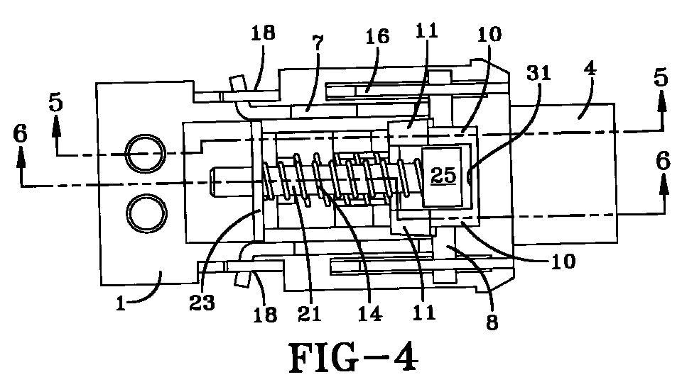
- the tongue 4 is introduced in the guide channel 3, whereupon the ejector 5 is pushed against the force of the ejector spring 6 in a position shown in FIG.5.
- a locking element 7, with an engagement part 30, engages a locking recess 27 of the tongue 4.
- This locking position is shown in FIGS. 2 to 6.
- the locking element 7 is secured by a peg-like designed securing element 8.
- the securing element 8 is longitudinally guided in longitudinal slots 17 on the frame members 16. This longitudinal guiding is substantially parallel to the guide channel 3.
- the spring support 23 can also be formed on the lower plate 2.
- the bias spring 14, which is designed as a compression spring (helical compression spring), comprises a rod-like linear guiding means 21.
- the helical compression spring (bias spring 14) is wound around said guiding means.
- the linear guiding means 21 comprises an engagement part 25, which engages the securing element 8.
- the linear guiding means 21 is guided in a guide opening 24 of the spring support 23. This ensures that the bias spring 14 is kept in its linear shape with constant effective direction, in the respective positions of the securing element 8. Furthermore, the rod-like design of the linear guiding means 21 in this embodiment prevents breaking out or kinking of the bias spring 14 in all operative positions, thus always ensuring the desired securing and holding function of the securing element 8.
- the securing element 8 In the locking position, the securing element 8 is in contact with securing surfaces 28 (FIG.1) at the upper side of the locking element 7.
- the securing element 8 is held in the leading position in the guide slots 17 by means of the bias spring 14, in which position the securing element 8 is in contact with the ends of the guide slot 17.
- These ends of the guide slot form abutments 15 on the buckle frame.
- the width of the guide slot 17 is dimensioned slightly larger than the diameter of the securing element 8, such that the securing element 8 is displaceably guided in the slots on the buckle frame.
- the securing element 8 In the shown locking position, the securing element 8 is in contact with the abutments 15 at the front ends of the guide slots 17. This ensures that the locking element 7 is unable to move upwards, but is instead kept engaged with the locking recess 27 of the tongue 4.
- a blocking device 9 is pivotably mounted on the peg-like securing element 8.
- the blocking device 9 is designed as an angle lever comprising first lever arms 10, which may be interconnected through a connecting link 31, and second lever arms 11.
- the lever arms 10, 11 are at an angle of about 90°.
- the ejector 5 in Figs. 4 to 6 is displaced from right to left, i.e. to the backward end of the guide channel 3.
- blocking device contours 12, formed on the ejector 5 engage the lever arms 11.
- the blocking device 9 is thus pivoted clockwise, whereby an actuating edge at the lower side of the connecting link 31 presses on the upper side e.g.
- the blocking device 9 rests with its second lever arms 11 on the blocking device contour 12 of the ejector 5, as shown in FIG.5. Furthermore the blocking device 9 overlaps via its first lever arms 10 the upper edge 29, which extends transversely between the two securing surfaces 28 and over an engagement part 30, and is in contact with the locking element 7 in the region of the edge 29. A securing and fixing against any movement of the blocking device 9 on the buckle frame is hereby ensured. Because the securing element 8 is connected to the blocking device 9, a fixing of the securing element on the buckle frame is also ensured. A movement of the blocking device 9 and of the securing element 8 inside the guide slot 17 from the illustrated right position into the left position, i.e. in the unlocking direction, is rendered impossible.
- the blocking device 9 In the blocking position the blocking device 9, with its two first lever arms 10, is in contact with the locking element 7, which is in the locking position.
- the blocking device contour 12 on the ejector 5 is dimensioned such as to keep the blocking device 9 and the securing element 8 in a fixed blocking position or securing position, in the acceleration phase of the buckle as well as in the deceleration phase after the acceleration.
- the buckle is moved from right to left in FIG.4 to FIG.6 upon retensioning of the buckle.
- the ejector 5 and a push button 20 remain in the positions shown in FIG.4 and FIG.5.
- the second lever arms 11 of the blocking device 9 rest on the rearward section of the blocking device contour 12, whereby the blocking device 9 is kept in said blocking position, shown in FIG.5.
- a deceleration occurs on completion of the retensioning movement, whereby the ejector 5 is moved out of its normal position, on the right in FIG.5, to the left into the locking position of the buckle, until it impacts against the frame-fixed abutment 22.
- the length of the blocking device contour 12 is dimensioned such that it remains engaged with the second lever arms 11 of the blocking device 9, thus maintaining the blocking position of blocking device 9 and thereby the securing position of the securing element 8, as shown in FIG.6. This ensures that the locking element 7, with its engagement part 30, is securely held in the locking recess 27 of the tongue 4.
- the push button 20 Upon deceleration of the accelerated leftward directed movement, as for example on completion of the retensioning movement, the push button 20 is also moved to the left as a result of its inertia, whereby however a raising of the locking element 7 is prevented, since the blocking device 9 and the securing element are kept in the blocking or securing position respectively, as explained above.
- the reason for this is the fact that the blocking device 9 with its second lever arms 11 is kept engaged with the blocking device contour 12 on the ejector 5, as shown in FIG.6.
- a deformable part 13 may be provided on the ejector 5. Upon impact of the ejector 5 on the frame-fixed abutment 22, this part 13 is deformed, whereby energy is dissipated. On impact of the ejector 5 on the abutment 22, shock absorption is obtained. Bounce movements of the other functional parts of the buckle, which may result from the hard impact of the ejector 5 on the abutment 22, are hereby prevented.
- the buckle can be brought back in its unlocking position, by means of the push button 20.
- the push button by means of an abutment or an interlocking fit provides for the displacement of the securing element 8 to the left in Fig.4 to FIG.6, whereby the blocking device 9 with its second lever arms 11 detaches from the blocking device contour 12 and the securing element 8 is shifted into its final released position.
- the locking element 7 is pivotably mounted on the buckle frame, in the drag bearing 18, which can be designed in the same way as known from EP 0 777 984 A2. This allows the movement of the locking element 7 between an unlocking position and a locking position.
Landscapes
- Buckles (AREA)
- Automotive Seat Belt Assembly (AREA)
Abstract
Description
- 1
- upper plate
- 2
- lower plate
- 3
- guide channel
- 4
- tongue
- 5
- ejector
- 6
- ejector spring
- 7
- locking element
- 8
- securing element
- 9
- blocking device
- 10
- first lever arm
- 11
- second lever arm
- 12
- blocking device contour
- 13
- deformable part
- 14
- bias spring
- 15
- abutment
- 16
- frame member
- 17
- guide slot
- 18
- drag bearing
- 19
- holding surface
- 20
- push-button
- 21
- linear guiding means
- 22
- abutment
- 23
- spring support
- 24
- guide opening
- 25
- engagement part
- 26
- connecting bolt
- 27
- locking recess
- 28
- securing surfaces
- 29
- upper edge
- 30
- engagement part
- 31
- connecting link
Claims (9)
- Seat belt buckle comprising:a guide channel (3) formed in a buckle frame (1, 2), into which guide channel a tongue connected to the seat belt can be inserted,an ejector (5) guided in a guide channel (3), upon which ejector an ejector spring (6) is acting in the ejection direction opposite to the insertion direction,a locking element (7) mounted on a buckle frame (1, 2), which locking element can be moved out of an unlocking position into a locking position, in order to lock the tongue (4) introduced into the guide channel (3), anda securing element (8), which can be moved into a securing position, for holding the locking element (7) in the locking position, and into a release position for releasing the locking element,
characterized in that:a blocking device (9) is provided on the securing element (8), which blocking device is moved into a blocking position, when the locking element (7) is in the locking position, wherein the securing element (8) is firmly held in the securing position by the blocking device (9) against a movement into the release position, and the blocking device (9) is thereby held in the blocking position by the ejector (5). - The seat belt buckle according to claim 1, characterized in that in its blocking position, the blocking device (9) is kept in an abutment position on a buckle part by the ejector (5), whereby a movement of the securing element (8) into the release position is rendered impossible.
- The seat belt buckle according to claim 1 or 2, characterized in that the blocking device (9) is in contact with the locking element (7) in the blocking position.
- The seat belt buckle according to one of claims 1 to 3, characterized in that on the ejector (5) there is provided a blocking device contour (12), which engages the blocking device (9) upon an accelerated movement in the insertion direction as well as upon a deceleration following this accelerated movement and holds said blocking device in the blocking position.
- The seat belt buckle according to one of claims 1 to 4 characterized in that the blocking device (9) is designed as an angle lever comprising a first and a second lever arm (10, 11), pivotable about an axis formed on the securing element (8), whereby, in the blocking position, the first lever arm (10) is in contact with the buckle part, in particular the locking element (7), and the second lever arm (11) is in contact with the ejector (5), in particular the blocking device contour (12).
- The seat belt buckle according to any one of claims 1 to 5, characterized in that a deformable part (13) is provided on the ejector (5), which part is deformable upon deceleration of the accelerated movement in the insertion direction of the buckle.
- The seat belt buckle according to any one of claims 1 to 6, characterized in that a bias spring (14) engages the securing element (8), whereby the locking element (7) is held in its unlocking position.
- The seat belt buckle according to any one of claims 1 to 7, characterized in that in its securing position the securing element (8) is pressed by the bias spring (14) against an abutment (15) on the buckle frame (1, 2).
- The seat belt buckle according to any one of claims 1 to 8, characterized in that a linear guiding means (21) for the bias spring (14) is provided.
Applications Claiming Priority (2)
| Application Number | Priority Date | Filing Date | Title |
|---|---|---|---|
| DE19904567A DE19904567C1 (en) | 1999-02-04 | 1999-02-04 | Lock for safety belt in vehicle has tongue entering guide channel and held by sprung latch in locking frame |
| DE19904567 | 1999-02-04 |
Publications (3)
| Publication Number | Publication Date |
|---|---|
| EP1025774A2 true EP1025774A2 (en) | 2000-08-09 |
| EP1025774A3 EP1025774A3 (en) | 2001-01-17 |
| EP1025774B1 EP1025774B1 (en) | 2004-07-14 |
Family
ID=7896453
Family Applications (1)
| Application Number | Title | Priority Date | Filing Date |
|---|---|---|---|
| EP00100594A Expired - Lifetime EP1025774B1 (en) | 1999-02-04 | 2000-01-12 | Seat belt buckle |
Country Status (4)
| Country | Link |
|---|---|
| US (1) | US6266855B1 (en) |
| EP (1) | EP1025774B1 (en) |
| JP (1) | JP3798208B2 (en) |
| DE (2) | DE19904567C1 (en) |
Cited By (3)
| Publication number | Priority date | Publication date | Assignee | Title |
|---|---|---|---|---|
| WO2009020486A1 (en) * | 2007-08-08 | 2009-02-12 | Key Safety Systems, Inc. | Seat belt buckle |
| DE102010039960A1 (en) | 2009-10-27 | 2011-04-28 | Polycontact Ag | Belt buckle with a switch arrangement for detecting the locking state |
| DE102010040083A1 (en) | 2009-11-19 | 2011-05-26 | Polycontact Ag | Switch arrangement, in particular for installation in a buckle |
Families Citing this family (10)
| Publication number | Priority date | Publication date | Assignee | Title |
|---|---|---|---|---|
| DE10211564B4 (en) | 2002-03-15 | 2015-05-07 | Key Safety Systems, Inc. | Device for measuring a tension acting on a vehicle component, in particular on a vehicle seat belt |
| DE10336123B4 (en) * | 2003-08-06 | 2006-06-29 | Key Safety Systems, Inc., Sterling Heights | Device for measuring a tensile force acting on a webbing of a three-point safety belt of a motor vehicle |
| US7370393B2 (en) * | 2004-09-20 | 2008-05-13 | Delphi Technologies, Inc. | Seat belt buckle for use with pretensioner |
| WO2006127375A1 (en) | 2005-05-26 | 2006-11-30 | Delphi Technologies, Inc. | Seat belt buckle for use with pretensioner |
| CH701992A2 (en) | 2009-10-01 | 2011-04-15 | Polycontact Ag | Buckle with state donors. |
| CH701990A2 (en) | 2009-10-08 | 2011-04-15 | Polycontact Ag | Buckle with a means for detecting the locking state. |
| US8429799B2 (en) * | 2009-12-23 | 2013-04-30 | Key Safety Systems, Inc | Seat belt buckle |
| DE202010014897U1 (en) | 2010-10-29 | 2011-01-05 | Key Safety Systems, Inc., Sterling Heights | Closure for a safety belt |
| WO2016145054A1 (en) | 2015-03-12 | 2016-09-15 | Key Safety Systems, Inc. | Seat belt buckle with rfid tag |
| CN119867428A (en) | 2019-11-13 | 2025-04-25 | 明门瑞士股份有限公司 | Buckle activation device |
Family Cites Families (13)
| Publication number | Priority date | Publication date | Assignee | Title |
|---|---|---|---|---|
| SE447535B (en) | 1980-06-16 | 1986-11-24 | Stil Ind Ab | Seat belt buckle with a detachable coupling part and a detachable coupling part |
| DE3337473A1 (en) * | 1983-10-14 | 1985-05-02 | TRW Repa GmbH, 7071 Alfdorf | BELT LOCK FOR A SAFETY BELT |
| US4550474A (en) * | 1983-11-21 | 1985-11-05 | Gateway Industries, Inc. | Safety belt buckle |
| US4562625A (en) | 1983-12-21 | 1986-01-07 | Gateway Industries, Inc. | Seat belt buckle |
| NO155871C (en) | 1985-03-28 | 1987-06-17 | Loyd S Industri As | LOCK FOR SAFETY BELTS AND SIMILAR. |
| DE3533684A1 (en) * | 1985-08-17 | 1987-02-26 | Autoflug Gmbh | SAFETY BELT CLOSURE |
| DE3833483A1 (en) * | 1988-10-01 | 1990-04-05 | Autoflug Gmbh | BELT LOCK WITH BALANCING |
| DE59009070D1 (en) | 1990-11-15 | 1995-06-14 | Trw Repa Gmbh | Lock for seat belt systems in vehicles. |
| GB2271378B (en) | 1992-10-09 | 1995-10-18 | Autoliv Dev | A safety belt buckle |
| GB9409246D0 (en) * | 1994-05-10 | 1994-06-29 | Alliedsignal Ltd | Buckle mechanism |
| US5704099A (en) * | 1995-10-05 | 1998-01-06 | Trw Vehicle Safety Systems Inc. | Seat belt buckle with inertia locking mechanism |
| DE19545899A1 (en) * | 1995-12-08 | 1997-06-12 | Hs Tech & Design | Buckle for a seat belt with a tongue connected to the seat belt |
| DE19858716C1 (en) * | 1998-12-18 | 2000-05-18 | Breed Automotive Tech | Lock for motor vehicle safety belt has form locking connection retained by inertia in locking position |
-
1999
- 1999-02-04 DE DE19904567A patent/DE19904567C1/en not_active Expired - Lifetime
- 1999-11-16 US US09/440,752 patent/US6266855B1/en not_active Expired - Lifetime
-
2000
- 2000-01-12 DE DE60012055T patent/DE60012055D1/en not_active Expired - Lifetime
- 2000-01-12 EP EP00100594A patent/EP1025774B1/en not_active Expired - Lifetime
- 2000-02-01 JP JP2000024153A patent/JP3798208B2/en not_active Expired - Lifetime
Cited By (4)
| Publication number | Priority date | Publication date | Assignee | Title |
|---|---|---|---|---|
| WO2009020486A1 (en) * | 2007-08-08 | 2009-02-12 | Key Safety Systems, Inc. | Seat belt buckle |
| DE102010039960A1 (en) | 2009-10-27 | 2011-04-28 | Polycontact Ag | Belt buckle with a switch arrangement for detecting the locking state |
| US8610011B2 (en) | 2009-10-27 | 2013-12-17 | Polycontact Ag | Belt lock with a switch arrangement for detection of the locking status |
| DE102010040083A1 (en) | 2009-11-19 | 2011-05-26 | Polycontact Ag | Switch arrangement, in particular for installation in a buckle |
Also Published As
| Publication number | Publication date |
|---|---|
| JP2000232903A (en) | 2000-08-29 |
| EP1025774A3 (en) | 2001-01-17 |
| JP3798208B2 (en) | 2006-07-19 |
| DE60012055D1 (en) | 2004-08-19 |
| EP1025774B1 (en) | 2004-07-14 |
| US6266855B1 (en) | 2001-07-31 |
| DE19904567C1 (en) | 2000-06-08 |
Similar Documents
| Publication | Publication Date | Title |
|---|---|---|
| EP1025774B1 (en) | Seat belt buckle | |
| EP1266587B1 (en) | Seat belt buckle | |
| JP2587877Y2 (en) | Buckle device for seat belt | |
| US5595400A (en) | Buckle for safety belts | |
| US5054171A (en) | Buckle device | |
| JPH0651007B2 (en) | Locks for automobile safety belt devices | |
| US6363591B1 (en) | Safety belt buckle | |
| US5115543A (en) | Buckle for safety belt systems in vehicles | |
| EP0114332A2 (en) | A buckle | |
| JPH05130906A (en) | Safety belt buckel safe from shock | |
| JP2726017B2 (en) | Seat belt buckle | |
| PL171203B1 (en) | Fastener for vehicle safet belt systems | |
| EP1623892B1 (en) | Child vehicle seat | |
| US5216788A (en) | Impact-protected safety belt buckle | |
| EP0959707B1 (en) | Buckle | |
| US5067211A (en) | Belt lock for belt strap retaining systems | |
| US20060059667A1 (en) | Seat belt buckle for use with pretensioner | |
| US5542162A (en) | Buckle for safety belts | |
| EP0907332B1 (en) | Seat belt buckle | |
| EP0205037B1 (en) | Safety belt buckle | |
| GB2265814A (en) | Pretensioner for vehicle seat belt systems | |
| US6202269B1 (en) | Seat belt buckle | |
| KR100271954B1 (en) | Vehicle Seat Belt Fastening Device | |
| GB2271377A (en) | A safety belt buckle | |
| GB2271378A (en) | A safety belt buckle |
Legal Events
| Date | Code | Title | Description |
|---|---|---|---|
| PUAI | Public reference made under article 153(3) epc to a published international application that has entered the european phase |
Free format text: ORIGINAL CODE: 0009012 |
|
| AK | Designated contracting states |
Kind code of ref document: A2 Designated state(s): DE ES FR GB IT |
|
| AX | Request for extension of the european patent |
Free format text: AL;LT;LV;MK;RO;SI |
|
| PUAL | Search report despatched |
Free format text: ORIGINAL CODE: 0009013 |
|
| AK | Designated contracting states |
Kind code of ref document: A3 Designated state(s): AT BE CH CY DE DK ES FI FR GB GR IE IT LI LU MC NL PT SE |
|
| AX | Request for extension of the european patent |
Free format text: AL;LT;LV;MK;RO;SI |
|
| 17P | Request for examination filed |
Effective date: 20010529 |
|
| AKX | Designation fees paid |
Free format text: DE ES FR GB IT |
|
| 17Q | First examination report despatched |
Effective date: 20030502 |
|
| GRAP | Despatch of communication of intention to grant a patent |
Free format text: ORIGINAL CODE: EPIDOSNIGR1 |
|
| GRAS | Grant fee paid |
Free format text: ORIGINAL CODE: EPIDOSNIGR3 |
|
| RAP1 | Party data changed (applicant data changed or rights of an application transferred) |
Owner name: KEY SAFETY SYSTEMS, INC. |
|
| GRAA | (expected) grant |
Free format text: ORIGINAL CODE: 0009210 |
|
| AK | Designated contracting states |
Kind code of ref document: B1 Designated state(s): DE ES FR GB IT |
|
| REG | Reference to a national code |
Ref country code: GB Ref legal event code: FG4D |
|
| REF | Corresponds to: |
Ref document number: 60012055 Country of ref document: DE Date of ref document: 20040819 Kind code of ref document: P |
|
| PG25 | Lapsed in a contracting state [announced via postgrant information from national office to epo] |
Ref country code: DE Free format text: LAPSE BECAUSE OF FAILURE TO SUBMIT A TRANSLATION OF THE DESCRIPTION OR TO PAY THE FEE WITHIN THE PRESCRIBED TIME-LIMIT Effective date: 20041015 |
|
| PG25 | Lapsed in a contracting state [announced via postgrant information from national office to epo] |
Ref country code: ES Free format text: LAPSE BECAUSE OF FAILURE TO SUBMIT A TRANSLATION OF THE DESCRIPTION OR TO PAY THE FEE WITHIN THE PRESCRIBED TIME-LIMIT Effective date: 20041025 |
|
| ET | Fr: translation filed | ||
| PLBE | No opposition filed within time limit |
Free format text: ORIGINAL CODE: 0009261 |
|
| STAA | Information on the status of an ep patent application or granted ep patent |
Free format text: STATUS: NO OPPOSITION FILED WITHIN TIME LIMIT |
|
| 26N | No opposition filed |
Effective date: 20050415 |
|
| REG | Reference to a national code |
Ref country code: FR Ref legal event code: PLFP Year of fee payment: 17 |
|
| REG | Reference to a national code |
Ref country code: FR Ref legal event code: PLFP Year of fee payment: 18 |
|
| REG | Reference to a national code |
Ref country code: FR Ref legal event code: PLFP Year of fee payment: 19 |
|
| PGFP | Annual fee paid to national office [announced via postgrant information from national office to epo] |
Ref country code: FR Payment date: 20171220 Year of fee payment: 19 |
|
| PGFP | Annual fee paid to national office [announced via postgrant information from national office to epo] |
Ref country code: GB Payment date: 20171228 Year of fee payment: 19 |
|
| PGFP | Annual fee paid to national office [announced via postgrant information from national office to epo] |
Ref country code: IT Payment date: 20180110 Year of fee payment: 19 |
|
| GBPC | Gb: european patent ceased through non-payment of renewal fee |
Effective date: 20190112 |
|
| PG25 | Lapsed in a contracting state [announced via postgrant information from national office to epo] |
Ref country code: GB Free format text: LAPSE BECAUSE OF NON-PAYMENT OF DUE FEES Effective date: 20190112 |
|
| PG25 | Lapsed in a contracting state [announced via postgrant information from national office to epo] |
Ref country code: FR Free format text: LAPSE BECAUSE OF NON-PAYMENT OF DUE FEES Effective date: 20190131 Ref country code: IT Free format text: LAPSE BECAUSE OF NON-PAYMENT OF DUE FEES Effective date: 20190112 |