EP1025532B1 - Ccd-basierter bar-kode-scanner - Google Patents
Ccd-basierter bar-kode-scanner Download PDFInfo
- Publication number
- EP1025532B1 EP1025532B1 EP98956199A EP98956199A EP1025532B1 EP 1025532 B1 EP1025532 B1 EP 1025532B1 EP 98956199 A EP98956199 A EP 98956199A EP 98956199 A EP98956199 A EP 98956199A EP 1025532 B1 EP1025532 B1 EP 1025532B1
- Authority
- EP
- European Patent Office
- Prior art keywords
- bar code
- objects
- unit
- light
- conveyors
- Prior art date
- Legal status (The legal status is an assumption and is not a legal conclusion. Google has not performed a legal analysis and makes no representation as to the accuracy of the status listed.)
- Expired - Lifetime
Links
Images


Classifications
-
- G—PHYSICS
- G06—COMPUTING; CALCULATING OR COUNTING
- G06K—GRAPHICAL DATA READING; PRESENTATION OF DATA; RECORD CARRIERS; HANDLING RECORD CARRIERS
- G06K7/00—Methods or arrangements for sensing record carriers, e.g. for reading patterns
- G06K7/10—Methods or arrangements for sensing record carriers, e.g. for reading patterns by electromagnetic radiation, e.g. optical sensing; by corpuscular radiation
- G06K7/10544—Methods or arrangements for sensing record carriers, e.g. for reading patterns by electromagnetic radiation, e.g. optical sensing; by corpuscular radiation by scanning of the records by radiation in the optical part of the electromagnetic spectrum
- G06K7/10712—Fixed beam scanning
- G06K7/10722—Photodetector array or CCD scanning
Definitions
- the present invention relates to a CCD-based bar code scanning system according to the preamble of claim 1.
- Bar codes are used in a wide variety of applications for retrieving information, such as price, from objects.
- bar code scanners are of widespread use in grocery stores and department stores, for both inventory control and for point-of-sale (POS) transactions.
- a bar code normally includes several bar code characters.
- a bar code character is a group of lines (bars) and spacings that represent a single number or letter.
- a bar code symbol is a collection of several bar code characters which represent an identification of a particular object.
- the lines of the bar code can vary, for example, in a range from about 1/8" to 1" in height, and from about 1 to 50 mils in thickness.
- the spacings between the lines of the bar code symbol may be of various widths, with the variations in the spacing being one indication of the type of bar code characters making up the bar code symbol.
- bar codes are read by a bar code scanner by illuminating the bars and spacings in a sequential manner, with the bars absorbing light and the background spacings reflecting light. This results in a pattern of reflections and nonreflections that is sensed by a light detecting circuit resident in the bar code scanner.
- the light detecting circuit provides an input to a digital processor, which interprets this input into a digital word.
- Another conventional method for collecting return light from the bar code label is by the use of an array (commonly known as a charge-coupled device or CCD) of optical detectors connected to an analog shift register.
- an electrical signal is generated having an amplitude determined by the intensity of the collected light.
- the amplitude of the electrical signal has one level for dark bars and another level for light spaces.
- positive-going and negative-going transitions in the electrical signal occur, signifying transitions between bars and spaces.
- Techniques are known for detecting edges of bars and spaces by detecting the transitions of the electrical signal. One such technique is described in U.S. Pat. No.
- Handheld single line scanners either laser or CCD-based, require that an operator aim and orient the scanner relative to the bar code so that the scan line is substantially perpendicular to the bar code edges. Such operation requires some care on the part of the operator and reduces productivity. Furthermore, these devices are sensitive to label defects, as detection of bar and space edges is typically done along a single narrow scan line. To maximize the productivity of the operator, minimize stresses due to repetitive motions of the operator's body, and minimize sensitivity to label defects, it is therefore desirable to read bar codes that may be positioned at any orientation relative to the scanning device.
- multi-line or complex-pattern laser scanners exist that can read bar codes over a range of orientations.
- these devices utilize pattem-forming mirrors or holographic beam deflection elements, and are hence larger than other scanners and require more components as the scan pattern complexity increases.
- These scanners typically require a complex mechanism to sweep the laser beam in a predetermined pattern and therefore require additional and costly mechanical parts, increasing proneness to wear.
- a two-dimensional array of CCD elements is used to obtain an entire image of the bar code at one time.
- the drawback of these devices is that large amounts of memory are needed to store the image to be processed, and large amounts of computation are needed to extract the edge location data from the stored image. Further, complicated algorithms are necessary to determine the orientation and characteristics of the bar code label.
- the projection 20 of the label or piece image has a height H (the "apparent height") and a width W (the "apparent width”). If the relative dimensions HL and WL of the minimum decodable piece are known, and the angle of inclination AL is also known, the size of the projection 20 onto the imaging region 13 may be determined.
- U.S. Pat. No. 5,446,271 describes in detail the manner of determining the size of the projection 20. For example, universal product codes (UPC codes) are "over square" codes, in which the height of the bars in each piece of the code is greater than the width of the piece of the code.
- the decoder unit 540 performs decoding of the received data, so as to determine if a bar code label has been scanned or not.
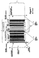
- a system may be utilized with a conveyor belt system (in which boxes having bar code labels pass by the system), or without a conveyor belt system, depending on the needs of a user of the system.
- a conveyor belt system in which boxes having bar code labels pass by the system
- a conveyor belt system in which boxes having bar code labels pass by the system
- scanners may be disposed along five separate directions -- i) in front of the conveyors, ii) behind the conveyors, iii) to one side of the conveyors, iv) to the other side of the conveyors, and v) above the conveyors.
- These systems known as five-sided scanning systems, work well to detect and decode bar code labels that may be disposed at either: i) the front of a box on the conveyor, ii) the back of the box on the conveyor, iii) one side of the box on the conveyor, iv) the other side of the box on the conveyor, or v) the top of the box on the conveyor.
- a bar code label is disposed on the bottom side of the box on the conveyor, it has to be manually repositioned by an operator prior to scanning the label, so that one of the five scanners may be able to detect the bar code label.
- the first embodiment corresponds to a six-sided scanning system.
- each pixel of a CCD-based camera is capable of receiving light from a 5-mil (0.127 mm) wide region.
- optics 860 are provided between the imaging region (that is, the top surface of the glass plate or plastic disposed in the gap 630) and the cameras, as seen in Figure 8. These optics 860 have a level of magnification sufficient to provide the desired regional coverage for the pixels of the cameras.
- the optics 860 may serve as both a magnifying and/or focusing device, as well as a cover plate for the gap region 630 (i.e., element 635 may comprise the optics).
- the top surface of the glass plate or plastic disposed in the gap 630 has a hard coating, such as a ruby coating or other type of scratch-resistant coating, so as to resist scratching from objects as they pass over the glass plate or plastic from the first conveyor 610 to the second conveyor 620.
- the optics 860 have to provide a "times 2" (x2) magnification, so as to provide a 5 mil (0.127mm) width for each pixel.
- This 5 mil width corresponds to the three pixel per minimum bar/space requirement that was set as a requirement for the system.
- six CCD cameras would be required in order to cover the entire 30-inch width of the conveyor. Similar to the optics used with the CCD cameras, additional optics may be used with the laser light source, as needed.
- a requirement of three pixels per minimum width bar/space is utilized, but one of ordinary skill in the art will recognize that any number of pixels per minimum width bar/space may be utilized while remaining within the scope of the invention, as long as at least one pixel per minimum width bar/space is met.
- having more than one pixel per minimum width bar/space is useful for properly decoding bar code labels that have print imperfections on them.
- the decoder unit 540 is only capable of receiving X-scan patterns from one or more collector units, and so the conversion modules 530A - 530C must reconfigure the two-dimensional data from each of the cameras 510A - 510C so as to provide the X-scan patterns to the decoder unit 540.
- One way of achieving this scan conversion would be to utilize a system similar to that disclosed in U.S. Patent Number 5,446,271. In the present invention, however, all of the pixel data is read into a memory within each of the conversion modules 530A - 530C, but only data from predetermined regions of the memory are outputted to the decoder module 540.
- the X-scan pattern corresponds to two 45-degree diagonal lines oppositely oriented, one diagonal line of the X-scan pattern would correspond to the first element in the first column of an n-by-n memory (that is, a memory capable of storing n 2 bits of data), the second element in the second column of the memory, ..., the n th element in the n th column of the memory.
- the other diagonal line of the X-scan pattern would correspond to the n th element of the first column, the (n-1) st element of the second column, ..., the first element of the n th column.
- a corresponding portion of the X-pattern is provided to the decoder unit 540 by each conversion module.
- a block diagram of a conversion module, such as 510A, is shown in Figure 9.
- a camera interface unit 905 is coupled to the associated camera (either 510A, 510C, or 510C).
- a direct memory access controller (DMA) 910 provides the control for sending the pixel image data from the camera interface 905 to a memory 920.
- memory 920 is a random-access-memory, and is configured as a 2048-word by 2048-word memory, which provides a symmetric block corresponding to a 10.24" square.
- the data corresponding to the two diagonal lines making up the X-scan pattern are read by a digital signal processor (DSP) 930 that is connected to the memory 920.
- DSP 930 reads the corresponding X-scan pattern data from predetermined memory locations in the memory 920 by using a program retrieved from an EEPROM 940.
- DSP 930 provides the coordination between the camera data and downloads to the decoder unit 540.
- the program stored in EEPROM 940 provides the means by which the DSP 930 retrieves the proper memory locations from the memory 920, so as to output X-scan pattern data to the decoder unit 540 (see Figure 5).
- the basic function of the system according to the first embodiment is to convert the sequential raster reads from the camera to an X pattern format familiar to the decoder unit 540.
- the array in the memory 920 will model a picture of what has passed by the camera for a finite period of time. It will also be cyclical, thereby causing the imaged barcode to traverse through the diagonal read elements in the array.
- the process involves writing into memory 920 in sequence what the camera images, and then at predefined periods reading the diagonals of the array. The whole process thus involves proper timing in reading and writing to/from memory 920.
- the writing into memory 920 (camera data) will begin at an initial point (0), and will continue until the end of the array, 2 24 - 1 words. At this point, the writing will restart at the initial point again.
- Each row is comprised of 2048 words along with a row pointer that is updated after each row is completed.
- the row pointer becomes effectively the end of the memory array.
- the row pointer also functions as an element for generating the X-pattern, since it will effectively fold the memory addressing around at the lower and upper limits.
- the reading of the diagonal elements will simulate the X pattern for an omnidirectional scanner, top left to bottom right, followed by top right to bottom left. This is achieved through subtraction and addition of one memory address to both the column and row element. For example, the first diagonal element is generated by adding 2048 + 1 to the last memory address starting at the row pointer. This is repeated 2048 times for each diagonal element. The other diagonal is generated by 2048 - 1.
- the ratio for input data rate to output date rate is 4:1. Therefore, for each four writes to the array, there will be one read to the decoder unit 540.
- the DSP 930 may be a model TMS320C3x or any other type of digital signal processor.
- Model TMS320C3x is a 32-bit processor, with the capability of addressing 16M words. Should the raw camera video be digitized for eight bits, the TMS320C3x can handle four cameras simultaneously.
- lasers are provided as the light emitting sources 520A - 520C, since a white light source (or sources) would typically not suffice for illuminating a bar code label positioned upwards with respect to a light emitting and light receiving unit.
- a laser source may be conveniently used within the small gap region between conveyors and has a better signal-to-noise ratio than a white light source (such as a lamp).
- each conversion module unit 530A - 530C converts the sequential raster read from its associated CCD camera 510A - 510C to a diagonal format familiar to the decoding unit 540.
- the decoding unit 540 is a 990 E-box manufactured by LazerData (now part of PSC Inc).
- the memory array 920 stores a snapshot of what has passed by the CCD cameras 510A - 510C for a finite period of time.
- the memory array 920 is cyclically updated.
- the imaged barcode essentially traverses through the diagonal read elements in the memory array 920.
- pixel elements from the CCD camera 510A - 510C are written into a first region (shown as a first column) of the memory 920 by the DMA 910 at a first sampling instant in time t 1 .
- each CCD element corresponds to one pixel, with one bit assigned for each pixel.
- the system according to the invention is operable with a system employing more than one pixel per CCD element and/or more than one bit assigned for each pixel.
- the memory 920 need not be reset, and so the pixel data corresponding to the (n+1)-st instant in time t n+1 is written over the data from the first instant in time t 1 , the pixel data corresponding to the (n+2)-st instant in time t n+2 is written over the data from the second instant in time t 2 , etc.
- the DSP 930 can then retrieve the data from the particular locations in the memory 920 again, in a manner similar to what it did after the n-st instant in time t n .
- Another important feature of the present invention is to have a memory system that is fast enough to provide for a particular system requirement, such as a conveyor speed.
- a system requires the reading of 15 mil (0.38mm) bar codes moving on a conveyor at 150 feet (45,7m) per minute (fpm).
- a CCD camera will be designed to have a resolution of 5 mil (0.127mm) at 200 fpm (61meter per minute)
- a 5 mil resolving capability on the CCD camera will only accurately show a minimum of 10 mil (0.25mm) bars because of the Nyquist criteria (i.e., need to sample at a rate of at least twice the highest frequency component of the input waveform).
- the CCD camera to be used in the system are designed for a maximum clock rate of 20 MHz and have a linear array of 2048 pixels.
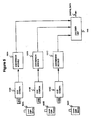
- memory 920 is depicted as a single memory in Figures 9 and 10, it may alternatively correspond to a plurality of memories 1010, 1020, 1030, as shown in Figure 11, with memory 1010 receiving pixel image data from the first camera 510A, memory 1020 receiving pixel image data from the second camera 510B, and memory 1030 receiving pixel image data from the third camera 510C (where three cameras are needed to cover an entire width of a conveyor belt, for example).
- Each memory corresponds to a particular region of a total memory 920 that corresponds to the combination of the memories 1010, 1020 and 1030, as shown in Figure 10.
- Memory 1010 would have read therein the top portions of the "X-scans", memory 1020 would have read therein the middle portions of the “X-scans”, and memory 1030 would have read therein the bottom portions of the "X-scans”.
- Each memory 1010, 1020 and 1030 has its own associated DMA and DSP, in a manner shown in Figure 11, to allow for parallel processing of the image data from the CCD cameras 510A - 510C, which is output to the decoder unit 540 in a faster manner than if only one memory was shared by the three cameras 510A - 510C.
- the number of cameras required to cover a particular image region is preferably determined based on a 5% overlap region between cameras, but any particular value can be utilized while remaining within the scope of the invention as described herein.
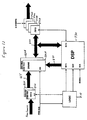
- FIG 12 is a block diagram of a raster conversion implemention that may be utilized in the first embodiment.
- DSP 930 receives a interrupt signal from logic circuit 810, where the interrupt signal is based on a frame clock signal received by logic circuit 810.
- DSP 930 also receives a high speed clock, which corresponds to a 60 MHz clock in Figure 12.
- DSP 930 outputs addresses to a first and a second dynamic RAM (DRAM) 820A, 820B on address bus 830, based on an X pattern to be read out of DRAMs 820A, 820B via data bus 840.
- DRAM dynamic RAM
- the output of CCD Camera is initially stored in an even frame FIFO 850 and an odd frame FIFO 860, based on which frame is currently being output from the camera.
- the camera data is output to DRAMs 820A, 820B via a bus 865.
- DRAM 820A receives the even frames from even frame FIFO 850
- second DRAM 820B receives the odd frames from odd frame FIFO 860.
- DRAMS 820A and 820B are written into at a rate determined by the frame clock.
- the outputs of first and second DRAMS 820A, 820B are sent to FIFOs 870A - 870D, and each FIFO is capable of supporting a separate line scanning camera.
- each FIFO is clocked at a rate of 2.048 MHz, and each FIFO provides an interrupt signal to DSP 930.
- FIFOs 870A - 870D provide an X-pattern of barcode data to decoder unit 540 (not shown in Figure 12).
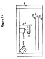
- a laser light sources 520A' and a CCD-based camera 510A' are instead positioned above a conveyor 650.
- the laser light source 520A' is positioned to output light towards a top surface of the conveyor 650.
- a height measuring unit 680 Before any object travelling on the conveyor 650 passes through a region covered by the laser light source 520A', it first passes through a height measuring unit 680, which determines a height of the object.
- the height measuring device may be constructed as a light curtain array or other type of height measuring device.
- a light curtain array that can be utilized in the system according to the second embodiment is disclosed in US-A-5699161 filed July 26, 1995, of Mark Woodworth, and assigned to PSC Inc.
- the height measuring unit 680 outputs a signal on line 513 to a processing unit 685, where the signal 513 is indicative of the height of an object passing by the height measuring unit 680. Based on the signal 513 received from the height measuring unit 680, the processing unit 685 outputs a first signal 515 to position the optics 688, and outputs a second signal 517 to position the laser light source 520A'.
- the laser light source 520A' is provided with a cylindrical lens (not shown), so as to change a "dot" of light output from the laser into a "line” of laser light.
- the laser light source 520A' is rotated to a position so as to shine light optimally onto the top surface of the object on the conveyor.
- the optics 688 provided for the CCD-based camera 510A' moves either upward or downwards, so as to properly focus the return light from a particular distance, with that particular distance corresponding to the top surface of the object passing beneath the CCD-based camera 510A'.
- both the CCD-based camera 510A' and the laser light source 520A' are positioned on a housing 681 that is in the form of a U-shape on the conveyor 650.
- Optics 688 are slidably attached to a structure 511, where optics 688 either move up or down on the structure 511 depending on the signal 515 output from the processing unit 685.
- Laser light source 520A' is rotatably positioned based on the signal 517 output from the processing unit 685.
- Other types of configurations for providing movement of optics with respect to a stationary CCD-based camera may be utilized while remaining within the scope of the invention as described herein.
- the optics 688 may be included in a lens portion of the CCD-based camera 510A', which is rotated either clockwise or counterclockwise in order to be focused to a particular distance from the CCD-based camera 510A'.
- Figure 14 shows a first line 692 corresponding to an object having a first height, and a second line 693 corresponding to an object having a second height smaller than the first height.
- the processing unit 685 outputs the first and second signals 515, 517, so as to correctly position the laser light source 520A' and the optics 688 provided between the CCD-based camera 510A' and the conveyor 650.
- the position of the laser light source 520A' and the position of the optics 688 for an object having a height corresponding to line 692 are shown by the standard lines in Figure 14. With this positioning, the system according to the example is ready to read a bar code label or other information on the top surface of the object beneath it, with that top surface corresponding to the first line 692.
- Rotational movement of the laser light source 520A' is shown by the double-sided arrow 503 in Figure 13
- linear movement of the optics 688 is shown by the double-sided arrow 506 in Figure 13.
- the system can then be repositioned for another object, such as a second object that has a second height as given by the second line 693.
- the height of the second line 693 is determined by the height measuring unit 680, and this information is sent to the processing unit 685.
- the laser light source 520A' is rotated downwardly (to a position shown by phantom lines in Figure 13) so that it shines light onto a region around the second line 693, and the optics 688 is moved upwardly (to a position shown by phantom lines in Figure 14) so as to adjust the focusing point of the light collection system to be at or around the second line 693.
- the system maintains a same resolution for objects that have differing heights, and thus are different distances away from the system.
- the system according to the example may also be utilized for other positions around the conveyor, such as to a side of a conveyor. In that case, the distance that the object is with respect to the side of the conveyor can be determined prior to the object passing by the scanning system, such as in a manner disclosed in US-A-5 699 161.
- the system according to the example provides an autofocusing for obj ects as they pass by, based on rotational movement of laser light sources and linear movement of optics provided for CCD-based cameras. Another type of autofocusing system is described in U.S.
- Patent 5,317,166 issued to Benny Tafoya, and assigned to PSC Inc., which is incorporated in its entirety herein by reference.
- CCD-based cameras such as in the present invention.
- the system may also be configured with a plurality of laser light sources and CCD-based cameras, with each pair covering a particular widthwise area on the conveyor. With this configuration, labels on the top as well as the sides of an object passing below the laser light sources and CCD-based cameras may be read and decoded.
- CCD camera 1110 is capable of outputting a matrix array of data at periodic instants in time, and thus corresponds to a two-dimensional CCD camera.
- the array may be an n x n array, or an m x n array of pixel elements, where m and n are integers.
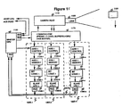
- Common logic unit 1170 provides the logic for temporarily storing data from the CCD camera head 1110, and may be configured as a plurality of buffers 1400-1 to 1400-n that are clocked by a clock signal 1420 to receive data from the CCD camera head 1110, as in Figure 16.
- common logic unit 1170 includes a 1028-bit x 1028-bit memory array, which stores pixel data from the CCD camera 1110 at periodic time instants.
- the memory array may be configured as a plurality of buffers, as shown in Figure 16, or it may be configured as a random access memory that is updated at periodic instants in time, or by any other temporary storage device, as is known to one of ordinary skill in the art.
- a master CPU 1130 initializes each of the axis controllers 1120-1 to 1120-n, so that each axis controller extracts "pertinent data" of the pixel data read by the CCD cameras on each scan, and stores the pertinent data into a proper location in a corresponding axis memory 1150-1 to 1150-n.
- each axis 1255-1 to 1255-n has an associated axis controller, an associated axis memory, an associated bit logic unit, and an associated slave processor.
- Each axis 1255-1 to 1255-n may be configured as a separate axis card, as shown by the dashed lines in Figure 15.
- the repeat count for each axis controller is initialized by the master CPU 1130.
- scan lines such as horizontal scan lines
- some of the axis controllers 1120-1 - 1120-n have a counter that causes sequential writes to occur following a trigger. This function is initialized prior to a scan.
- each axis has its associated scan counter initialized.
- the first trigger point a given axis find on any given line may not be the zeroth scan for that axis.
- the first data point on the first scan will be used by the 45 degree axis controller, but may not necessarily be the first 45 degree scan. It may, however, become the center scan when the generation is complete. For this reason, the number of the first scan must be loaded prior to initiation of the scanning operation.
- a 1028 by 1028 array of pixel data is received from the read head of the CCD camera 1110.
- a position clock is returned as well. This position clock is used to advance the counter of each of the axis controllers. The position clock is used to determine which scan the data currently stored in the common logic unit 1170 corresponds to.
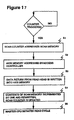
- a counter for any of the axis controllers 1120-1 - 1120-n When a counter for any of the axis controllers 1120-1 - 1120-n is triggered, the following steps occur, as shown in Figure 17.
- the counter for each axis controller sequentially addresses the temporarily-stored data in the common logic unit 1170 via the select line 1410, as shown in Figure 16.
- a counter for reading data into the corresponding axis memory is initialized to zero on a read operation that follows the scan.
- an axis memory 1150-1 - 1150-n associated with the axis controller is addressed by the axis controller to determine which scan is being written, and to determine where in the scan the bit belongs.
- a third step S3 data from predetermined memory locations (or buffers) returned from the read head of the CCD camera 1110 are now written sequentially into the axis memory.
- a fourth step S4 the contents of the common logic unit 1170 are incremented by one and rewritten. If an axis controller is not required to write multiple sequential locations from a same scan line, the scan-counter associated with the axis controller is incremented. It now addresses the next location in the scan memory, and is ready for the next trigger. In the event that a multiple write is required, the write is repeated each clock period until the required number of writes takes place. The scan counter is then updated.
- a fifth step S5 the master CPU 1130 initiates a read cycle.
- no memory refresh cycle is required, as the data is read only once, and this will take place within the maximum refresh period for the memory.
- a bit logic unit 1180-1 to 1180-n for each axis will rapidly read all sequential memory locations within it associated the axis memory. As each location is read, a count is generated of the time since the last data transition. Each time a data transition is detected, the count since the last transition is passed to an associated slave processor 1160-1 to 1160-n.
- Each slave processor 1160-1 to 1160-n utilizes the information retrieved from its corresponding bit logic unit 1180-1 to 1180-n in order to determine if a potentially valid bar code may have been read. This determination is based on known characteristics of bar code labels, such as quiet zone size, minimum width and maximum width bar code sizes, etc. If the information retrieved from the corresponding bit logic unit is such that the data cannot correspond to a true bar code, then that data is not sent to the master CPU 1130 for decoding. If, however, the data can possibly be a true bar code, then that data is sent to the master CPU 1130 for decoding.
- Each slave processor 1160-1 - 1160-n is polled by the master CPU 1130 in a periodic manner, and if a potential bar code has been located, it will be passed to the master CPU 1130 for decoding.
- Each slave processor is connected to its corresponding bit logic unit 1180-1 - 1180-n, which is itself connected to its corresponding axis memory 1150-1 - 1150-n.
- each bit logic unit 1180-1 - 1180-n corresponds to a first-in, first-out buffer (FIFO), where bar widths and bar spaces are stored as 8-bit wide elements in the 9-bit x 256-bit FIFO. That is, consecutive ones correspond to a particular bar width, and consecutive zeros correspond to a particular space width.
- FIFO first-in, first-out buffer
- the ninth bit for each storage location in the bit logic unit corresponds to a quiet-zone bit.
- the quiet-zone bit indicates whether or not a quiet-zone has been scanned.
- Other configurations of the bit logic unit may be envisioned by one of ordinary skill in the art, while remaining within the scope of the invention as described herein.
- the master CPU 1130 will place all axis controllers in a "horizontal" mode, and may initiate practice scans with artificial data, if desired.
- the slave processors 1160-1 to 1160-n will verify that all of the data is correct, and report this to the master CPU 1130. Both the slave processors 1160-1 to 1160-n and the master CPU 1130 may run internal diagnostics when not actively scanning the read data.
- both the slave processors 1160-1 to 1160-n and the master CPU 1130 have a corresponding parallel input/output (PIO) port, for transmitting and receiving data between the master CPU and the slave processor.
- the master CPU 1130 sends control signals to the common logic unit 1170 via another PIO port, and communicates with a host CPU (not shown) and an auxiliary port (not shown) via a serial input/output (SIO) port.
- PIO parallel input/output
- each buffer of the common logic unit 1170 is sampled based on a select signal and a clock signal. For example, for a 45 degree scan line, the leftmost buffer 1400-1 on the top row is sampled at a time to and output to the axis controller for the 45 degree axis, the next-to-leftmost buffer 1400-(m+2) on the second row is sampled at a time t m+2 and output to the axis controller for the 45 degree axis, and so on.
- the sampling of each of the buffers is performed at a fast enough rate so that all of the buffers are sampled prior to a next scan (and therefore reloading) of data into the common logic unit 1170.
Claims (7)
- Strichcode Lesesystem, umfassend:ein erstes Förderband (610), um Gegenstände von einem ersten Ort zu einem zweiten Ort zu befördern;ein zweites Förderband (620) zur Aufnahme von Objekten von dem ersten Förderband und zur Bewegung der Objekte zu einem dritten Ort;einen Lichtsender (520A-520C), der in einer Lücke (630) unterhalb einer Oberseite des ersten und zweiten Förderbandes (610 und 620) platziert ist, der zum Beleuchten der Strichcode Etiketten auf der Unterseite der Objekte konfiguriert ist, wenn die Objekte von dem ersten Förderband (610) zu dem zweiten Förderband (620) bewegt werden;einen Lichtempfänger (510A-510C), der in der Lücke (630) platziert ist und der zum Empfangen von reflektiertem Licht von der Unterseite der Objekte aufgrund der durch den Lichtsender (520A-520C) beleuchteten Objekte konfiguriert ist; undeine fensterartige Einheit (635) vollständig innerhalb der Lücke (630) angeordnet ist, wobei die Oberseite der fensterartigen Einheit (635) eine im Wesentlichen mit den Oberseiten des ersten und zweiten Förderbandes (610 und 620) kontinuierliche Oberseite bereitstellt , wenn die Objekte von dem ersten Ort zu dem dritten Ort bewegt werden,dadurch gekennzeichnet, dass die fensterartige Einheit (635) eine Oberseite aufweist, die entlang einer selben Ebene wie die Oberseiten des ersten und zweiten Förderbandes (610 und 620) gelegen ist und
dass die fensterartige Einheit (635) eine Vergrößerung für das Ausgangslicht des Lichtsenders (520A- 520C) bereitstellt und die Vergrößerung eine Kompensation in der Art bereitstellt, dass der Lichtempfänger (510A-510C) Licht empfangen kann von mehreren Bereichen der Oberseite der fensterartigen Einheit (635) als ohne die Vergrößerung. - Strichcode Lesesystem nach Anspruch 1, wobei der Lichtempfänger (510A-510C) wenigstens eine CCD Kamera (510-510C) aufweist, die eine Vielzahl von Pixelelementen hat und jedes Pixelelement Licht von einem bestimmten Bereich der Oberseite der fensterartigen Einheit (635) empfängt.
- Strichcode Lesesystem nach einem der vorhergehenden Ansprüche, wobei die fensterartige Einheit (635) Glas oder Kunststoff umfasst.
- Strichcode Lesesystem nach einem der vorhergehenden Ansprüche, wobei eine Breite der Oberseite der fensterartigen Einheit (635) eine derartige Größe hat, dass wenigstens die eine Kamera selbst nicht in der Lage ist, direkt Licht von allen Bereichen der Oberseite der fensterähnlichen Einheit (635) zu empfangen, und wobei die Vergrößerung eine Kompensation in der Art bereitstellt, dass wenigstens die eine CCD Kamera in der Lage ist, Licht zu empfangen von allen Bereichen der Oberseite der fensterartigen Einheit (635).
- Strichcode Lesesystem nach einem der vorhergehenden Ansprüche, weiter umfassend:ein erstes Lichtsendereinheits- und Lichtempfängereinheitspaar, angeordnet zum Detektieren eines Strichcode Etiketts an einer Vorderseite des Objekts bei einer Objektbewegung entlang eines ersten und zweiten Förderbandes, die Frontseite ist bezüglich einer Bewegungsrichtung der Objekte ausgerichtet;ein zweites Lichtsendereinheits- und Lichtempfängereinheitspaar, angeordnet zum Detektieren eines Strichcode Etiketts an einer Rückseite des Objekts bei einer Objektbewegung entlang des ersten und zweiten Förderbandes, die Rückseite ist bezüglich einer Bewegungsrichtung der Objekte ausgerichtet;ein drittes Lichtsendereinheits- und Lichtempfängereinheitspaar, angeordnet zum Erkennen eines Strichcode Etiketts an einer Seite des Objekts während der Objektbewegung entlang des ersten und zweiten Förderbands, die eine Seite ist im Wesentlichen senkrecht bezüglich der Oberseite des ersten und zweiten Förderbandes ausgerichtet;ein viertes Lichtsendereinheits- und Lichtempfängereinheitspaar, angeordnet zum Erkennen eines Strichcode Etiketts auf einer anderen Seite des Objektes während der Objektbewegung entlang des ersten und zweiten Förderbands, die andere Seite ist im Wesentlichen senkrecht bezüglich der Oberseite des ersten und zweiten Förderbands ausgerichtet;ein fünftes Lichtsendereinheits- und Lichtempfängereinheitspaar, angeordnet zum Erkennen eines Strichcode Etiketts auf einer Oberseite des Objekts entlang der Objektbewegung des ersten und zweiten Förderbandes, wobei die Lichtsendeeinheit und Lichtempfangseinheit zusammen ein sechstes Lichtsendeeinheits- und Lichtempfangseinheitspaar bilden.
- Strichcode Lesesystem nach Anspruch 5, wobei das Strichcode Lesesystem geeignet ist zum Erkennen eines irgendwo am Objekt angeordneten Strichcode Etiketts während der Objektbewegung von dem ersten Ort zu dem dritten Ort.
- Strichcode Lesesystem nach einem der vorhergehenden Ansprüche, wobei eines der ersten und zweiten Förderbänder (610 und 620) einem Mitnahmeförderband entspricht und das andere von dem ersten und zweiten Förderband (610 und 620) einem Zuführungsförderband entspricht.
Applications Claiming Priority (3)
| Application Number | Priority Date | Filing Date | Title |
|---|---|---|---|
| US959680 | 1997-10-29 | ||
| US08/959,680 US5984186A (en) | 1997-10-29 | 1997-10-29 | CCD-base bar code scanner |
| PCT/US1998/022638 WO1999022335A1 (en) | 1997-10-29 | 1998-10-29 | Ccd-based bar code scanner |
Publications (3)
| Publication Number | Publication Date |
|---|---|
| EP1025532A1 EP1025532A1 (de) | 2000-08-09 |
| EP1025532A4 EP1025532A4 (de) | 2002-07-31 |
| EP1025532B1 true EP1025532B1 (de) | 2006-03-29 |
Family
ID=25502283
Family Applications (1)
| Application Number | Title | Priority Date | Filing Date |
|---|---|---|---|
| EP98956199A Expired - Lifetime EP1025532B1 (de) | 1997-10-29 | 1998-10-29 | Ccd-basierter bar-kode-scanner |
Country Status (4)
| Country | Link |
|---|---|
| US (2) | US5984186A (de) |
| EP (1) | EP1025532B1 (de) |
| DE (1) | DE69834053T2 (de) |
| WO (1) | WO1999022335A1 (de) |
Cited By (1)
| Publication number | Priority date | Publication date | Assignee | Title |
|---|---|---|---|---|
| CN103837539A (zh) * | 2012-11-22 | 2014-06-04 | 景硕科技股份有限公司 | 终端检验系统 |
Families Citing this family (57)
| Publication number | Priority date | Publication date | Assignee | Title |
|---|---|---|---|---|
| US6631842B1 (en) | 2000-06-07 | 2003-10-14 | Metrologic Instruments, Inc. | Method of and system for producing images of objects using planar laser illumination beams and image detection arrays |
| US7387253B1 (en) | 1996-09-03 | 2008-06-17 | Hand Held Products, Inc. | Optical reader system comprising local host processor and optical reader |
| US6385645B1 (en) * | 1995-08-04 | 2002-05-07 | Belle Gate Investments B.V. | Data exchange system comprising portable data processing units |
| US6619550B1 (en) | 1995-12-18 | 2003-09-16 | Metrologic Instruments, Inc. | Automated tunnel-type laser scanning system employing corner-projected orthogonal laser scanning patterns for enhanced reading of ladder and picket fence oriented bar codes on packages moving therethrough |
| US6360947B1 (en) | 1995-12-18 | 2002-03-26 | Metrologic Instruments, Inc. | Automated holographic-based tunnel-type laser scanning system for omni-directional scanning of bar code symbols on package surfaces facing any direction or orientation within a three-dimensional scanning volume disposed above a conveyor belt |
| US20020014533A1 (en) * | 1995-12-18 | 2002-02-07 | Xiaxun Zhu | Automated object dimensioning system employing contour tracing, vertice detection, and forner point detection and reduction methods on 2-d range data maps |
| US6554189B1 (en) | 1996-10-07 | 2003-04-29 | Metrologic Instruments, Inc. | Automated system and method for identifying and measuring packages transported through a laser scanning tunnel |
| US6382515B1 (en) | 1995-12-18 | 2002-05-07 | Metrologic Instruments, Inc. | Automated system and method for identifying and measuring packages transported through a laser scanning tunnel |
| US6517004B2 (en) | 1995-12-18 | 2003-02-11 | Metrologic Instruments, Inc. | Automated system for identifying and dimensioning packages transported through a laser scanning tunnel using laser scanning beam indexing techniques |
| US6457642B1 (en) | 1995-12-18 | 2002-10-01 | Metrologic Instruments, Inc. | Automated system and method for identifying and measuring packages transported through a laser scanning tunnel |
| US7028899B2 (en) | 1999-06-07 | 2006-04-18 | Metrologic Instruments, Inc. | Method of speckle-noise pattern reduction and apparatus therefore based on reducing the temporal-coherence of the planar laser illumination beam before it illuminates the target object by applying temporal phase modulation techniques during the transmission of the plib towards the target |
| US7673803B2 (en) | 1998-03-24 | 2010-03-09 | Metrologic Instruments, Inc. | Planar laser illumination and imaging (PLIIM) based engine |
| US6996213B1 (en) * | 1998-09-29 | 2006-02-07 | Sun Microsystems, Inc. | Superposition of data over voice |
| WO2000077640A1 (en) | 1999-06-10 | 2000-12-21 | Belle Gate Investment B.V. | Arrangements storing different versions of a set of data in separate memory areas and method for updating a set of data in a memory |
| US6431450B1 (en) * | 1999-09-13 | 2002-08-13 | Advanced Technology & Research Corp. | Barcode scanning system for reading labels at the bottom of packages on a conveyor |
| US6296187B1 (en) * | 1999-11-12 | 2001-10-02 | Psc Inc. | CCD-based bar code scanner |
| WO2001040910A1 (en) * | 1999-12-06 | 2001-06-07 | De Jong, Eduard, Karel | Computer arrangement using non-refreshed dram |
| BR9917573A (pt) * | 1999-12-07 | 2002-08-06 | Sun Microsystems Inc | Dispositiivo de identiificação que contém uma foto segura, assim como um meio e método para autenticação de tal dispositiivo de identificação |
| ATE378679T1 (de) | 1999-12-07 | 2007-11-15 | Sun Microsystems Inc | Computerlesbares medium mit mikroprozessor zur lesesteuerung und computeranordnung zur kommunikation mit einem derartigen medium |
| US6726094B1 (en) * | 2000-01-19 | 2004-04-27 | Ncr Corporation | Method and apparatus for multiple format image capture for use in retail transactions |
| US7100832B2 (en) * | 2000-04-18 | 2006-09-05 | Metrologic Instruments, Inc. | Bioptical laser scanning system providing 360° of omnidirectional bar code symbol scanning coverage at point of sale station |
| CA2416844A1 (en) | 2000-07-20 | 2002-01-31 | Belle Gate Investment B.V. | Method and system of communicating devices, and devices therefor, with protected data transfer |
| US6739513B1 (en) * | 2000-09-05 | 2004-05-25 | Rjs Systems International | Box detector in barcode environment |
| US7954719B2 (en) | 2000-11-24 | 2011-06-07 | Metrologic Instruments, Inc. | Tunnel-type digital imaging-based self-checkout system for use in retail point-of-sale environments |
| US6749120B2 (en) * | 2000-12-11 | 2004-06-15 | Cpo Technologies Corp. | Method and apparatus for scanning electronic barcodes |
| US7268924B2 (en) | 2001-01-22 | 2007-09-11 | Hand Held Products, Inc. | Optical reader having reduced parameter determination delay |
| ATE335246T1 (de) * | 2001-01-22 | 2006-08-15 | Hand Held Prod Inc | Optischer leser mit teilbild-ausschnitt-funktion |
| US6637658B2 (en) | 2001-01-22 | 2003-10-28 | Welch Allyn, Inc. | Optical reader having partial frame operating mode |
| US7331523B2 (en) | 2001-07-13 | 2008-02-19 | Hand Held Products, Inc. | Adaptive optical image reader |
| US8239271B2 (en) * | 2001-09-04 | 2012-08-07 | Ncr Corporation | Methods and apparatus for managing sequencing of data received from devices in a retail point of sale system |
| SE520682C2 (sv) * | 2001-12-06 | 2003-08-12 | Anoto Ab | Rekonstruering av ett virtuellt raster |
| US6637893B2 (en) | 2002-03-22 | 2003-10-28 | Accu-Sort Systems, Inc. | Presentation imaging system |
| US6805449B2 (en) * | 2002-03-22 | 2004-10-19 | Accu-Sort Systems, Inc. | Presentation imaging system |
| TWM306698U (en) * | 2006-03-01 | 2007-02-21 | Riotec Co Ltd | Optical structure improvement of bar code reader |
| US7852519B2 (en) | 2007-02-05 | 2010-12-14 | Hand Held Products, Inc. | Dual-tasking decoder for improved symbol reading |
| US7726575B2 (en) * | 2007-08-10 | 2010-06-01 | Hand Held Products, Inc. | Indicia reading terminal having spatial measurement functionality |
| US9412124B2 (en) * | 2007-09-23 | 2016-08-09 | Sunrise R&D Holdings, Llc | Multi-item scanning systems and methods of items for purchase in a retail environment |
| WO2009102616A2 (en) | 2008-02-12 | 2009-08-20 | Datalogic Scanning, Inc. | Systems and methods for forming a composite image of multiple portions of an object from multiple perspectives |
| US8678287B2 (en) | 2008-02-12 | 2014-03-25 | Datalogic ADC, Inc. | Two-plane optical code reader for acquisition of multiple views of an object |
| US8608076B2 (en) * | 2008-02-12 | 2013-12-17 | Datalogic ADC, Inc. | Monolithic mirror structure for use in a multi-perspective optical code reader |
| US8353457B2 (en) * | 2008-02-12 | 2013-01-15 | Datalogic ADC, Inc. | Systems and methods for forming a composite image of multiple portions of an object from multiple perspectives |
| US8628015B2 (en) | 2008-10-31 | 2014-01-14 | Hand Held Products, Inc. | Indicia reading terminal including frame quality evaluation processing |
| US8261990B2 (en) * | 2008-12-26 | 2012-09-11 | Datalogic ADC, Inc. | Data reader having compact arrangement for acquisition of multiple views of an object |
| US8322621B2 (en) | 2008-12-26 | 2012-12-04 | Datalogic ADC, Inc. | Image-based code reader for acquisition of multiple views of an object and methods for employing same |
| US8643717B2 (en) * | 2009-03-04 | 2014-02-04 | Hand Held Products, Inc. | System and method for measuring irregular objects with a single camera |
| DE102009037124A1 (de) * | 2009-08-11 | 2011-02-17 | Wincor Nixdorf International Gmbh | Vorrichtung und Verfahren zum optischen Abtasten einer maschinenlesbaren Markierung |
| US8587595B2 (en) | 2009-10-01 | 2013-11-19 | Hand Held Products, Inc. | Low power multi-core decoder system and method |
| WO2012103067A2 (en) | 2011-01-24 | 2012-08-02 | Datalogic ADC, Inc. | Modular scanner component mounting system for checkstand |
| US20120187195A1 (en) * | 2011-01-24 | 2012-07-26 | Datalogic ADC, Inc. | Systems and methods for reading encoded data through gaps between conveyors in an automated checkout system |
| US8523076B2 (en) | 2012-01-10 | 2013-09-03 | Metrologic Instruments, Inc. | Omnidirectional laser scanning bar code symbol reader generating a laser scanning pattern with a highly non-uniform scan density with respect to line orientation |
| US9552507B2 (en) * | 2012-05-07 | 2017-01-24 | Datalogic Usa, Inc. | System and method for reading optical codes on bottom surface of items |
| US8997972B2 (en) | 2012-07-27 | 2015-04-07 | Datalogic ADC, Inc. | Systems and methods for transferring items over transition gap between conveyor sections of automated checkout system |
| US10154177B2 (en) * | 2012-10-04 | 2018-12-11 | Cognex Corporation | Symbology reader with multi-core processor |
| CN103839119B (zh) * | 2012-11-22 | 2016-12-21 | 景硕科技股份有限公司 | 终端缺陷检验的方法 |
| US8783438B2 (en) | 2012-11-30 | 2014-07-22 | Heb Grocery Company, L.P. | Diverter arm for retail checkstand and retail checkstands and methods incorporating same |
| CN108906660B (zh) * | 2018-06-27 | 2021-03-16 | 大族激光科技产业集团股份有限公司 | 一种激光打标产品的自动检测分拣装置 |
| CN111871832A (zh) * | 2020-07-14 | 2020-11-03 | 深圳路辉物流设备有限公司 | 用于分拣流水线的包裹分拣装置、方法及存储介质 |
Family Cites Families (29)
| Publication number | Priority date | Publication date | Assignee | Title |
|---|---|---|---|---|
| US3774014A (en) * | 1972-03-20 | 1973-11-20 | Pitney Bowes Alpex | Printed code scanning system |
| US4282425A (en) * | 1979-07-25 | 1981-08-04 | Norand Corporation | Instant portable bar code reader |
| DE3043985A1 (de) * | 1980-11-21 | 1982-06-03 | Hermann 7742 St Georgen Stockburger | Verfahren und vorrichtung zur kennzeichnung und/oder identifizierung eines datentraegers |
| US4457585A (en) * | 1981-08-31 | 1984-07-03 | Ducorday Gerard M | Magnifier reader |
| US4877949A (en) * | 1986-08-08 | 1989-10-31 | Norand Corporation | Hand-held instant bar code reader system with automated focus based on distance measurements |
| US5308966A (en) * | 1986-08-08 | 1994-05-03 | Norand Corporation | Hand-held instant bar code reader having automatic focus control for operation over a range of distances |
| US4939355A (en) * | 1988-01-22 | 1990-07-03 | Spectra-Physics, Inc. | Automatic package label scanner |
| US5569901A (en) * | 1988-10-21 | 1996-10-29 | Symbol Technologies, Inc. | Symbol scanning system and method having adaptive pattern generation |
| US5019714A (en) * | 1989-02-06 | 1991-05-28 | Metrologic Instruments, Inc. | Scanning system with array of laser scanner modules to produce complex scan pattern |
| CA1334218C (en) * | 1989-03-01 | 1995-01-31 | Jerome Swartz | Hand-held laser scanning for reading two dimensional bar codes |
| CA1329263C (en) * | 1989-03-01 | 1994-05-03 | Mark Krichever | Bar code scanner |
| US5319181A (en) * | 1992-03-16 | 1994-06-07 | Symbol Technologies, Inc. | Method and apparatus for decoding two-dimensional bar code using CCD/CMD camera |
| US5495097A (en) * | 1993-09-14 | 1996-02-27 | Symbol Technologies, Inc. | Plurality of scan units with scan stitching |
| US5256864A (en) * | 1991-09-24 | 1993-10-26 | Spectra-Physics | Scanning system for preferentially aligning a package in an optimal scanning plane for decoding a bar code label |
| US5298728A (en) * | 1991-11-01 | 1994-03-29 | Spectra-Physics Scanning System, Inc. | Signal processing apparatus and method |
| JP2727037B2 (ja) * | 1992-04-20 | 1998-03-11 | 富士通株式会社 | バーコード読取り装置 |
| JP3154809B2 (ja) * | 1992-05-26 | 2001-04-09 | オリンパス光学工業株式会社 | バーコードリーダ装置 |
| US5252814A (en) * | 1992-08-17 | 1993-10-12 | Ncr Corporation | Multi-scanner checkout counter using digitizer panel to determine X-Y location of scanned items |
| US5268580A (en) * | 1992-09-02 | 1993-12-07 | Ncr Corporation | Bar code enhancement system and method for vision scanners |
| US5296691A (en) * | 1992-09-14 | 1994-03-22 | Lazerdata Corporation | Scanning device for reconstructing a complete code from scanned segments |
| US5481097A (en) * | 1993-01-25 | 1996-01-02 | Psc Inc. | Apparatus and method for decoding bar codes |
| US5399852A (en) * | 1993-02-19 | 1995-03-21 | United Parcel Service Of America, Inc. | Method and apparatus for illumination and imaging of a surface employing cross polarization |
| US5317166A (en) * | 1993-02-23 | 1994-05-31 | Psc Inc. | A system for decoding bar coded labels upon different size containers |
| US5382783A (en) * | 1993-05-10 | 1995-01-17 | Psc Inc. | False bar code inhibitor circuit |
| US5446271A (en) * | 1993-08-06 | 1995-08-29 | Spectra-Physics Scanning Systems, Inc. | Omnidirectional scanning method and apparatus |
| US5463214A (en) * | 1994-03-04 | 1995-10-31 | Welch Allyn, Inc. | Apparatus for optimizing throughput in decoded-output scanners and method of using same |
| US5521366A (en) * | 1994-07-26 | 1996-05-28 | Metanetics Corporation | Dataform readers having controlled and overlapped exposure integration periods |
| US5600121A (en) * | 1995-03-20 | 1997-02-04 | Symbol Technologies, Inc. | Optical reader with independent triggering and graphical user interface |
| US5585616A (en) * | 1995-05-05 | 1996-12-17 | Rockwell International Corporation | Camera for capturing and decoding machine-readable matrix symbol images applied to reflective surfaces |
-
1997
- 1997-10-29 US US08/959,680 patent/US5984186A/en not_active Expired - Lifetime
-
1998
- 1998-10-29 DE DE69834053T patent/DE69834053T2/de not_active Expired - Lifetime
- 1998-10-29 WO PCT/US1998/022638 patent/WO1999022335A1/en active IP Right Grant
- 1998-10-29 EP EP98956199A patent/EP1025532B1/de not_active Expired - Lifetime
-
1999
- 1999-11-09 US US09/436,630 patent/US6257490B1/en not_active Expired - Lifetime
Cited By (2)
| Publication number | Priority date | Publication date | Assignee | Title |
|---|---|---|---|---|
| CN103837539A (zh) * | 2012-11-22 | 2014-06-04 | 景硕科技股份有限公司 | 终端检验系统 |
| CN103837539B (zh) * | 2012-11-22 | 2016-08-03 | 景硕科技股份有限公司 | 终端检验系统 |
Also Published As
| Publication number | Publication date |
|---|---|
| DE69834053D1 (de) | 2006-05-18 |
| EP1025532A4 (de) | 2002-07-31 |
| WO1999022335A1 (en) | 1999-05-06 |
| DE69834053T2 (de) | 2007-05-10 |
| EP1025532A1 (de) | 2000-08-09 |
| WO1999022335A9 (en) | 1999-07-01 |
| US6257490B1 (en) | 2001-07-10 |
| US5984186A (en) | 1999-11-16 |
Similar Documents
| Publication | Publication Date | Title |
|---|---|---|
| EP1025532B1 (de) | Ccd-basierter bar-kode-scanner | |
| US6296187B1 (en) | CCD-based bar code scanner | |
| US6142376A (en) | Method and apparatus for reading symbols on items moved by conveyor | |
| EP0980537B1 (de) | Optische abtastvorrichtung und bildleser zum bildlesen und dekodieren optischer information mit eine-und zweidimensionalen symbolen bei veränderlicher tiefenschärfe | |
| EP0385478B1 (de) | Strichkodeleser | |
| US5414250A (en) | Method and apparatus for reading two-dimensional bar code employing bit-mapped imaging | |
| US4500776A (en) | Method and apparatus for remotely reading and decoding bar codes | |
| US6783068B2 (en) | Large depth of field line scan camera | |
| JP3230612B2 (ja) | 2次元バーコードリーダ | |
| US7322526B1 (en) | System for reading optical indicia | |
| US5136145A (en) | Symbol reader | |
| US20060278712A1 (en) | Method and system for data reading using raster scanning | |
| US5959286A (en) | Method and apparatus for raster scanning of images | |
| US5991470A (en) | One-dimensional scanner system for two-dimensional image acquisition | |
| US6523753B2 (en) | System for reading barcode symbols | |
| US6307208B1 (en) | System for reading barcode symbols | |
| EP1916557B1 (de) | Optischer Scanner und Bildlesegerät zum Lesen von Bildern und Dekodieren optischer Informationen einschließlich ein- und zweidimensionaler Symbologien mit variabler Feldtiefe | |
| JPH0954810A (ja) | データシンボル読み取り装置 | |
| EP1178665A2 (de) | Optischer Scanner und Bildleser mit ein- und zweidimensionalen Symbologien bei variabler Feldtiefe | |
| CA2577235A1 (en) | Optical scanner and image reader for reading images and decoding optical information including one and two dimensional symbologies at variable depth of field | |
| JPH0690739B2 (ja) | 光学式文字読取装置 |
Legal Events
| Date | Code | Title | Description |
|---|---|---|---|
| PUAI | Public reference made under article 153(3) epc to a published international application that has entered the european phase |
Free format text: ORIGINAL CODE: 0009012 |
|
| 17P | Request for examination filed |
Effective date: 20000428 |
|
| AK | Designated contracting states |
Kind code of ref document: A1 Designated state(s): DE FR GB IT |
|
| RAP1 | Party data changed (applicant data changed or rights of an application transferred) |
Owner name: SICK, INC. |
|
| A4 | Supplementary search report drawn up and despatched |
Effective date: 20020619 |
|
| AK | Designated contracting states |
Kind code of ref document: A4 Designated state(s): DE FR GB IT |
|
| RIC1 | Information provided on ipc code assigned before grant |
Free format text: 7G 06K 7/10 A, 7B 07C 5/34 B |
|
| 17Q | First examination report despatched |
Effective date: 20040924 |
|
| RAP1 | Party data changed (applicant data changed or rights of an application transferred) |
Owner name: SICK, INC. |
|
| GRAP | Despatch of communication of intention to grant a patent |
Free format text: ORIGINAL CODE: EPIDOSNIGR1 |
|
| GRAS | Grant fee paid |
Free format text: ORIGINAL CODE: EPIDOSNIGR3 |
|
| GRAA | (expected) grant |
Free format text: ORIGINAL CODE: 0009210 |
|
| AK | Designated contracting states |
Kind code of ref document: B1 Designated state(s): DE FR GB IT |
|
| PG25 | Lapsed in a contracting state [announced via postgrant information from national office to epo] |
Ref country code: IT Free format text: LAPSE BECAUSE OF FAILURE TO SUBMIT A TRANSLATION OF THE DESCRIPTION OR TO PAY THE FEE WITHIN THE PRESCRIBED TIME-LIMIT;WARNING: LAPSES OF ITALIAN PATENTS WITH EFFECTIVE DATE BEFORE 2007 MAY HAVE OCCURRED AT ANY TIME BEFORE 2007. THE CORRECT EFFECTIVE DATE MAY BE DIFFERENT FROM THE ONE RECORDED. Effective date: 20060329 |
|
| REG | Reference to a national code |
Ref country code: GB Ref legal event code: FG4D |
|
| REF | Corresponds to: |
Ref document number: 69834053 Country of ref document: DE Date of ref document: 20060518 Kind code of ref document: P |
|
| ET | Fr: translation filed | ||
| PLBE | No opposition filed within time limit |
Free format text: ORIGINAL CODE: 0009261 |
|
| STAA | Information on the status of an ep patent application or granted ep patent |
Free format text: STATUS: NO OPPOSITION FILED WITHIN TIME LIMIT |
|
| 26N | No opposition filed |
Effective date: 20070102 |
|
| PGFP | Annual fee paid to national office [announced via postgrant information from national office to epo] |
Ref country code: FR Payment date: 20141021 Year of fee payment: 17 Ref country code: DE Payment date: 20141024 Year of fee payment: 17 Ref country code: GB Payment date: 20141024 Year of fee payment: 17 |
|
| PGFP | Annual fee paid to national office [announced via postgrant information from national office to epo] |
Ref country code: IT Payment date: 20141027 Year of fee payment: 17 |
|
| REG | Reference to a national code |
Ref country code: DE Ref legal event code: R119 Ref document number: 69834053 Country of ref document: DE |
|
| GBPC | Gb: european patent ceased through non-payment of renewal fee |
Effective date: 20151029 |
|
| PG25 | Lapsed in a contracting state [announced via postgrant information from national office to epo] |
Ref country code: DE Free format text: LAPSE BECAUSE OF NON-PAYMENT OF DUE FEES Effective date: 20160503 Ref country code: GB Free format text: LAPSE BECAUSE OF NON-PAYMENT OF DUE FEES Effective date: 20151029 Ref country code: IT Free format text: LAPSE BECAUSE OF NON-PAYMENT OF DUE FEES Effective date: 20151029 |
|
| REG | Reference to a national code |
Ref country code: FR Ref legal event code: ST Effective date: 20160630 |
|
| PG25 | Lapsed in a contracting state [announced via postgrant information from national office to epo] |
Ref country code: FR Free format text: LAPSE BECAUSE OF NON-PAYMENT OF DUE FEES Effective date: 20151102 |