EP1024922B1 - Method and apparatus for assembling exhaust components - Google Patents
Method and apparatus for assembling exhaust components Download PDFInfo
- Publication number
- EP1024922B1 EP1024922B1 EP98950970A EP98950970A EP1024922B1 EP 1024922 B1 EP1024922 B1 EP 1024922B1 EP 98950970 A EP98950970 A EP 98950970A EP 98950970 A EP98950970 A EP 98950970A EP 1024922 B1 EP1024922 B1 EP 1024922B1
- Authority
- EP
- European Patent Office
- Prior art keywords
- end cap
- jaws
- crimpable
- exhaust processor
- sizer
- Prior art date
- Legal status (The legal status is an assumption and is not a legal conclusion. Google has not performed a legal analysis and makes no representation as to the accuracy of the status listed.)
- Expired - Lifetime
Links
Images




Classifications
-
- F—MECHANICAL ENGINEERING; LIGHTING; HEATING; WEAPONS; BLASTING
- F01—MACHINES OR ENGINES IN GENERAL; ENGINE PLANTS IN GENERAL; STEAM ENGINES
- F01N—GAS-FLOW SILENCERS OR EXHAUST APPARATUS FOR MACHINES OR ENGINES IN GENERAL; GAS-FLOW SILENCERS OR EXHAUST APPARATUS FOR INTERNAL-COMBUSTION ENGINES
- F01N13/00—Exhaust or silencing apparatus characterised by constructional features
- F01N13/18—Construction facilitating manufacture, assembly, or disassembly
- F01N13/1838—Construction facilitating manufacture, assembly, or disassembly characterised by the type of connection between parts of exhaust or silencing apparatus, e.g. between housing and tubes, between tubes and baffles
-
- B—PERFORMING OPERATIONS; TRANSPORTING
- B23—MACHINE TOOLS; METAL-WORKING NOT OTHERWISE PROVIDED FOR
- B23P—METAL-WORKING NOT OTHERWISE PROVIDED FOR; COMBINED OPERATIONS; UNIVERSAL MACHINE TOOLS
- B23P19/00—Machines for simply fitting together or separating metal parts or objects, or metal and non-metal parts, whether or not involving some deformation; Tools or devices therefor so far as not provided for in other classes
- B23P19/04—Machines for simply fitting together or separating metal parts or objects, or metal and non-metal parts, whether or not involving some deformation; Tools or devices therefor so far as not provided for in other classes for assembling or disassembling parts
-
- B—PERFORMING OPERATIONS; TRANSPORTING
- B23—MACHINE TOOLS; METAL-WORKING NOT OTHERWISE PROVIDED FOR
- B23Q—DETAILS, COMPONENTS, OR ACCESSORIES FOR MACHINE TOOLS, e.g. ARRANGEMENTS FOR COPYING OR CONTROLLING; MACHINE TOOLS IN GENERAL CHARACTERISED BY THE CONSTRUCTION OF PARTICULAR DETAILS OR COMPONENTS; COMBINATIONS OR ASSOCIATIONS OF METAL-WORKING MACHINES, NOT DIRECTED TO A PARTICULAR RESULT
- B23Q17/00—Arrangements for observing, indicating or measuring on machine tools
- B23Q17/20—Arrangements for observing, indicating or measuring on machine tools for indicating or measuring workpiece characteristics, e.g. contour, dimension, hardness
-
- F—MECHANICAL ENGINEERING; LIGHTING; HEATING; WEAPONS; BLASTING
- F01—MACHINES OR ENGINES IN GENERAL; ENGINE PLANTS IN GENERAL; STEAM ENGINES
- F01N—GAS-FLOW SILENCERS OR EXHAUST APPARATUS FOR MACHINES OR ENGINES IN GENERAL; GAS-FLOW SILENCERS OR EXHAUST APPARATUS FOR INTERNAL-COMBUSTION ENGINES
- F01N13/00—Exhaust or silencing apparatus characterised by constructional features
- F01N13/18—Construction facilitating manufacture, assembly, or disassembly
- F01N13/1838—Construction facilitating manufacture, assembly, or disassembly characterised by the type of connection between parts of exhaust or silencing apparatus, e.g. between housing and tubes, between tubes and baffles
- F01N13/1844—Mechanical joints
- F01N13/185—Mechanical joints the connection being realised by deforming housing, tube, baffle, plate, or parts thereof
-
- F—MECHANICAL ENGINEERING; LIGHTING; HEATING; WEAPONS; BLASTING
- F01—MACHINES OR ENGINES IN GENERAL; ENGINE PLANTS IN GENERAL; STEAM ENGINES
- F01N—GAS-FLOW SILENCERS OR EXHAUST APPARATUS FOR MACHINES OR ENGINES IN GENERAL; GAS-FLOW SILENCERS OR EXHAUST APPARATUS FOR INTERNAL-COMBUSTION ENGINES
- F01N13/00—Exhaust or silencing apparatus characterised by constructional features
- F01N13/18—Construction facilitating manufacture, assembly, or disassembly
- F01N13/1872—Construction facilitating manufacture, assembly, or disassembly the assembly using stamp-formed parts or otherwise deformed sheet-metal
-
- F—MECHANICAL ENGINEERING; LIGHTING; HEATING; WEAPONS; BLASTING
- F01—MACHINES OR ENGINES IN GENERAL; ENGINE PLANTS IN GENERAL; STEAM ENGINES
- F01N—GAS-FLOW SILENCERS OR EXHAUST APPARATUS FOR MACHINES OR ENGINES IN GENERAL; GAS-FLOW SILENCERS OR EXHAUST APPARATUS FOR INTERNAL-COMBUSTION ENGINES
- F01N13/00—Exhaust or silencing apparatus characterised by constructional features
- F01N13/18—Construction facilitating manufacture, assembly, or disassembly
- F01N13/1888—Construction facilitating manufacture, assembly, or disassembly the housing of the assembly consisting of two or more parts, e.g. two half-shells
- F01N13/1894—Construction facilitating manufacture, assembly, or disassembly the housing of the assembly consisting of two or more parts, e.g. two half-shells the parts being assembled in longitudinal direction
-
- F—MECHANICAL ENGINEERING; LIGHTING; HEATING; WEAPONS; BLASTING
- F01—MACHINES OR ENGINES IN GENERAL; ENGINE PLANTS IN GENERAL; STEAM ENGINES
- F01N—GAS-FLOW SILENCERS OR EXHAUST APPARATUS FOR MACHINES OR ENGINES IN GENERAL; GAS-FLOW SILENCERS OR EXHAUST APPARATUS FOR INTERNAL-COMBUSTION ENGINES
- F01N3/00—Exhaust or silencing apparatus having means for purifying, rendering innocuous, or otherwise treating exhaust
- F01N3/02—Exhaust or silencing apparatus having means for purifying, rendering innocuous, or otherwise treating exhaust for cooling, or for removing solid constituents of, exhaust
- F01N3/021—Exhaust or silencing apparatus having means for purifying, rendering innocuous, or otherwise treating exhaust for cooling, or for removing solid constituents of, exhaust by means of filters
- F01N3/0211—Arrangements for mounting filtering elements in housing, e.g. with means for compensating thermal expansion or vibration
-
- F—MECHANICAL ENGINEERING; LIGHTING; HEATING; WEAPONS; BLASTING
- F01—MACHINES OR ENGINES IN GENERAL; ENGINE PLANTS IN GENERAL; STEAM ENGINES
- F01N—GAS-FLOW SILENCERS OR EXHAUST APPARATUS FOR MACHINES OR ENGINES IN GENERAL; GAS-FLOW SILENCERS OR EXHAUST APPARATUS FOR INTERNAL-COMBUSTION ENGINES
- F01N3/00—Exhaust or silencing apparatus having means for purifying, rendering innocuous, or otherwise treating exhaust
- F01N3/08—Exhaust or silencing apparatus having means for purifying, rendering innocuous, or otherwise treating exhaust for rendering innocuous
- F01N3/10—Exhaust or silencing apparatus having means for purifying, rendering innocuous, or otherwise treating exhaust for rendering innocuous by thermal or catalytic conversion of noxious components of exhaust
- F01N3/24—Exhaust or silencing apparatus having means for purifying, rendering innocuous, or otherwise treating exhaust for rendering innocuous by thermal or catalytic conversion of noxious components of exhaust characterised by constructional aspects of converting apparatus
- F01N3/28—Construction of catalytic reactors
- F01N3/2839—Arrangements for mounting catalyst support in housing, e.g. with means for compensating thermal expansion or vibration
- F01N3/2853—Arrangements for mounting catalyst support in housing, e.g. with means for compensating thermal expansion or vibration using mats or gaskets between catalyst body and housing
- F01N3/2857—Arrangements for mounting catalyst support in housing, e.g. with means for compensating thermal expansion or vibration using mats or gaskets between catalyst body and housing the mats or gaskets being at least partially made of intumescent material, e.g. unexpanded vermiculite
-
- F—MECHANICAL ENGINEERING; LIGHTING; HEATING; WEAPONS; BLASTING
- F01—MACHINES OR ENGINES IN GENERAL; ENGINE PLANTS IN GENERAL; STEAM ENGINES
- F01N—GAS-FLOW SILENCERS OR EXHAUST APPARATUS FOR MACHINES OR ENGINES IN GENERAL; GAS-FLOW SILENCERS OR EXHAUST APPARATUS FOR INTERNAL-COMBUSTION ENGINES
- F01N3/00—Exhaust or silencing apparatus having means for purifying, rendering innocuous, or otherwise treating exhaust
- F01N3/08—Exhaust or silencing apparatus having means for purifying, rendering innocuous, or otherwise treating exhaust for rendering innocuous
- F01N3/10—Exhaust or silencing apparatus having means for purifying, rendering innocuous, or otherwise treating exhaust for rendering innocuous by thermal or catalytic conversion of noxious components of exhaust
- F01N3/24—Exhaust or silencing apparatus having means for purifying, rendering innocuous, or otherwise treating exhaust for rendering innocuous by thermal or catalytic conversion of noxious components of exhaust characterised by constructional aspects of converting apparatus
- F01N3/28—Construction of catalytic reactors
- F01N3/2839—Arrangements for mounting catalyst support in housing, e.g. with means for compensating thermal expansion or vibration
- F01N3/2853—Arrangements for mounting catalyst support in housing, e.g. with means for compensating thermal expansion or vibration using mats or gaskets between catalyst body and housing
- F01N3/2867—Arrangements for mounting catalyst support in housing, e.g. with means for compensating thermal expansion or vibration using mats or gaskets between catalyst body and housing the mats or gaskets being placed at the front or end face of catalyst body
-
- B—PERFORMING OPERATIONS; TRANSPORTING
- B23—MACHINE TOOLS; METAL-WORKING NOT OTHERWISE PROVIDED FOR
- B23P—METAL-WORKING NOT OTHERWISE PROVIDED FOR; COMBINED OPERATIONS; UNIVERSAL MACHINE TOOLS
- B23P2700/00—Indexing scheme relating to the articles being treated, e.g. manufactured, repaired, assembled, connected or other operations covered in the subgroups
- B23P2700/03—Catalysts or parts thereof
-
- F—MECHANICAL ENGINEERING; LIGHTING; HEATING; WEAPONS; BLASTING
- F01—MACHINES OR ENGINES IN GENERAL; ENGINE PLANTS IN GENERAL; STEAM ENGINES
- F01N—GAS-FLOW SILENCERS OR EXHAUST APPARATUS FOR MACHINES OR ENGINES IN GENERAL; GAS-FLOW SILENCERS OR EXHAUST APPARATUS FOR INTERNAL-COMBUSTION ENGINES
- F01N2330/00—Structure of catalyst support or particle filter
- F01N2330/06—Ceramic, e.g. monoliths
-
- F—MECHANICAL ENGINEERING; LIGHTING; HEATING; WEAPONS; BLASTING
- F01—MACHINES OR ENGINES IN GENERAL; ENGINE PLANTS IN GENERAL; STEAM ENGINES
- F01N—GAS-FLOW SILENCERS OR EXHAUST APPARATUS FOR MACHINES OR ENGINES IN GENERAL; GAS-FLOW SILENCERS OR EXHAUST APPARATUS FOR INTERNAL-COMBUSTION ENGINES
- F01N2450/00—Methods or apparatus for fitting, inserting or repairing different elements
- F01N2450/02—Fitting monolithic blocks into the housing
-
- F—MECHANICAL ENGINEERING; LIGHTING; HEATING; WEAPONS; BLASTING
- F01—MACHINES OR ENGINES IN GENERAL; ENGINE PLANTS IN GENERAL; STEAM ENGINES
- F01N—GAS-FLOW SILENCERS OR EXHAUST APPARATUS FOR MACHINES OR ENGINES IN GENERAL; GAS-FLOW SILENCERS OR EXHAUST APPARATUS FOR INTERNAL-COMBUSTION ENGINES
- F01N2450/00—Methods or apparatus for fitting, inserting or repairing different elements
- F01N2450/20—Methods or apparatus for fitting, inserting or repairing different elements by mechanical joints, e.g. by deforming housing, tube, baffle plate or parts thereof
-
- F—MECHANICAL ENGINEERING; LIGHTING; HEATING; WEAPONS; BLASTING
- F01—MACHINES OR ENGINES IN GENERAL; ENGINE PLANTS IN GENERAL; STEAM ENGINES
- F01N—GAS-FLOW SILENCERS OR EXHAUST APPARATUS FOR MACHINES OR ENGINES IN GENERAL; GAS-FLOW SILENCERS OR EXHAUST APPARATUS FOR INTERNAL-COMBUSTION ENGINES
- F01N2450/00—Methods or apparatus for fitting, inserting or repairing different elements
- F01N2450/22—Methods or apparatus for fitting, inserting or repairing different elements by welding or brazing
-
- Y—GENERAL TAGGING OF NEW TECHNOLOGICAL DEVELOPMENTS; GENERAL TAGGING OF CROSS-SECTIONAL TECHNOLOGIES SPANNING OVER SEVERAL SECTIONS OF THE IPC; TECHNICAL SUBJECTS COVERED BY FORMER USPC CROSS-REFERENCE ART COLLECTIONS [XRACs] AND DIGESTS
- Y02—TECHNOLOGIES OR APPLICATIONS FOR MITIGATION OR ADAPTATION AGAINST CLIMATE CHANGE
- Y02T—CLIMATE CHANGE MITIGATION TECHNOLOGIES RELATED TO TRANSPORTATION
- Y02T10/00—Road transport of goods or passengers
- Y02T10/10—Internal combustion engine [ICE] based vehicles
- Y02T10/12—Improving ICE efficiencies
-
- Y—GENERAL TAGGING OF NEW TECHNOLOGICAL DEVELOPMENTS; GENERAL TAGGING OF CROSS-SECTIONAL TECHNOLOGIES SPANNING OVER SEVERAL SECTIONS OF THE IPC; TECHNICAL SUBJECTS COVERED BY FORMER USPC CROSS-REFERENCE ART COLLECTIONS [XRACs] AND DIGESTS
- Y10—TECHNICAL SUBJECTS COVERED BY FORMER USPC
- Y10S—TECHNICAL SUBJECTS COVERED BY FORMER USPC CROSS-REFERENCE ART COLLECTIONS [XRACs] AND DIGESTS
- Y10S55/00—Gas separation
- Y10S55/30—Exhaust treatment
Definitions
- the present invention relates to a machine and method used to manufacture vehicle exhaust system components. More particularly, the present invention relates to a machine used to produce mating exhaust system components.
- Exhaust processors are part of a vehicle exhaust system that, in general "cleans” and “quiets” exhaust gas produced by a vehicle engine before the exhaust gas is discharged from an engine system to the atmosphere.
- An exhaust processor typically includes an exhaust processor body and end caps which close the ends of the exhaust processor body. The size of each exhaust processor body varies to fit a certain vehicle specification and thus an end cap must be able to fit on exhaust processor bodies of various sizes.
- One known exhaust processor is shown in DE19636662, and relates to assembling end caps onto an exhaust body.
- EP681095 Another known exhaust processor is shown in EP681095, and relates to a tube with an enlargeable or reducible inner cross-sectional surface to receive a catalyser body and a locating mat wound therearound.
- an end cap sizer is provided as defined in claim 10.
- FIG. 1 An end cap sizer 10 is shown in Fig. 1.
- the end cap sizer 10 sizes an end cap 14, 16 to fit an exhaust processor body 12 as shown in Figs. 4-7.
- the end cap sizer 10 sizes end caps 14, 16 by treating, working, or operating end caps 14, 16 to make end caps 14, 16 a particular size.
- the size of exhaust processor bodies 12 vary within a fairly wide tolerance.
- the end cap sizer 10 determines the size of a particular exhaust processor body 12 and then sizes an end cap 14, 16 accordingly so that end cap 14, 16 will mate with, match, fit into, and otherwise conform to the exhaust processor body 12.
- end cap sizer 10 creates a matched pair of end cap 14, 16 and exhaust processor body 12 so that end cap 14, 16 and exhaust processor body 12 may be assembled easily.
- two end caps 14, 16 are coupled to opposite ends of exhaust processor body 12 as shown, for example, in Fig. 7. It is within the scope of this disclosure to use sizer 10 to size components other than end caps to fit within bodies configured to receive such components.
- exhaust processor is intended to refer to various types of diesel particulate filters and other traps, purifiers or substrates in connection with which this invention may be used.
- exhaust processor specifically refer to a catalytic device (for example, a catalytic converter or a catalytic trap) for use with gasoline engines.
- End cap sizer 10 includes a frame 20, a device 23 that obtains a body measurement of a body 12 and sizes an end cap 14, 16 based on the body measurement, and a control system 25 that moves device 23 to the necessary positions to receive body 12 and end cap 14, 16, obtain a measurement of exhaust processor body 12, and size end cap 14, 16.
- the device 23 is a single tool that includes measurer and sizer jaws 24 and a stationary portion 26 mounted on frame 20.
- Control system 25 includes an actuator 28, a mechanical linkage 30 that connects actuator 28 and jaws 24, and a position controller 27 as shown, for example, in Figs. 1-3.
- Movement of actuator 28 causes jaws 24 to open or close as jaws 24 move relative to stationary portion 26.
- the stationary portion 26 is mounted or fixed to frame 20 so that movement of actuator 28 and jaws 24 do not cause movement of stationary portion 26.
- Actuator 28 is a hydraulic power input cylinder. Actuator 28 could be any type of mechanism that causes jaws 24 to open and close such as, for example, any of various electric, hydraulic, or pneumatic mechanisms.
- Mechanical linkage 30 can be any type of linkage that connects jaws 24 and actuator 28.
- Stationary portion 26 is formed to include a cone-shaped inner surface 32 that defines an opening 34 through which jaws 24 are moved by actuator 28.
- the frame 20 may be formed to include a jaw-receiving opening so that a separate stationary portion is not required.
- the jaws 24 include a cone-shaped outer surface 36 that abuts cone-shaped inner surface 32 of stationary portion 26. Movement of jaws 24 through opening 34 defined by inner surface 32 causes jaws 24 to open and close about a longitudinal axis 42 of end cap sizer 10.
- the outer surface 36 of jaws 24 and inner surface 32 of stationary portion 26 may be of any shape that permit jaws 24 to open and close as jaws 24 move through opening 32 formed in stationary portion 26.
- the jaws 24 further include an inner surface 38 that defines a cavity 40 sized to receive an exhaust processor body 12 or an end cap 14, 16, measure exhaust processor body 12, and size end cap 14, 16.
- the inner surface 38 of jaws 24 moves outwardly in direction 43 and inwardly in direction 45 relative to longitudinal axis 42 as jaws 24 open and close, respectively.
- the jaws 24 perform the different functions of receiving the body 12 or cap 14, 16, measuring body 12, and sizing end cap 14, 16 by opening and closing as the jaws 24 are moved relative to stationary portion 26.
- the jaws 24 receive the body 12 or cap 14 by actuator 28 opening jaws 24 in direction 43 so that body 12 or cap 14 fit into cavity 40 defined by inner surface 38 of jaws 24.
- the jaws 24 measure body 12 by actuator 28 closing jaws 24 in direction 45 so that inner surface 38 of jaws 24 abuts body 12.
- the jaws 24 size end cap 14, 16 by actuator closing jaws 24 in direction 45 so that inner surface 38 of jaws 24 compresses end cap 14, 16.
- the position controller 27 of end cap sizer 10 controls the movement of actuator 28 and jaws 24 relative to stationary portion 26.
- the position controller 27 also controls the amount of pressure applied by actuator 28 and jaws 24 to end cap 14, 16 and exhaust processor body 12.
- the position controller 27 includes a position sensor 66, a position memory controller 68, a hydraulic power pack 70, and a plurality of valves 72, 74, 76, 78, 80.
- Position memory controller 68 opens and closes valves 72, 74, 76, 78, 80 at the proper time to provide proper movement of actuator 28 and jaws 24 relative to stationary portion 26.
- the hydraulic power pack 70 includes a high-pressure system 82 and a low-pressure system 84.
- Each of the high and low-pressure systems 82, 84 include a reservoir (not shown) and a pump (not shown). Any type of conventional reservoir, pump, valve, controller, and position sensor (for example, a linear potentiometer) may be used in control system 25.
- the end caps 14, 16 are sized to match, mate, and fit into exhaust processor body 12 according to the following method. First, an end 86 of exhaust processor body 12 is inserted into cavity 40 defined by inner surface 38 of jaws 24. As shown in Fig. 4, the actuator 28 advances jaws 24 in direction 90 through opening 34 formed in stationary portion 26 to close jaws 24 in direction 45 until inner surface 38 of jaws 24 abuts an outer surface 92 of exhaust processor body 12.
- the position memory controller 68 opens valves 72, 78 and closes valve 74 so that the low-pressure system 84 moves actuator 28 and thus jaws 24 relative to stationary portion 26.
- the low-pressure system 84 is used so that jaws 24 only touch outer surface 92 of exhaust processor body 12 to measure an outer diameter 22 of exhaust processor body 12 and do not significantly deform any portion of exhaust processor body 12. If desired, the low pressure may be sufficient to smooth out any rough surface deformation if, for example, exhaust processor body 12 is slightly non-circular.
- the position memory controller 68 memorizes the position of actuator 28 and jaws 24.
- the position memory controller 68 closes valves 72, 78 and opens valves 74, 76 so that cylinder 28 and jaws 24 retract in direction 94 so that jaws 24 open in direction 43 to release the exhaust processor body 12 to permit a user to remove exhaust processor body 12 from end cap sizer 10 as shown in Fig. 5.
- End cap sizer 10 further includes a projection 96 having a first end 98 coupled to mechanical linkage 30 and a second end 110 spaced apart and positioned to lie in cavity 40 formed in jaws 24. As shown in Fig. 6, end cap 14, 16 slides over projection 96 to assist in centering end cap 14, 16 within. cavity 40. The end cap 14, 16 is placed in cavity 40 formed in jaws 24 and actuator 28 and jaws 24 are advanced in direction 90 under high pressure so that jaws 24 close in direction 45 around end cap 14, 16 as shown in Fig. 6.
- Position memory controller 68 opens valves 78, 80 and closes valves 74, 76 to cause high-pressure system 82 to supply high-pressure fluid to actuator 28.
- the high-pressure fluid is used to provide the necessary force for jaws 24 to size end cap 14, 16.
- the position memory controller 68 cooperates with position sensor 66 to move actuator 28 and thus jaws 24 to the position previously memorized by position memory controller 68 for the measurement of end 86 of exhaust processor body 12. By returning jaws 24 to this same position, the jaws 24 size end cap 14, 16 into the proper shape to fit into end 86 of exhaust processor body 12 previously measured.
- actuator 28 and jaws 24 retract in direction 94 so that jaws 24 open in direction 43 and an operator may remove end cap 14, 16 from end cap sizer 10. More specifically, the position memory controller opens valves 74, 76 and closes valves 78, 80 to cause actuator 28 and jaws 24 to retract in direction 94.
- the process of measuring end 86 of exhaust processor body 12 and sizing an end cap 14 accordingly is repeated for an opposite end 88 of exhaust processor body 12 and its mating end cap 16.
- the end caps 14, 16 cannot be sized based on the measurement of only one end 86, 88 of exhaust processor body 12 because of potential dimensional differences between the ends 86, 88 of exhaust processor body 12.
- the steps of measuring converter body 12 and sizing end cap 14, 16, may take place simultaneously, sequentially, or in any other timing sequence.
- the end cap 14, 16 may be sized while converter body 12 is measured or converter body 12 may be measured and information relating to the sizing measurement may be stored and later used to size end cap 14, 16.
- the step of measuring exhaust processor body 12 may be performed using a mechanical device, laser measurement device, proximity measurement device, or any other type of measurement device that can measure a diameter of exhaust processor body 12.
- the step of sizing end cap 14, 16 may be performed using a mechanical device or any other type of device than can size end cap 14, 16.
- exhaust processor body 12 includes a substrate 15, a mat 17, and an outer shell 31.
- Substrate 15 is a ceramic substrate that has a contour tolerance of ⁇ 0.8mm which gives the exhaust processor body 12 a variable outer diameter 22 range of 3.2mm.
- the substrate 15 may be made of a metal material or other appropriate material.
- the mat 17 will also vary with a tolerance of ⁇ 10%, for example, for an intumescent mat.
- the combination of these variables for a final assembly with a 3100 g/m 2 and 118.4mm diameter substrate 15 provides an exhaust processor body 12 diameter 22 range of 122.2mm to 126.6mm.
- the end cap sizer 10 enables end caps 14, 16 to be made to an optimum size to suit each unique exhaust processor body 12.
- Exhaust processor 18 is formed when end caps 14, 16 are coupled to exhaust processor body 12. A method and apparatus for producing an exhaust processor is disclosed in U.S. Provisional Application No. 60/074,856 filed February 17, 1998. Exhaust processor 18 is placed in a vehicle exhaust system (not shown) so that exhaust gas flows in direction 19 through substrate 15. The substrate 15 cleans the exhaust gas before the exhaust gas is discharged to the atmosphere.
- end caps 14, 16 slide into the exhaust processor body 12 and abut an inner surface 112 of outer shell 31.
- Inner surface 112 of outer shell 3 1 defines an end cap region 121 at each end 86, 88 of exhaust processor body 12.
- the inner surface 112 of outer shell also defines an inner diameter 122 which dictates the size of the end cap 14, 16 to be mated with exhaust processor body 12.
- jaws 24 measure the outer diameter 22 of the outer shell 31 instead of the inner diameter 122 of inner surface 112.
- the end cap sizer 10 accounts for the thickness (difference between the inner and outer diameters 112, 22) of outer shell 31 of exhaust processor body 12 because end cap 14, 16 has to be sized to fit into end cap region 121 of exhaust processor body 12 defined by inner surface 112 of outer shell 3 1 as shown in Fig. 7.
- the end cap sizer 10 includes two means for accounting for the thickness of outer shell 31.
- the position memory controller 68 may compensate for the outer shell 31 thickness by moving actuator 28 and jaws 24 further forward in direction 90 when jaws 24 are sizing end cap 14, 16.
- the further jaws 24 move in direction 90, the more jaws 24 close in direction 45 to further compress end cap 14, 16.
- inner surface 38 of jaws 24 includes a first region 114 having a first diameter 116 and a second region 118 having a second diameter 120 that is less than first diameter 116 as shown, for example, in Fig. 5.
- the exhaust processor body 12 is measured by the larger diameter first region 114 and end cap 14, 16 is sized by the smaller diameter second region 118.
- the exhaust processor body 12 cannot extend into second region 118 because substrate 15 abuts second end 110 of projection 96 when exhaust processor body 12 is inserted into cavity 40 as shown in Fig. 4. Either or both of above-mentioned means for accounting for outer shell 31 thickness may be used.
- each end cap 14, 16 includes a crimpable annular flange 44 that extends into exhaust processor body 12, a pipe-mating end 46 spaced apart from crimpable flange 44, and a flared body portion 48 extending between crimpable flange 44 and pipe-mating end 46 as shown, for example, in Figs. 7-12.
- Crimpable flange 44 includes annular first and second portions 50, 52 and an annular rounded end 54 extending between first and second portions 50, 52.
- crimpable flange 44 is deformed and moved from a solid-line position to, for example, a phantom-line position as shown in Fig. 7 wherein the phantom-line position is determined by the diametrical size of the portion of exhaust processor body 12 embracing crimpable flange 44.
- first portion 50 of crimpable flange 44 engages inner surface 112 of outer shell 31 and rounded end 54 of crimpable flange 44 abuts axially outer ends of mat 17 and substrate 15 as shown for example, in Fig. 7.
- Second portion 52 of crimpable flange 44 is appended to body portion 48 of crimpable flange 44.
- Body portion 48 has a horn-like shape
- annular first and second portions 50, 52 have cylindrical shapes
- annular rounded end 54 has a rolled, ring-like shape.
- the end cap sizer 10 sizes end cap 14, 16 so that end cap 14, 16 will fit into and otherwise conform to exhaust processor body 12 by applying a crimping force to crimpable flange 44.
- the crimping force includes a radially-inwardly directed force 58 applied by inner surface 38 of jaws 24 to first portion 50 of crimpable flange 44 that moves first portion 50 of crimpable flange 44 toward second portion 52 of crimpable flange 44 as shown, for example, in Fig. 6.
- end cap 14, 16 is made initially oversize, and is then compressed so that end cap 14, 16 can fit into processor body 12. Before the crimping force 58 is applied to crimpable flange 44, end cap 14, 16 includes a diameter 60 that is too large to fit into exhaust processor body 12. After crimping force 58 is applied to crimpable flange 44, end cap 14, 16 includes a diameter 62 that matches (i.e. corresponds to) inner diameter 122 of outer shell 31 of exhaust processor body 12 so that end cap 14, 16 may fit into end cap region 121 of exhaust processor body 12.
- Crimpable flange 20 includes a width 49 in the uncrimped position as shown, for example, in Fig. 10.
- crimpable flange 20 includes a width 51 that is smaller than its uncrimped width 49.
- the width 51 is selected so that end cap 10 includes a diameter 62 that matches (i.e. corresponds to) inner diameter 122 of outer shell 31 of exhaust processor body 12 so that end cap 10 can be pushed into end cap region 121 of exhaust processor body 12.
- the first and second portions 50, 52 of crimpable flange 44 may be sized in any suitable manner.
- the position controller 27 of end cap sizer 10 adjusts the amount of crimping force 58 applied to crimpable flange 44) to account for "spring-back" of first portion 50 of crimpable flange 44 after end cap 14, 16 is removed from end cap sizer 10.
- This adjustment for spring-back may allow for minor variations in material properties of end cap 14, 16.
- the spring-back-adjustment can also be made by using either one of the means for accounting for the thickness of outer shell 31 described above.
- the different diameter first and second regions 114, 118 of inner surface 38 of jaws 24 may be used to account for "spring-back" by measuring exhaust processor body 12 using the larger diameter region 114 and sizing end cap 10 using the smaller diameter region 118.
- the actuator 28 may move jaws 24 further in direction 90 so that jaws 24 close further in direction 45 around end cap 14, 16. Any one or combination of the above-mentioned means for accounting for spring-back may be used.
- end cap 14, 16 can abut or be positioned to lie very close to mat 17 and substrate 15, mat 17 is not exposed to exhaust gas.
- the sizing of end cap 14, 16 provides virtually no gap between the outer surface of end cap 14, 16 and inner surface 112 of outer shell 31. This nonexistent or small gap between end cap 14, 16 and outer shell 31 permits end cap 14, 16 to be easily welded to outer shell 31.
- a spacer 56 such as "sizing paper" may be placed on mat 16 and substrate 18 or on the end of crimpable flange 44 to set or otherwise fix the axial distance between end cap 10 and mat 17 and substrate 15.
- end cap 10 abuts mat 17 and substrate 15, mat 17 is not exposed to mat-degrading exhaust gas passing through exhaust processor body 12.
- end cap 10 is slightly spaced apart from mat 17 and substrate 15, mat 17 is isolated from the mat-degrading exhaust gas passing through exhaust processor body 12 to the extent that mat 17 will not be damaged by the exhaust gas.
- the crimpable flange 44 is configured so that a crimping force 124, 126 may be applied to act upon first and second portions 50, 52, respectively, of crimpable flange 44 to obtain the desired diameter 62 of end cap 14 that matches (i.e. corresponds to) inner diameter 122 of exhaust processor body 12 as shown in Fig. 11.
- the second portion 52 of crimpable flange 44 is held stationary by a first mechanism (not shown) while a second mechanism (not shown) moves first portion 50 of crimpable flange 44 toward second portion 52.
- Second portion 52 of crimpable flange 44 is flat and includes a length 53 to permit a mechanism or tool (not shown) to engage second portion 52 easily and hold second portion 52 stationary as another mechanism (not shown) engages first portion 50 of crimpable flange 44 and moves first portion 50 toward second portion 52 as shown in Figs. 11.
- end cap 130 is shown in Figs. 13 and 14.
- End cap 130 is identical to end cap 14 shown in Figs. 6-12 except that end cap 130 includes a crimpable flange 132 that includes a first portion 134 that is different than first portion 50 of crimpable flange 44 of end cap 14.
- Crimpable flange 130 includes a second portion 136 and rounded end 138 that are identical to second portion 52 and rounded end 54 of crimpable flange 44.
- First portion 134 includes first and second walls 140, 142 that do not lie in the same plane. Compared to first portion 50 of crimpable flange 44, first portion 134 provides a different gripping surface for a crimping machine (not shown) to engage and a different gripping surface for contact with the inner surface 112 of outer shell 31.
- Crimpable flange 132 includes a height 144 and a width 146 in the uncrimped position.
- crimpable flange 132 includes a height 148 that is greater than height 144 and a width 150 that is smaller than width 146.
- the width 150 is selected so that end cap 130 includes a diameter 152 that matches (i. e. corresponds to) inner diameter 122 of outer shell 31 of exhaust processor body 12 so that end cap 130 can be pushed into end cap region 121 of exhaust processor body 12.
- the end cap sizer 10 and method of measuring exhaust processor body 12 and sizing end caps 14, 16 effectively measures an exhaust processor body 12 and sizes end caps 14, 16 to fit each unique exhaust processor body 12.
- the end cap sizer 10 and method of measuring exhaust processor body 12 and sizing end caps 14, 16 can be used on exhaust processor bodies 12 that are not perfectly round or oval. By using jaws 24 configured to define an appropriate interior cavity 40, any shape of exhaust processor body 12 and end cap 14, 16 can be measured and sized, respectively.
- the end cap sizer 170 includes a device 171 that obtains a body measurement of a body 12 and sizes an end cap 14, 16 based on the body measurement and a control system 173 that moves device 171 to the necessary positions to receive body 12 and end cap 14, 16, obtain a measurement of exhaust processor body 12, and size end cap 14, 16.
- the device 171 includes an end cap manipulator or end cap jaws 174, a separate exhaust processor body measurer or body measure jaws 176, jaw supports 178 connected to end cap jaws 174 and body measure jaws 176, and a reducing plate or jaw actuation plate 184.
- the control system 173 includes a load cell 172, an actuator 180, and a mechanical linkage 182.
- the device 171 of end cap sizer 170 includes separate end cap manipulator or jaws 174 and body measure device or jaws 176.
- the body measure jaws 176 and end cap jaws 174 are common reducing machines that are tooled with a set of outside jaws.
- an end cap 14, 16 is placed in end cap jaws 174 and an exhaust processor body 12 is placed in body measure jaws 176.
- the control system 173 closes the body measure jaws 176 to a given force about exhaust processor body 12 to measure exhaust processor body 12.
- the body measure jaws 176 communicate with end cap jaws 174 so that body measure jaws 176 determine the shape of exhaust processor body 12 and send information about the exhaust processor body shape to end cap jaws 174 so that end cap jaws 174 can size end cap 14, 16 to fit exhaust processor body 12.
- Body measure jaws 176 and end cap jaws 174 simultaneously measure exhaust processor body 12 and size an end cap 14, 16.
- actuator 180 moves jaw actuation plate 184 in direction 186 relative to jaws 174, 176.
- the actuation plate 184 is formed to include tapered side walls 192, 194 that define space-apart first and second apertures 188, 190.
- End cap jaws 174 and exhaust processor body measure jaws 176 are positioned to lie within first and second apertures 188, 190, respectively.
- the side walls 192, 194 are tapered so that as plate 184 moves in direction 186 relative to jaws 174, 176, side walls 192, 194 exert a force on end cap jaws 174 and exhaust processor body jaws 176, respectively, to measure exhaust processor body 12 and size end cap 14, 16, respectively.
- Actuator 180 moves plate 184 in direction 186 until load cell 172 measures that a predetermined amount of force is being applied to exhaust processor body 12.
- Actuator 180 is a hydraulic power input cylinder. Actuator 180 could be any type of mechanism that causes jaws 174, 176 to open and close such as, for example, any of various electric, hydraulic, or pneumatic mechanisms.
- Mechanical linkage 182 can be any type of linkage that couples jaws 174, 176 and actuator 180.
- Exhaust processor body measurer 176 is a conventional reducing machine tooled with a set of outside reducing jaws.
- the outside jaws 176 close to a given force about exhaust processor body 12 to measure the exhaust processor body 12.
- the jaws 176 may also remove irregularities of shape from exhaust processor body 12.
- the end cap manipulator 174 is a similar reducing machine with outside reducing jaws and inside fingers.
- the exhaust processor body measurer 176 and end cap manipulator 174 account for the thickness of outer shell 31 1 of converter body 12 because end cap 14, 16 has to be sized to fit with outer shell 31 of converter body 12 as shown in Fig. 7.
- spring back of the crimpable flange 44 of end cap 14, 16 may be considered when sizing end cap 14, 16.
- the end cap 14, 16 is sized by end cap sizer 170 by performing the following steps:
- the invention is not limited only to the field of sizing end caps to fit exhaust processor bodies, this is an application for which the invention is especially suitable, as it can effectively size the end caps to fit each unique exhaust processor body.
Landscapes
- Engineering & Computer Science (AREA)
- Chemical & Material Sciences (AREA)
- Mechanical Engineering (AREA)
- Combustion & Propulsion (AREA)
- General Engineering & Computer Science (AREA)
- Chemical Kinetics & Catalysis (AREA)
- Health & Medical Sciences (AREA)
- Toxicology (AREA)
- Exhaust Gas After Treatment (AREA)
- Exhaust Silencers (AREA)
- Structures Of Non-Positive Displacement Pumps (AREA)
- Measuring Oxygen Concentration In Cells (AREA)
- Gasket Seals (AREA)
- Measuring Pulse, Heart Rate, Blood Pressure Or Blood Flow (AREA)
- Cylinder Crankcases Of Internal Combustion Engines (AREA)
Abstract
Description
- The present invention relates to a machine and method used to manufacture vehicle exhaust system components. More particularly, the present invention relates to a machine used to produce mating exhaust system components.
- Exhaust processors are part of a vehicle exhaust system that, in general "cleans" and "quiets" exhaust gas produced by a vehicle engine before the exhaust gas is discharged from an engine system to the atmosphere. An exhaust processor typically includes an exhaust processor body and end caps which close the ends of the exhaust processor body. The size of each exhaust processor body varies to fit a certain vehicle specification and thus an end cap must be able to fit on exhaust processor bodies of various sizes.
- One known exhaust processor is shown in DE19636662, and relates to assembling end caps onto an exhaust body.
- Another known exhaust processor is shown in EP681095, and relates to a tube with an enlargeable or reducible inner cross-sectional surface to receive a catalyser body and a locating mat wound therearound.
- According to the present invention, a method for use in the production of exhaust processors is provided as defined in
claim 1. - In addition, an end cap sizer is provided as defined in
claim 10. - Additional features and advantages of the invention will become apparent to those skilled in the art upon consideration of the following detailed description of preferred embodiments exemplifying the best mode of carrying out the invention as presently perceived.
- The detailed description particularly refers to the accompanying figures in which:
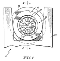
- Fig.1 is an end elevational view of an end cap sizer;
- Fig.2 is a sectional view taken along line 2-2 of Fig.1;
- Fig.3 is a block diagram of a control system of the end cap sizer;
- Fig. 4 is a sectional view similar to Fig. 2 showing an exhaust processor body inserted into the end cap sizer and the end cap sizer measuring the exhaust processor body;
- Fig. 5 is a sectional view similar to Fig. 4 showing the end cap sizer releasing the exhaust processor body so that the exhaust processor can be removed from the end cap sizer;
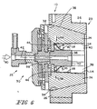
- Fig. 6 is a sectional view similar to Fig. 5 showing an end cap positioned to lie in the end cap sizer and the end cap sizer sizing the end cap so that the end cap will fit into the end of the exhaust processor body measured in Fig. 4;
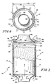
- Fig. 7 is an exploded side elevational view, with portions cutaway, of an exhaust processor having first and second end caps and an exhaust processor body showing the first end cap being positioned to lie away from the exhaust processor body and the first end cap having a crimpable flange that is moved from a first position (solid lines) to a second crimped position (phantom lines) by the end cap sizer shown in Figs. 1-6 so that the first end cap matches the exhaust processor body and the end cap can be pushed into the exhaust processor body;
- Fig. 8 is a top plan view of the first end cap of Fig. 7 showing the crimpable flange in the first position (solid lines) and the second crimped position (phantom fines) after the end cap sizer applies a crimping force to the crimpable flange;
- Fig. 9 is partial side elevational view, with portions cutaway, showing the converter body including a substrate, a mat wrapped around the substrate, and an outer shell wrapped around the mat and substrate and the crimpable flange of the end cap being in its second crimped position and positioned to lie in abutting relation to the mat and substrate;
- Fig. 10 is a sectional view, taken along line 10-10 of Fig. 8, of the end cap;
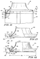
- Fig. 11 is a partial sectional view of the end cap showing a force being applied to the crimpable flange of the end cap to move the crimpable flange to its crimped position;
- Fig. 12 is a partial side elevation view, with portions cutaway, showing a spacer being positioned to lie between the mat and substrate and the end cap;
- Fig. 13 is a sectional view of another embodiment of an end cap showing the end cap having a crimpable flange that differs from the crimpable flange shown in the end cap of Figs. 6-12;
- Fig. 14 is a sectional view of the end cap of Fig. 13 showing a crimping force being applied to the crimpable flange to move the crimpable flange to a crimped position; and
- Fig. 15 is a schematic illustration of another end cap sizer for measuring and sizing components.
-
- An
end cap sizer 10 is shown in Fig. 1. Theend cap sizer 10 sizes anend cap exhaust processor body 12 as shown in Figs. 4-7. The end cap sizer 10sizes end caps end caps end caps 14, 16 a particular size. - The size of
exhaust processor bodies 12 vary within a fairly wide tolerance. Theend cap sizer 10 determines the size of a particularexhaust processor body 12 and then sizes anend cap end cap exhaust processor body 12. Thus,end cap sizer 10 creates a matched pair ofend cap exhaust processor body 12 so thatend cap exhaust processor body 12 may be assembled easily. To form a completedexhaust processor 18, twoend caps exhaust processor body 12 as shown, for example, in Fig. 7. It is within the scope of this disclosure to usesizer 10 to size components other than end caps to fit within bodies configured to receive such components. - The invention is especially, but not exclusively, suitable for use in the production of
exhaust processors 18. In this application, the words "exhaust processor" are intended to refer to various types of diesel particulate filters and other traps, purifiers or substrates in connection with which this invention may be used. In the illustrated embodiment, the words "exhaust processor" specifically refer to a catalytic device (for example, a catalytic converter or a catalytic trap) for use with gasoline engines. -
End cap sizer 10 includes aframe 20, adevice 23 that obtains a body measurement of abody 12 and sizes anend cap control system 25 that movesdevice 23 to the necessary positions to receivebody 12 andend cap exhaust processor body 12, andsize end cap device 23 is a single tool that includes measurer andsizer jaws 24 and astationary portion 26 mounted onframe 20.Control system 25 includes anactuator 28, amechanical linkage 30 that connectsactuator 28 andjaws 24, and aposition controller 27 as shown, for example, in Figs. 1-3. - Movement of
actuator 28 causesjaws 24 to open or close asjaws 24 move relative tostationary portion 26. Thestationary portion 26 is mounted or fixed toframe 20 so that movement ofactuator 28 andjaws 24 do not cause movement ofstationary portion 26.Actuator 28 is a hydraulic power input cylinder.Actuator 28 could be any type of mechanism that causesjaws 24 to open and close such as, for example, any of various electric, hydraulic, or pneumatic mechanisms.Mechanical linkage 30 can be any type of linkage that connectsjaws 24 andactuator 28. -
Stationary portion 26 is formed to include a cone-shapedinner surface 32 that defines anopening 34 through whichjaws 24 are moved byactuator 28. Theframe 20 may be formed to include a jaw-receiving opening so that a separate stationary portion is not required. - The
jaws 24 include a cone-shapedouter surface 36 that abuts cone-shapedinner surface 32 ofstationary portion 26. Movement ofjaws 24 through opening 34 defined byinner surface 32 causesjaws 24 to open and close about alongitudinal axis 42 ofend cap sizer 10. Theouter surface 36 ofjaws 24 andinner surface 32 ofstationary portion 26 may be of any shape that permitjaws 24 to open and close asjaws 24 move throughopening 32 formed instationary portion 26. - The
jaws 24 further include aninner surface 38 that defines acavity 40 sized to receive anexhaust processor body 12 or anend cap exhaust processor body 12, andsize end cap inner surface 38 ofjaws 24 moves outwardly indirection 43 and inwardly indirection 45 relative tolongitudinal axis 42 asjaws 24 open and close, respectively. Thejaws 24 perform the different functions of receiving thebody 12 orcap body 12, and sizingend cap jaws 24 are moved relative tostationary portion 26. Thejaws 24 receive thebody 12 orcap 14 byactuator 28 openingjaws 24 indirection 43 so thatbody 12 orcap 14 fit intocavity 40 defined byinner surface 38 ofjaws 24. Thejaws 24 measurebody 12 byactuator 28closing jaws 24 indirection 45 so thatinner surface 38 ofjaws 24abuts body 12. Thejaws 24size end cap actuator closing jaws 24 indirection 45 so thatinner surface 38 ofjaws 24 compressesend cap - The
position controller 27 ofend cap sizer 10 controls the movement ofactuator 28 andjaws 24 relative tostationary portion 26. Theposition controller 27 also controls the amount of pressure applied byactuator 28 andjaws 24 to endcap exhaust processor body 12. Theposition controller 27 includes aposition sensor 66, aposition memory controller 68, ahydraulic power pack 70, and a plurality ofvalves Position memory controller 68 opens and closesvalves actuator 28 andjaws 24 relative tostationary portion 26. - The
hydraulic power pack 70 includes a high-pressure system 82 and a low-pressure system 84. Each of the high and low-pressure systems control system 25. - The
end caps exhaust processor body 12 according to the following method. First, anend 86 ofexhaust processor body 12 is inserted intocavity 40 defined byinner surface 38 ofjaws 24. As shown in Fig. 4, the actuator 28advances jaws 24 indirection 90 throughopening 34 formed instationary portion 26 to closejaws 24 indirection 45 untilinner surface 38 ofjaws 24 abuts anouter surface 92 ofexhaust processor body 12. - The
position memory controller 68 opensvalves valve 74 so that the low-pressure system 84moves actuator 28 and thusjaws 24 relative tostationary portion 26. The low-pressure system 84 is used so thatjaws 24 only touchouter surface 92 ofexhaust processor body 12 to measure anouter diameter 22 ofexhaust processor body 12 and do not significantly deform any portion ofexhaust processor body 12. If desired, the low pressure may be sufficient to smooth out any rough surface deformation if, for example,exhaust processor body 12 is slightly non-circular. Using a measurement taken byposition sensor 66, theposition memory controller 68 memorizes the position ofactuator 28 andjaws 24. Next, theposition memory controller 68closes valves valves cylinder 28 andjaws 24 retract indirection 94 so thatjaws 24 open indirection 43 to release theexhaust processor body 12 to permit a user to removeexhaust processor body 12 fromend cap sizer 10 as shown in Fig. 5. -
End cap sizer 10 further includes aprojection 96 having afirst end 98 coupled tomechanical linkage 30 and asecond end 110 spaced apart and positioned to lie incavity 40 formed injaws 24. As shown in Fig. 6,end cap projection 96 to assist in centeringend cap cavity 40. Theend cap cavity 40 formed injaws 24 andactuator 28 andjaws 24 are advanced indirection 90 under high pressure so thatjaws 24 close indirection 45 aroundend cap -
Position memory controller 68 opensvalves valves pressure system 82 to supply high-pressure fluid toactuator 28. The high-pressure fluid is used to provide the necessary force forjaws 24 to sizeend cap position memory controller 68 cooperates withposition sensor 66 to moveactuator 28 and thusjaws 24 to the position previously memorized byposition memory controller 68 for the measurement ofend 86 ofexhaust processor body 12. By returningjaws 24 to this same position, thejaws 24size end cap end 86 ofexhaust processor body 12 previously measured. - Once
end cap actuator 28 andjaws 24 retract indirection 94 so thatjaws 24 open indirection 43 and an operator may removeend cap end cap sizer 10. More specifically, the position memory controller opensvalves valves actuator 28 andjaws 24 to retract indirection 94. - The process of measuring
end 86 ofexhaust processor body 12 and sizing anend cap 14 accordingly is repeated for anopposite end 88 ofexhaust processor body 12 and itsmating end cap 16. The end caps 14, 16 cannot be sized based on the measurement of only oneend exhaust processor body 12 because of potential dimensional differences between theends exhaust processor body 12. - The steps of measuring
converter body 12 and sizingend cap end cap converter body 12 is measured orconverter body 12 may be measured and information relating to the sizing measurement may be stored and later used to sizeend cap - The step of measuring
exhaust processor body 12 may be performed using a mechanical device, laser measurement device, proximity measurement device, or any other type of measurement device that can measure a diameter ofexhaust processor body 12. The step of sizingend cap end cap - As shown in Fig. 7,
exhaust processor body 12 includes asubstrate 15, amat 17, and anouter shell 31.Substrate 15 is a ceramic substrate that has a contour tolerance of ± 0.8mm which gives the exhaust processor body 12 a variableouter diameter 22 range of 3.2mm. Thesubstrate 15 may be made of a metal material or other appropriate material. Themat 17 will also vary with a tolerance of ± 10%, for example, for an intumescent mat. The combination of these variables for a final assembly with a 3100 g/m2 and 118.4mm diameter substrate 15 provides anexhaust processor body 12diameter 22 range of 122.2mm to 126.6mm. Theend cap sizer 10 enables end caps 14, 16 to be made to an optimum size to suit each uniqueexhaust processor body 12. -
Exhaust processor 18 is formed when end caps 14, 16 are coupled toexhaust processor body 12. A method and apparatus for producing an exhaust processor is disclosed in U.S. Provisional Application No. 60/074,856 filed February 17, 1998.Exhaust processor 18 is placed in a vehicle exhaust system (not shown) so that exhaust gas flows indirection 19 throughsubstrate 15. Thesubstrate 15 cleans the exhaust gas before the exhaust gas is discharged to the atmosphere. - As shown in Fig. 7, end caps 14, 16 slide into the
exhaust processor body 12 and abut aninner surface 112 ofouter shell 31.Inner surface 112 of outer shell 3 1 defines anend cap region 121 at eachend exhaust processor body 12. Theinner surface 112 of outer shell also defines aninner diameter 122 which dictates the size of theend cap exhaust processor body 12. As discussed above,jaws 24 measure theouter diameter 22 of theouter shell 31 instead of theinner diameter 122 ofinner surface 112. Theend cap sizer 10 accounts for the thickness (difference between the inner andouter diameters 112, 22) ofouter shell 31 ofexhaust processor body 12 becauseend cap end cap region 121 ofexhaust processor body 12 defined byinner surface 112 of outer shell 3 1 as shown in Fig. 7. - The
end cap sizer 10 includes two means for accounting for the thickness ofouter shell 31. First, theposition memory controller 68 may compensate for theouter shell 31 thickness by movingactuator 28 andjaws 24 further forward indirection 90 whenjaws 24 are sizingend cap further jaws 24 move indirection 90, themore jaws 24 close indirection 45 to further compressend cap inner surface 38 ofjaws 24 includes afirst region 114 having afirst diameter 116 and asecond region 118 having asecond diameter 120 that is less thanfirst diameter 116 as shown, for example, in Fig. 5. Theexhaust processor body 12 is measured by the larger diameterfirst region 114 andend cap second region 118. Theexhaust processor body 12 cannot extend intosecond region 118 becausesubstrate 15 abutssecond end 110 ofprojection 96 whenexhaust processor body 12 is inserted intocavity 40 as shown in Fig. 4. Either or both of above-mentioned means for accounting forouter shell 31 thickness may be used. - Referring to Fig. 7, each
end cap annular flange 44 that extends intoexhaust processor body 12, a pipe-mating end 46 spaced apart fromcrimpable flange 44, and a flaredbody portion 48 extending betweencrimpable flange 44 and pipe-mating end 46 as shown, for example, in Figs. 7-12.Crimpable flange 44 includes annular first andsecond portions rounded end 54 extending between first andsecond portions end cap crimpable flange 44 is deformed and moved from a solid-line position to, for example, a phantom-line position as shown in Fig. 7 wherein the phantom-line position is determined by the diametrical size of the portion ofexhaust processor body 12 embracingcrimpable flange 44. - When
end cap exhaust processor body 12,first portion 50 ofcrimpable flange 44 engagesinner surface 112 ofouter shell 31 androunded end 54 ofcrimpable flange 44 abuts axially outer ends ofmat 17 andsubstrate 15 as shown for example, in Fig. 7.Second portion 52 ofcrimpable flange 44 is appended tobody portion 48 ofcrimpable flange 44.Body portion 48 has a horn-like shape, annular first andsecond portions rounded end 54 has a rolled, ring-like shape. - The
end cap sizer 10sizes end cap end cap processor body 12 by applying a crimping force tocrimpable flange 44. The crimping force includes a radially-inwardly directedforce 58 applied byinner surface 38 ofjaws 24 tofirst portion 50 ofcrimpable flange 44 that movesfirst portion 50 ofcrimpable flange 44 towardsecond portion 52 ofcrimpable flange 44 as shown, for example, in Fig. 6. - The
end cap end cap processor body 12. Before the crimpingforce 58 is applied tocrimpable flange 44,end cap diameter 60 that is too large to fit intoexhaust processor body 12. After crimpingforce 58 is applied tocrimpable flange 44,end cap diameter 62 that matches (i.e. corresponds to)inner diameter 122 ofouter shell 31 ofexhaust processor body 12 so thatend cap end cap region 121 ofexhaust processor body 12. -
Crimpable flange 20 includes awidth 49 in the uncrimped position as shown, for example, in Fig. 10. When crimpingforce 58 is applied tofirst portion 26 andcrimpable flange 20 is moved to a crimped position, as shown in Fig. 11,crimpable flange 20 includes awidth 51 that is smaller than itsuncrimped width 49. Thewidth 51 is selected so thatend cap 10 includes adiameter 62 that matches (i.e. corresponds to)inner diameter 122 ofouter shell 31 ofexhaust processor body 12 so thatend cap 10 can be pushed intoend cap region 121 ofexhaust processor body 12. The first andsecond portions crimpable flange 44 may be sized in any suitable manner. - The
position controller 27 ofend cap sizer 10 adjusts the amount of crimpingforce 58 applied to crimpable flange 44) to account for "spring-back" offirst portion 50 ofcrimpable flange 44 afterend cap end cap sizer 10. This adjustment for spring-back may allow for minor variations in material properties ofend cap outer shell 31 described above. For example, the different diameter first andsecond regions inner surface 38 ofjaws 24 may be used to account for "spring-back" by measuringexhaust processor body 12 using thelarger diameter region 114 and sizingend cap 10 using thesmaller diameter region 118. In addition, theactuator 28 may movejaws 24 further indirection 90 so thatjaws 24 close further indirection 45 aroundend cap - Because
end cap mat 17 andsubstrate 15,mat 17 is not exposed to exhaust gas. The sizing ofend cap end cap inner surface 112 ofouter shell 31. This nonexistent or small gap betweenend cap outer shell 31permits end cap outer shell 31. Aspacer 56 such as "sizing paper" may be placed onmat 16 andsubstrate 18 or on the end ofcrimpable flange 44 to set or otherwise fix the axial distance betweenend cap 10 andmat 17 andsubstrate 15. Whenend cap 10 abutsmat 17 andsubstrate 15,mat 17 is not exposed to mat-degrading exhaust gas passing throughexhaust processor body 12. Whenend cap 10 is slightly spaced apart frommat 17 andsubstrate 15,mat 17 is isolated from the mat-degrading exhaust gas passing throughexhaust processor body 12 to the extent thatmat 17 will not be damaged by the exhaust gas. - The
crimpable flange 44 is configured so that a crimpingforce second portions crimpable flange 44 to obtain the desireddiameter 62 ofend cap 14 that matches (i.e. corresponds to)inner diameter 122 ofexhaust processor body 12 as shown in Fig. 11. In one embodiment of the present invention, thesecond portion 52 ofcrimpable flange 44 is held stationary by a first mechanism (not shown) while a second mechanism (not shown) movesfirst portion 50 ofcrimpable flange 44 towardsecond portion 52.Second portion 52 ofcrimpable flange 44 is flat and includes alength 53 to permit a mechanism or tool (not shown) to engagesecond portion 52 easily and holdsecond portion 52 stationary as another mechanism (not shown) engagesfirst portion 50 ofcrimpable flange 44 and movesfirst portion 50 towardsecond portion 52 as shown in Figs. 11. - Another
end cap 130 is shown in Figs. 13 and 14.End cap 130 is identical to endcap 14 shown in Figs. 6-12 except thatend cap 130 includes acrimpable flange 132 that includes afirst portion 134 that is different thanfirst portion 50 ofcrimpable flange 44 ofend cap 14.Crimpable flange 130 includes asecond portion 136 androunded end 138 that are identical tosecond portion 52 androunded end 54 ofcrimpable flange 44.First portion 134 includes first andsecond walls first portion 50 ofcrimpable flange 44,first portion 134 provides a different gripping surface for a crimping machine (not shown) to engage and a different gripping surface for contact with theinner surface 112 ofouter shell 31. -
Crimpable flange 132 includes aheight 144 and awidth 146 in the uncrimped position. When a crimpingforce second portions crimpable flange 132 is moved to a crimped position, as shown in Fig. 14 (solid lines),crimpable flange 132 includes aheight 148 that is greater thanheight 144 and awidth 150 that is smaller thanwidth 146. Thewidth 150 is selected so thatend cap 130 includes adiameter 152 that matches (i. e. corresponds to)inner diameter 122 ofouter shell 31 ofexhaust processor body 12 so thatend cap 130 can be pushed intoend cap region 121 ofexhaust processor body 12. - The
end cap sizer 10 and method of measuringexhaust processor body 12 and sizingend caps exhaust processor body 12 and sizes endcaps exhaust processor body 12. Theend cap sizer 10 and method of measuringexhaust processor body 12 and sizingend caps exhaust processor bodies 12 that are not perfectly round or oval. By usingjaws 24 configured to define an appropriateinterior cavity 40, any shape ofexhaust processor body 12 andend cap - Another
end cap sizer 170 is shown in Fig. 15. Theend cap sizer 170 includes adevice 171 that obtains a body measurement of abody 12 and sizes anend cap control system 173 that movesdevice 171 to the necessary positions to receivebody 12 andend cap exhaust processor body 12, andsize end cap device 171 includes an end cap manipulator orend cap jaws 174, a separate exhaust processor body measurer orbody measure jaws 176, jaw supports 178 connected to endcap jaws 174 andbody measure jaws 176, and a reducing plate orjaw actuation plate 184. Thecontrol system 173 includes aload cell 172, anactuator 180, and amechanical linkage 182. - The
device 171 ofend cap sizer 170 includes separate end cap manipulator orjaws 174 and body measure device orjaws 176. Thebody measure jaws 176 andend cap jaws 174 are common reducing machines that are tooled with a set of outside jaws. To size anend cap exhaust processor body 12, anend cap end cap jaws 174 and anexhaust processor body 12 is placed inbody measure jaws 176. Thecontrol system 173 closes thebody measure jaws 176 to a given force aboutexhaust processor body 12 to measureexhaust processor body 12. Thebody measure jaws 176 communicate withend cap jaws 174 so thatbody measure jaws 176 determine the shape ofexhaust processor body 12 and send information about the exhaust processor body shape to endcap jaws 174 so thatend cap jaws 174 can sizeend cap exhaust processor body 12. -
Body measure jaws 176 andend cap jaws 174 simultaneously measureexhaust processor body 12 and size anend cap exhaust processor body 12 and size anend cap actuator 180 movesjaw actuation plate 184 indirection 186 relative tojaws actuation plate 184 is formed to include taperedside walls second apertures End cap jaws 174 and exhaust processorbody measure jaws 176 are positioned to lie within first andsecond apertures side walls plate 184 moves indirection 186 relative tojaws side walls end cap jaws 174 and exhaustprocessor body jaws 176, respectively, to measureexhaust processor body 12 andsize end cap Actuator 180 movesplate 184 indirection 186 untilload cell 172 measures that a predetermined amount of force is being applied toexhaust processor body 12. -
Actuator 180 is a hydraulic power input cylinder.Actuator 180 could be any type of mechanism that causesjaws Mechanical linkage 182 can be any type of linkage that couplesjaws actuator 180. - Exhaust
processor body measurer 176 is a conventional reducing machine tooled with a set of outside reducing jaws. Theoutside jaws 176 close to a given force aboutexhaust processor body 12 to measure theexhaust processor body 12. Thejaws 176 may also remove irregularities of shape fromexhaust processor body 12. Theend cap manipulator 174 is a similar reducing machine with outside reducing jaws and inside fingers. - The exhaust
processor body measurer 176 andend cap manipulator 174 account for the thickness ofouter shell 31 1 ofconverter body 12 becauseend cap outer shell 31 ofconverter body 12 as shown in Fig. 7. In addition, spring back of thecrimpable flange 44 ofend cap end cap - The
end cap end cap sizer 170 by performing the following steps: - 1. load
exhaust processor body 12 into exhaustprocessor body jaws 176, - 2.
load end cap end cap jaws 174, - 3.
control system 173 closes exhaustprocessor body jaws 176 andend cap jaws 174 byactuator 180 movingjaw actuation plate 184 indirection 186 relative tojaws - 4. the exhaust
processor body jaws 176 andend cap jaws 174 close until a preset force is detected onexhaust processor body 12 byload cell 172 andend cap jaws 174size end cap exhaust processor body 12 and create amatching end cap exhaust processor body 12, and - 5. when the preset force has been reached,
control system 173 opensjaws exhaust processor body 12 andend cap end cap sizer 170. -
- Although the invention is not limited only to the field of sizing end caps to fit exhaust processor bodies, this is an application for which the invention is especially suitable, as it can effectively size the end caps to fit each unique exhaust processor body.
Claims (21)
- A method for use in the production of exhaust processors, the method comprising the steps of:-providing a body (12) having an open end (86, 88) and an end cap (14, 16) having an oversize crimpable portion,measuring the body (12) to obtain a body measurement indicative of the size of the open end (86, 88) of the body, andcrimping the end cap (14, 16) to a size related to the body measurement.
- The method of claim 1, wherein the end cap (14, 16) includes a crimpable flange (44,132) and the step of crimping the end cap (14, 16) to a size related to the body measurement includes the step of compressing the flange (44, 132).
- The method of claim 2, wherein the crimpable flange (44, 132) includes first and second portions (50, 52, 134, 136) and the step of compressing the flange includes the step of moving the first and second portions (50, 52, 134, 136) relative to each other.
- The method of claim 1, wherein the step of crimping the end cap (14, 16) to a size related to the body measurement includes the step of radially compressing the end cap (14, 16)
- The method of claim 1, wherein the body (12) includes an outer shell (31) and the measuring step includes the step of measuring the size of the outer shell (31).
- The method of claim 5, wherein the outer shell (31) includes an outer surface having an outer diameter (22) and an inner surface (112) having an inner diameter (122) and the measuring step includes the step of measuring the outer diameter.
- The method of claim 6, wherein the step of crimping the end cap (14, 16) to a size related to the body measurement includes the step of working the end cap (14, 16) to fit within a region (121) defined by the inner surface of the outer shell.
- The method of claim 6, wherein the end cap includes a crimpable flange (44, 132) and the step of crimping the end cap (14, 16) to a size related to the body measurement includes the step of compressing the crimpable flange (44, 132) to fit within a region defined by the inner surface of the outer shell (31).
- The method of anycreceding claim, further comprising the step of coupling the end cap (14, 16) to the open end (86, 88) of the body (12).
- An end cap sizer (10, 170) for sizing end caps to mate with a body, the end cap sizer including:-a device (23, 171), anda control system (25, 173) configured to move the device (23, 171) to a body measurement position to obtain a body measurement of a body (12) and move the device to a position to size an end cap (14, 16) based on the body measurement.
- The method of claim 1, wherein the measuring step includes the step of advancing jaws (24) against the body (12), and the crimping step includes the step of advancing the jaws (24) against the oversize crimpable portion subsequent to advancing the jaws (24) against the body (12).
- The method of claim 11, wherein the measuring step includes the step of memorizing position information when the jaws (24) are advanced against the body (12) to a jaws position, and the step of advancing the jaws (24) against the oversize crimpable portion include the step of using the position information to advance the jaws (24) back to the jaws position to compress the crimpable portion.
- The method of claim 1, wherein the measuring step and step of crimping the end cap (14, 16) to a size related to the body measurement occur simultaneously.
- The method of claim 13, wherein the measuring step includes the step of advancing body measure jaws (176) against the body, and the step of crimping the end cap to a size related to the body measurement includes the step of advancing end cap jaws (174) against the oversize crimpable portion until detection of a predetermined force on the body (12).
- The end cap sizer (170) of claim 10, wherein the device includes a body measure device adapted to cooperate with the control system to obtain the body measurement and a separate end cap manipulator adapted to cooperate with the control system to compress a crimpable flange of the end cap based on the body measurement.
- The end cap sizer (10, 170) of claim 15, wherein the control system includes an actuator (28, 180) and a mechanical linkage (30, 182) coupling the actuator to the body measure device and the end cap manipulator.
- The end cap sizer (10, 170) of claim 15, wherein the control system is adapted to operate the body measure device and end cap manipulator simultaneously.
- The end cap sizer (170) of claim 15, wherein the body measure device includes a pair of body measure jaws (176) movable to contact the body to obtain the body measurement, the end cap manipulator includes a pair of end cap jaws (174) movable to compress the crimpable flange, and the device includes an actuator (180) to move the body measure jaws and the end cap jaws.
- The end cap sizer (10) of claim 10, wherein the device is adapted to measure the body (12) and to compress a crimpable flange (44, 132) of the end cap (14, 16) based on the body measurement sequentially.
- The end cap sizer of claim 19, wherein the device includes a stationary portion (26), an actuator (28), and a pair of jaws (24) movable along the stationary portion to contact the body (12) to obtain the body measurement and to compress the crimpable flange (44, 132) in response to operation of the actuator.
- The method of claim 1 in which an end cap sizer (10, 170) is provided to measure the body (12) to obtain the body measurement and to crimp the end cap (14, 16).
Applications Claiming Priority (9)
| Application Number | Priority Date | Filing Date | Title |
|---|---|---|---|
| US6129197P | 1997-10-07 | 1997-10-07 | |
| US6129497P | 1997-10-07 | 1997-10-07 | |
| US61294P | 1997-10-07 | ||
| US61291P | 1997-10-07 | ||
| US7485898P | 1998-02-17 | 1998-02-17 | |
| US7485698P | 1998-02-17 | 1998-02-17 | |
| US74856P | 1998-02-17 | ||
| US74858P | 1998-02-17 | ||
| PCT/US1998/021082 WO1999017905A1 (en) | 1997-10-07 | 1998-10-07 | Method and apparatus for assembling exhaust components |
Publications (3)
| Publication Number | Publication Date |
|---|---|
| EP1024922A1 EP1024922A1 (en) | 2000-08-09 |
| EP1024922A4 EP1024922A4 (en) | 2002-11-20 |
| EP1024922B1 true EP1024922B1 (en) | 2004-12-22 |
Family
ID=27490187
Family Applications (2)
| Application Number | Title | Priority Date | Filing Date |
|---|---|---|---|
| EP98952112A Withdrawn EP1021657A4 (en) | 1997-10-07 | 1998-10-07 | Exhaust processor end cap |
| EP98950970A Expired - Lifetime EP1024922B1 (en) | 1997-10-07 | 1998-10-07 | Method and apparatus for assembling exhaust components |
Family Applications Before (1)
| Application Number | Title | Priority Date | Filing Date |
|---|---|---|---|
| EP98952112A Withdrawn EP1021657A4 (en) | 1997-10-07 | 1998-10-07 | Exhaust processor end cap |
Country Status (8)
| Country | Link |
|---|---|
| US (1) | US6253792B1 (en) |
| EP (2) | EP1021657A4 (en) |
| CN (2) | CN1204996C (en) |
| AT (1) | ATE285512T1 (en) |
| BR (2) | BR9814067C1 (en) |
| CA (2) | CA2305724A1 (en) |
| DE (1) | DE69828302T2 (en) |
| WO (2) | WO1999017905A1 (en) |
Cited By (2)
| Publication number | Priority date | Publication date | Assignee | Title |
|---|---|---|---|---|
| WO2011011893A1 (en) * | 2009-07-30 | 2011-02-03 | Gws Tube Forming Solutions Inc. | Apparatus and method for forming an antipollution device housing |
| DE102014218960A1 (en) * | 2014-09-19 | 2016-03-24 | Eberspächer Exhaust Technology GmbH & Co. KG | Method for producing an exhaust gas converter, tool for a ring press for producing an exhaust gas converter, ring press with this tool and exhaust gas converter produced by means of the ring press |
Families Citing this family (9)
| Publication number | Priority date | Publication date | Assignee | Title |
|---|---|---|---|---|
| US20030086832A1 (en) * | 2001-11-02 | 2003-05-08 | Turek Alan G. | End cones for exhaust emission control devices and methods of making |
| US6814771B2 (en) * | 2001-11-30 | 2004-11-09 | Delphi Technologies, Inc. | Evaporative emissions control device with internal seals |
| US20050229982A1 (en) * | 2004-04-20 | 2005-10-20 | Gonzales Peter D | Pipe inlet/outlet flow enhancement device |
| WO2005115683A1 (en) * | 2004-05-28 | 2005-12-08 | Sango Co., Ltd. | Method of producing metal tubular member |
| DE102004037480A1 (en) | 2004-08-03 | 2006-03-02 | Zeuna-Stärker GmbH & Co KG | A vehicle exhaust gas purification device and method of manufacturing the same |
| US7757484B2 (en) * | 2007-01-31 | 2010-07-20 | Caterpillar Inc. | Exhaust treatment device having flow-promoting end caps |
| WO2009059427A1 (en) * | 2007-11-09 | 2009-05-14 | Gws Tube Forming Solutions Inc. | Apparatus and method for forming an antipollution device housing |
| US10428718B2 (en) * | 2016-05-09 | 2019-10-01 | Tenneco Automotive Operating Company Inc. | Compact inline inlet with integrated cast ring |
| CN107314005B (en) * | 2017-07-18 | 2023-06-23 | 中国联合工程有限公司 | Rectifying structure for dissimilar metal overlaying high-temperature high-pressure pipeline |
Family Cites Families (44)
| Publication number | Priority date | Publication date | Assignee | Title |
|---|---|---|---|---|
| US1302300A (en) * | 1913-01-17 | 1919-04-29 | Titeflex Metal Hose Corp | Muffler. |
| US1996346A (en) * | 1933-06-02 | 1935-04-02 | Mueller Co | Pipe or rod fitting |
| US2264524A (en) * | 1940-02-03 | 1941-12-02 | Adolph A Hale | Method of making mufflers |
| US3159239A (en) | 1962-05-11 | 1964-12-01 | Walker Mfg Co | Muffler |
| US3283402A (en) * | 1963-08-23 | 1966-11-08 | White Metal Rolling & Stamping | Methods for fabricating lightweight metal ladders |
| US3308853A (en) * | 1963-11-06 | 1967-03-14 | Minnesota Mining & Mfg | Constrained ceramics |
| US3702024A (en) * | 1969-11-10 | 1972-11-07 | Omark Industries Inc | Method of lining metallic walled carriers |
| US4335077A (en) | 1972-03-21 | 1982-06-15 | Zeuna-Staerker Kg | Catalyzer for detoxifying exhaust gases from internal combustion engines |
| US4344922A (en) | 1972-03-21 | 1982-08-17 | Zeuna-Staerker Kg | Catalyzer for detoxifying exhaust gases from internal combustion |
| US4344921A (en) | 1972-03-21 | 1982-08-17 | Zeuna-Staerker Kg | Catalyzer for detoxifying exhaust gases from internal combustion engines |
| GB1437114A (en) | 1972-09-23 | 1976-05-26 | Daimler Benz Ag | Exhaust pipe apparatus comprising a catalyst element |
| GB1453439A (en) | 1973-01-13 | 1976-10-20 | Ti Silencer Services Ltd | Catalytic reactor for exhaust emission control |
| US3972687A (en) | 1974-03-21 | 1976-08-03 | Paul Gillet Gmbh | Catalytic converter having pressurized-gas support means |
| US3948611A (en) * | 1974-06-10 | 1976-04-06 | Engelhard Minerals & Chemicals Corporation | Catalytic converter having hollow, gas-filled mounting means for a monolithic catalyst |
| DE2434102A1 (en) | 1974-07-16 | 1976-02-05 | Volkswagenwerk Ag | CATALYST FOR THE CATALYTIC CLEANING OF EXHAUST GASES |
| US3934618A (en) * | 1974-08-26 | 1976-01-27 | Controls Southeast, Inc. | Jacketed pipe assembly formed of corrugated metal tubes |
| JPS5817335B2 (en) | 1975-04-10 | 1983-04-06 | トヨタ自動車株式会社 | Method for manufacturing integrated catalyst component for exhaust gas purification |
| US4160010A (en) | 1976-05-28 | 1979-07-03 | J. Eberspacher | Device for purifying exhaust gases |
| US4155980A (en) | 1976-06-19 | 1979-05-22 | Zeuna-Starker Kg | Apparatus for catalytic purifying the effluent gases of internal combustion engines |
| DE2723532C3 (en) | 1977-05-25 | 1980-04-03 | Zeuna-Staerker Kg, 8900 Augsburg | Device for detoxifying exhaust gases from internal combustion engines in motor vehicles |
| DE2805562C2 (en) | 1978-02-10 | 1984-08-02 | Kuka Schweissanlagen + Roboter Gmbh, 8900 Augsburg | Device for welding a workpiece with a tubular cross-section at the welding point to a second workpiece |
| GB2020190A (en) * | 1978-05-04 | 1979-11-14 | Ti Silencers Ltd | Constructing a catalyst assembly |
| DE2856030C2 (en) | 1978-12-23 | 1987-02-12 | Süddeutsche Kühlerfabrik Julius Fr. Behr GmbH & Co KG, 7000 Stuttgart | Method for producing a carrier matrix wound from metal foils for an exhaust gas cartridge |
| JPS5724886Y2 (en) | 1979-03-19 | 1982-05-29 | ||
| US4347219A (en) | 1979-12-29 | 1982-08-31 | Honda Giken Kogyo Kabushiki Kaisha | Catalytic converter for exhaust-gas cleaning use and method of assembling same |
| DE3430398C2 (en) | 1984-08-17 | 1987-04-02 | Voest-Alpine St. Aegyd AG, St. Aegyd am Neuwalde | Catalytic exhaust gas purification device and method for its manufacture |
| US4574455A (en) * | 1984-09-04 | 1986-03-11 | Allied Corporation | Method of manufacturing a shell with an integral reinforcing plate |
| US4969264A (en) | 1986-06-12 | 1990-11-13 | Tennessee Gas Pipeline Company | Catalytic converter and substrate support |
| US5118476A (en) | 1986-06-12 | 1992-06-02 | Tennessee Gas Pipeline Company | Catalytic converter and substrate support |
| US4782570A (en) | 1987-11-16 | 1988-11-08 | General Motors Corporation | Fabrication and assembly of metal catalytic converter catalyst substrate |
| US5145539A (en) | 1988-09-22 | 1992-09-08 | Ngk Insulators, Inc. | Method of producing a honeycomb structural body having at least one step protruded from or recessed in at least one portion of an outer circumferential surface thereof |
| US5345672A (en) * | 1989-03-17 | 1994-09-13 | Motor Wheel Corporation | Brake drum manufacture |
| US4930459A (en) * | 1989-07-21 | 1990-06-05 | Sdi Operating Partners, L.P. | Freeze plug |
| US5183299A (en) * | 1991-10-24 | 1993-02-02 | Robert Hallerstrom | Insulated pipe with end protection |
| JP2659504B2 (en) | 1991-12-26 | 1997-09-30 | 大阪瓦斯株式会社 | Catalytic combustion device |
| DE4244315C2 (en) | 1992-08-31 | 1998-02-26 | Zeuna Staerker Kg | Catalytic emission control device |
| US5408828A (en) | 1993-12-10 | 1995-04-25 | General Motors Corporation | Integral cast diffuser for a catalytic converter |
| DE59408821D1 (en) | 1993-12-31 | 1999-11-18 | Eberspaecher J Gmbh & Co | Exhaust treatment device |
| EP0681095B1 (en) * | 1994-05-02 | 1997-11-05 | LEISTRITZ AG & CO. Abgastechnik | Method and device for mounting an exhaust gas catalyst |
| JPH0842333A (en) | 1994-06-06 | 1996-02-13 | Ford Motor Co | Preparation of catalyst exhaust treating device |
| DE4433974C1 (en) * | 1994-09-23 | 1996-03-28 | Eberspaecher J | Process for the production of catalysts |
| JPH08164432A (en) * | 1994-12-14 | 1996-06-25 | Nippon Steel Corp | Short tube diameter reducing device |
| BR9504071A (en) * | 1995-09-19 | 1997-10-14 | Gillet Heinrich Gmbh | Exhaust gas catalyst for internal combustion engines |
| US6158120A (en) * | 1998-12-14 | 2000-12-12 | General Motors Corporation | Method for making a catalytic converter containing a multiple layer mat |
-
1998
- 1998-10-07 DE DE69828302T patent/DE69828302T2/en not_active Expired - Fee Related
- 1998-10-07 WO PCT/US1998/021082 patent/WO1999017905A1/en not_active Ceased
- 1998-10-07 US US09/529,104 patent/US6253792B1/en not_active Expired - Lifetime
- 1998-10-07 CA CA002305724A patent/CA2305724A1/en not_active Abandoned
- 1998-10-07 BR BR9814067-1A patent/BR9814067C1/en not_active IP Right Cessation
- 1998-10-07 EP EP98952112A patent/EP1021657A4/en not_active Withdrawn
- 1998-10-07 CN CNB988118432A patent/CN1204996C/en not_active Expired - Fee Related
- 1998-10-07 CA CA002305725A patent/CA2305725A1/en not_active Abandoned
- 1998-10-07 AT AT98950970T patent/ATE285512T1/en not_active IP Right Cessation
- 1998-10-07 WO PCT/US1998/021083 patent/WO1999018358A1/en not_active Ceased
- 1998-10-07 EP EP98950970A patent/EP1024922B1/en not_active Expired - Lifetime
- 1998-10-07 BR BR9814063-9A patent/BR9814063A/en not_active IP Right Cessation
- 1998-10-07 CN CNB988118696A patent/CN1242182C/en not_active Expired - Fee Related
Cited By (3)
| Publication number | Priority date | Publication date | Assignee | Title |
|---|---|---|---|---|
| WO2011011893A1 (en) * | 2009-07-30 | 2011-02-03 | Gws Tube Forming Solutions Inc. | Apparatus and method for forming an antipollution device housing |
| US9481025B2 (en) | 2009-07-30 | 2016-11-01 | Gws Tube Forming Solutions Inc. | Apparatus and method for forming an antipollution device housing |
| DE102014218960A1 (en) * | 2014-09-19 | 2016-03-24 | Eberspächer Exhaust Technology GmbH & Co. KG | Method for producing an exhaust gas converter, tool for a ring press for producing an exhaust gas converter, ring press with this tool and exhaust gas converter produced by means of the ring press |
Also Published As
| Publication number | Publication date |
|---|---|
| CN1242182C (en) | 2006-02-15 |
| BR9814067C1 (en) | 2001-10-30 |
| CN1281538A (en) | 2001-01-24 |
| BR9814063A (en) | 2000-09-26 |
| EP1021657A4 (en) | 2002-11-20 |
| CN1204996C (en) | 2005-06-08 |
| ATE285512T1 (en) | 2005-01-15 |
| WO1999018358A1 (en) | 1999-04-15 |
| WO1999017905A1 (en) | 1999-04-15 |
| CA2305725A1 (en) | 1999-04-15 |
| BR9814067A (en) | 2000-09-26 |
| CA2305724A1 (en) | 1999-04-15 |
| EP1024922A1 (en) | 2000-08-09 |
| EP1021657A1 (en) | 2000-07-26 |
| US6253792B1 (en) | 2001-07-03 |
| CN1301207A (en) | 2001-06-27 |
| DE69828302D1 (en) | 2005-01-27 |
| EP1024922A4 (en) | 2002-11-20 |
| DE69828302T2 (en) | 2005-12-08 |
Similar Documents
| Publication | Publication Date | Title |
|---|---|---|
| EP1324853B1 (en) | Apparatus and process for assembling exhaust processor components | |
| US6253792B1 (en) | Exhaust processor end cap | |
| EP0480082B1 (en) | Method and apparatus for contracting a cylindrical body | |
| EP1315592B1 (en) | Hollow member, manufacturing method therof, fluid distribution system using the hollow member, and forming apparatus of hollow member | |
| JP2010209917A (en) | Apparatus and method for manufacturing catalytic converter, gauge assembly for the same and assembly machine including the gauge assembly | |
| CN102177320B (en) | Method for producing an exhaust gas conducting device and tool therefor | |
| US5487327A (en) | Booster housing, especially for vehicle brake systems, and method of assembling such as booster housing | |
| US6463655B1 (en) | Method and apparatus for assembling exhaust components | |
| US6405437B1 (en) | Apparatus and method for encasing an object in a case | |
| US5410903A (en) | Clamp gun crimp head | |
| US20100275443A1 (en) | Method of producing exhaust-gas carrying devices, in particular exhaust-gas cleaning devices | |
| US4871339A (en) | Spark plug crimping die and process | |
| US5775202A (en) | Deformed clamp band made from continuous roll | |
| WO1994018487A1 (en) | Improved hose fitting and method of making | |
| MXPA00003386A (en) | Method and apparatus for assembling exhaust components | |
| WO1996031313A3 (en) | Welding a stack of thin metal sheets | |
| EP1037798B1 (en) | Apparatus for encasing an object in a case | |
| MXPA00003384A (en) | Exhaust processor end cap | |
| JP2950997B2 (en) | Method and apparatus for manufacturing honeycomb body with case, particularly catalyst carrier | |
| CA2256153A1 (en) | Tube end-forming method and apparatus | |
| EP1158245A1 (en) | Glow plug for diesel engines and process for its manufacture | |
| JPH0337790Y2 (en) | ||
| US20190301345A1 (en) | Method for the production of an exhaust-gas routing device for a motor vehicle | |
| JPH0538536A (en) | Device for joining metal pipes | |
| HK1067402B (en) | Method and apparatus for manufacturing a catalytic converter |
Legal Events
| Date | Code | Title | Description |
|---|---|---|---|
| PUAI | Public reference made under article 153(3) epc to a published international application that has entered the european phase |
Free format text: ORIGINAL CODE: 0009012 |
|
| 17P | Request for examination filed |
Effective date: 20000508 |
|
| AK | Designated contracting states |
Kind code of ref document: A1 Designated state(s): AT BE CH CY DE DK ES FI FR GB GR IE IT LI LU MC NL PT SE |
|
| RAP1 | Party data changed (applicant data changed or rights of an application transferred) |
Owner name: ARVINMERITOR, INC. |
|
| A4 | Supplementary search report drawn up and despatched |
Effective date: 20021007 |
|
| AK | Designated contracting states |
Kind code of ref document: A4 Designated state(s): AT BE CH CY DE DK ES FI FR GB GR IE IT LI LU MC NL PT SE |
|
| RIC1 | Information provided on ipc code assigned before grant |
Free format text: 7F 01N 7/18 A, 7F 01N 3/28 B, 7B 23P 19/04 B, 7B 23Q 17/20 B |
|
| 17Q | First examination report despatched |
Effective date: 20030328 |
|
| GRAP | Despatch of communication of intention to grant a patent |
Free format text: ORIGINAL CODE: EPIDOSNIGR1 |
|
| GRAS | Grant fee paid |
Free format text: ORIGINAL CODE: EPIDOSNIGR3 |
|
| GRAL | Information related to payment of fee for publishing/printing deleted |
Free format text: ORIGINAL CODE: EPIDOSDIGR3 |
|
| GRAS | Grant fee paid |
Free format text: ORIGINAL CODE: EPIDOSNIGR3 |
|
| GRAA | (expected) grant |
Free format text: ORIGINAL CODE: 0009210 |
|
| AK | Designated contracting states |
Kind code of ref document: B1 Designated state(s): AT BE CH CY DE DK ES FI FR GB GR IE IT LI LU MC NL PT SE |
|
| PG25 | Lapsed in a contracting state [announced via postgrant information from national office to epo] |
Ref country code: NL Free format text: LAPSE BECAUSE OF FAILURE TO SUBMIT A TRANSLATION OF THE DESCRIPTION OR TO PAY THE FEE WITHIN THE PRESCRIBED TIME-LIMIT Effective date: 20041222 Ref country code: LI Free format text: LAPSE BECAUSE OF FAILURE TO SUBMIT A TRANSLATION OF THE DESCRIPTION OR TO PAY THE FEE WITHIN THE PRESCRIBED TIME-LIMIT Effective date: 20041222 Ref country code: FI Free format text: LAPSE BECAUSE OF FAILURE TO SUBMIT A TRANSLATION OF THE DESCRIPTION OR TO PAY THE FEE WITHIN THE PRESCRIBED TIME-LIMIT Effective date: 20041222 Ref country code: CH Free format text: LAPSE BECAUSE OF FAILURE TO SUBMIT A TRANSLATION OF THE DESCRIPTION OR TO PAY THE FEE WITHIN THE PRESCRIBED TIME-LIMIT Effective date: 20041222 Ref country code: BE Free format text: LAPSE BECAUSE OF FAILURE TO SUBMIT A TRANSLATION OF THE DESCRIPTION OR TO PAY THE FEE WITHIN THE PRESCRIBED TIME-LIMIT Effective date: 20041222 Ref country code: AT Free format text: LAPSE BECAUSE OF FAILURE TO SUBMIT A TRANSLATION OF THE DESCRIPTION OR TO PAY THE FEE WITHIN THE PRESCRIBED TIME-LIMIT Effective date: 20041222 |
|
| REG | Reference to a national code |
Ref country code: GB Ref legal event code: FG4D |
|
| REG | Reference to a national code |
Ref country code: CH Ref legal event code: EP |
|
| REG | Reference to a national code |
Ref country code: IE Ref legal event code: FG4D |
|
| REF | Corresponds to: |
Ref document number: 69828302 Country of ref document: DE Date of ref document: 20050127 Kind code of ref document: P |
|
| PG25 | Lapsed in a contracting state [announced via postgrant information from national office to epo] |
Ref country code: SE Free format text: LAPSE BECAUSE OF FAILURE TO SUBMIT A TRANSLATION OF THE DESCRIPTION OR TO PAY THE FEE WITHIN THE PRESCRIBED TIME-LIMIT Effective date: 20050322 Ref country code: GR Free format text: LAPSE BECAUSE OF FAILURE TO SUBMIT A TRANSLATION OF THE DESCRIPTION OR TO PAY THE FEE WITHIN THE PRESCRIBED TIME-LIMIT Effective date: 20050322 Ref country code: DK Free format text: LAPSE BECAUSE OF FAILURE TO SUBMIT A TRANSLATION OF THE DESCRIPTION OR TO PAY THE FEE WITHIN THE PRESCRIBED TIME-LIMIT Effective date: 20050322 |
|
| PG25 | Lapsed in a contracting state [announced via postgrant information from national office to epo] |
Ref country code: ES Free format text: LAPSE BECAUSE OF FAILURE TO SUBMIT A TRANSLATION OF THE DESCRIPTION OR TO PAY THE FEE WITHIN THE PRESCRIBED TIME-LIMIT Effective date: 20050402 |
|
| NLV1 | Nl: lapsed or annulled due to failure to fulfill the requirements of art. 29p and 29m of the patents act | ||
| REG | Reference to a national code |
Ref country code: CH Ref legal event code: PL |
|
| ET | Fr: translation filed | ||
| PGFP | Annual fee paid to national office [announced via postgrant information from national office to epo] |
Ref country code: GB Payment date: 20050928 Year of fee payment: 8 |
|
| PG25 | Lapsed in a contracting state [announced via postgrant information from national office to epo] |
Ref country code: IE Free format text: LAPSE BECAUSE OF NON-PAYMENT OF DUE FEES Effective date: 20051007 Ref country code: CY Free format text: LAPSE BECAUSE OF FAILURE TO SUBMIT A TRANSLATION OF THE DESCRIPTION OR TO PAY THE FEE WITHIN THE PRESCRIBED TIME-LIMIT Effective date: 20051007 |
|
| PGFP | Annual fee paid to national office [announced via postgrant information from national office to epo] |
Ref country code: FR Payment date: 20051017 Year of fee payment: 8 |
|
| PLBE | No opposition filed within time limit |
Free format text: ORIGINAL CODE: 0009261 |
|
| STAA | Information on the status of an ep patent application or granted ep patent |
Free format text: STATUS: NO OPPOSITION FILED WITHIN TIME LIMIT |
|
| PG25 | Lapsed in a contracting state [announced via postgrant information from national office to epo] |
Ref country code: MC Free format text: LAPSE BECAUSE OF NON-PAYMENT OF DUE FEES Effective date: 20051031 Ref country code: LU Free format text: LAPSE BECAUSE OF NON-PAYMENT OF DUE FEES Effective date: 20051031 |
|
| PGFP | Annual fee paid to national office [announced via postgrant information from national office to epo] |
Ref country code: DE Payment date: 20051130 Year of fee payment: 8 |
|
| 26N | No opposition filed |
Effective date: 20050923 |
|
| REG | Reference to a national code |
Ref country code: IE Ref legal event code: MM4A |
|
| PGFP | Annual fee paid to national office [announced via postgrant information from national office to epo] |
Ref country code: IT Payment date: 20061031 Year of fee payment: 9 |
|
| PG25 | Lapsed in a contracting state [announced via postgrant information from national office to epo] |
Ref country code: DE Free format text: LAPSE BECAUSE OF NON-PAYMENT OF DUE FEES Effective date: 20070501 |
|
| GBPC | Gb: european patent ceased through non-payment of renewal fee |
Effective date: 20061007 |
|
| REG | Reference to a national code |
Ref country code: FR Ref legal event code: ST Effective date: 20070629 |
|
| PG25 | Lapsed in a contracting state [announced via postgrant information from national office to epo] |
Ref country code: GB Free format text: LAPSE BECAUSE OF NON-PAYMENT OF DUE FEES Effective date: 20061007 |
|
| REG | Reference to a national code |
Ref country code: FR Ref legal event code: TP |
|
| PG25 | Lapsed in a contracting state [announced via postgrant information from national office to epo] |
Ref country code: PT Free format text: LAPSE BECAUSE OF NON-PAYMENT OF DUE FEES Effective date: 20050522 |
|
| PG25 | Lapsed in a contracting state [announced via postgrant information from national office to epo] |
Ref country code: FR Free format text: LAPSE BECAUSE OF NON-PAYMENT OF DUE FEES Effective date: 20061031 |
|
| PG25 | Lapsed in a contracting state [announced via postgrant information from national office to epo] |
Ref country code: IT Free format text: LAPSE BECAUSE OF NON-PAYMENT OF DUE FEES Effective date: 20071007 |