EP1024577A1 - Power system - Google Patents
Power system Download PDFInfo
- Publication number
- EP1024577A1 EP1024577A1 EP97909687A EP97909687A EP1024577A1 EP 1024577 A1 EP1024577 A1 EP 1024577A1 EP 97909687 A EP97909687 A EP 97909687A EP 97909687 A EP97909687 A EP 97909687A EP 1024577 A1 EP1024577 A1 EP 1024577A1
- Authority
- EP
- European Patent Office
- Prior art keywords
- power
- signal
- supply
- secondary battery
- circuit
- Prior art date
- Legal status (The legal status is an assumption and is not a legal conclusion. Google has not performed a legal analysis and makes no representation as to the accuracy of the status listed.)
- Withdrawn
Links
Images

Classifications
-
- H—ELECTRICITY
- H03—ELECTRONIC CIRCUITRY
- H03F—AMPLIFIERS
- H03F1/00—Details of amplifiers with only discharge tubes, only semiconductor devices or only unspecified devices as amplifying elements
- H03F1/02—Modifications of amplifiers to raise the efficiency, e.g. gliding Class A stages, use of an auxiliary oscillation
- H03F1/0205—Modifications of amplifiers to raise the efficiency, e.g. gliding Class A stages, use of an auxiliary oscillation in transistor amplifiers
- H03F1/0211—Modifications of amplifiers to raise the efficiency, e.g. gliding Class A stages, use of an auxiliary oscillation in transistor amplifiers with control of the supply voltage or current
- H03F1/0244—Stepped control
-
- H—ELECTRICITY
- H02—GENERATION; CONVERSION OR DISTRIBUTION OF ELECTRIC POWER
- H02J—ELECTRIC POWER NETWORKS; CIRCUIT ARRANGEMENTS OR SYSTEMS FOR SUPPLYING OR DISTRIBUTING ELECTRIC POWER; SYSTEMS FOR STORING ELECTRIC ENERGY
- H02J7/00—Circuit arrangements for charging or discharging batteries or for supplying loads from batteries
- H02J7/50—Circuit arrangements for charging or discharging batteries or for supplying loads from batteries acting upon multiple batteries simultaneously or sequentially
- H02J7/575—Parallel/serial switching of connection of batteries to charge or load circuit
Definitions
- This invention relates to a power system or the like which supplies DC power to an electronic appliance into which contamination of noises from outside should be avoided as much as possible as in an amplifier for audio.
- amplifiers for audio, etc. which are supplied with power from batteries (that is secondary batteries) with huge capacities, have been proposed, and some have already been introduced for practical use.
- an amplifier for audio, etc. powered by a battery with a huge capacity, which is large in size, is inconvenient in terms of transportability and installation, and in addition when the battery is discharged and the supply of power has been stopped, it will become necessary for the battery to be charged over a comparatively long hours, and during the period the amplifier for audio, and moreover, any audio equipment itself will not become unusable.
- the present invention has been accomplished, by contemplating the above described backgrounds, and the purpose thereof is to provide a power system or the like which does not become very large in terms of size, and in addition does not halt any supply of DC power due to charging after discharge.
- a power system to supply an electronic appliance with a DC power is configured as follows. That is, such a configuration comprises:
- a power system to supply an electronic appliance with a DC power is configured as follows. That is, such a configuration comprises:
- a power system to supply an amplifier for audio with a DC power is configured as follows.
- Such a configuration comprises:
- the fourth invention is configured so that the number of the secondary battery in the power system in the above described first through third inventions is two.
- an amplification system for audio has been configured as follows.
- Such a configuration comprises:
- Such a configuration serves to result in making obtainable not only the above described effect due to usage of the above described power system, but also such an effect that any occurrence of uncomfortable switching noises from speakers originated in switching in connection status by the above described connection switching circuit becomes avoidable.
- the sixth invention is configured so that the number of the secondary battery in the power system in the amplification system for audio according to the fifth invention is two.
- FIG. 1 is a circuit diagram showing a circuit configuration of a preferred power system of the present invention and an amplification system for audio inclusive thereof in a built-in fashion.
- an amplifier for audio 1 is an amplifier which receives an audio signal as an input signal and amplifies this at a predetermined amplifying ratio for outputting.
- a mute circuit 2 is at ordinary time, a circuit portion to which an output of the above described amplifier for audio 1 is inputted, and which sends this to a circuit portion of the subsequent step, and in addition, at the time when a mute instruction signal "a" has been sent in from a driving signal generating circuit 5 described later, mutes the above described input.
- An attenuator 3 is a circuit portion to which the output from the amplifier for audio 1 is inputted, and which attenuates the level thereof to a predetermined value and sends it out.
- a control circuit 4 is a circuit portion to which the signal sent from the above described attenuator 3 (that is, the one obtained by attenuating the output from the amplifier for audio 1) is inputted, and which, as of the time when a predetermined time period has lapsed subject to a switching operation of a connection switching circuit 7 described later, looks into whether or not the audio signal is included in the output of this amplifier for audio 1, and if the audio electric signal is not included there continuously over a fixed time period, sends a signal to indicate such a state to the driving signal generating circuit 5.
- the driving signal generating circuit 5 is a circuit portion which receives the above described signal, and sends out a mute instructing signal "a" to the mute circuit 2, and immediately afterwards sends a connection switching signal "b" to the connection switching circuit 7.
- the connection switching circuit 7 is a circuit portion, which comprises four relays 7A, 7B, 7C, and 7D, and connects either secondary battery 6A or 6B with a charging circuit 8 for charging and connects the other thereof with the amplifier for audio 1 for implementing the supply of DC power to the amplifier for audio 1 and, then receiving the connection switching signal "b" from the driving signal generating circuit 5, causes the party which has been supplying the amplifier for audio 1 with a power so far to undergo charging with the charging circuit 8, and causes the party which has been undergoing charging with the charging circuit 8 so far to be connected with the amplifier for audio 1 so as to cause it to supply the amplifier for audio 1 with power.
- moving contacts of the above described respective relays switch from the state under which the moving contacts are respectively in contact with fixed contacts 7A1, 7B1, 7C1, and 7D1 (the fixed contacts symbolized by black triangles in the drawing) to the state under which the moving contacts are respectively in contact with fixed contacts 7A2, 7B2, 7C2, and 7D2 (the fixed contacts symbolized by white triangles in the drawing), or in backward direction from the state under which the moving contacts are respectively in contact with fixed contacts 7A2, 7B2, 7C2, and 7D2 to the state under which the moving contacts are respectively in contact with fixed contacts 7A1, 7B1, 7C1, and 7D1.
- the moving contacts of the relays 7A and 7B are respectively in contact with the power terminal of the amplifier for audio 1 and with the earth, and the moving contacts of the relays 7C and 7D are respectively in contact with the positive and negative output terminals of the charging circuit 8.
- the secondary batteries 6A and 6B have approximately the same charging-discharging features, and compared with the batteries described in the conventional example, are smaller in terms of capacity as well as size.
- the charging circuit 8 is a circuit portion to which an alternate power is given and which performs its rectifying operation or the like to send it out.
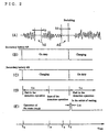
- FIG. 2 is a time chart showing the operation of this power system as well as amplification system for audio, and with reference to this FIG. 2 and FIG. 1 already described, the operation of this power system as well as amplification system for audio will be described as follows.
- the connection switching circuit 7 the moving contacts of the relays 7A and 7B are respectively in contact with the fixed contacts 7A2 and 7B2, and the moving contacts of the relays 7C and 7D are respectively in contact with the fixed contacts 7C2 and 7D2, and consequently the secondary battery 6B is supplying the amplifier for audio 1 with power and the secondary battery 6A is in a state where charging with the charging circuit 8 is taking place.
- connection switching signal "b" if a connection switching signal "b" has been sent in from the driving signal generating circuit 5 to the connection switching circuit 7, the respective moving contacts of the relays 7A, 7B, 7C, and 7D will come into contact with fixed contacts different from the fixed contacts with which they used to be in contact until then, and as shown in FIGS. 2(B) and 2(C), the secondary battery 6A will supply the amplifier for audio 1 with power , and the secondary battery 6B will enter the state of undergoing charging.
- a time period required for completing charging the secondary batteries 6A, 6B is set as the above described fixed time period t s .
- the above described control circuit 4 proceeds with checking on whether or not the above described given signal contains an audio signal, and in the case where the signal is absent for a fixed time period t 0 or longer as indicated by the code AS shown in FIG. 2(A), the circuit detects this and gives a signal expressing such a state to the driving signal generating circuit 5.
- the above described fixed time period t 0 is set up so that it is a little shorter than the duration (generally a several seconds) of absence of sounds at the time when, for example, a piece of music is being followed by another piece of music in the case where a CD (Compact Disc) in which a number of pieces of music are recorded is being replayed.
- the duration generally a several seconds
- the driving signal generating circuit 5 to which the above described signal has been given by the control circuit 4 firstly sends out a mute instructing signal "a" to the mute circuit 2, and immediately thereafter sends out a connection switching signal "b" to the connection switching circuit 7.
- the mute circuit 2 to which the mute instruction signal "a” has been given mutes the output from the amplifier for audio 1 for an extremely short time period t m (see FIG. 2(E)), and during this time period t m , the connection switching circuit 7 which has received the above described connection switching signal "b” implements connection switching and restores the state prior to the point of time T a , and supplies the amplifier for audio 1 with power from the secondary battery 6B and starts charging the secondary battery 6A.
- the power system according to the first through fourth inventions does not become very large in terms of sizes in spite of their using secondary batteries, and in addition, after the secondary battery is completely discharged, the supply of DC power will not be halted at the time of charging the battery.
- a power system is useful for a power for electronic facilities which needs the continuous supply of a DC power.
Landscapes
- Engineering & Computer Science (AREA)
- Power Engineering (AREA)
- Charge And Discharge Circuits For Batteries Or The Like (AREA)
- Direct Current Feeding And Distribution (AREA)
- Amplifiers (AREA)
Abstract
A power system the size of which does not become very large
although the system uses secondary batteries, and in which
the supply of DC power is not stopped at the time of charging
the battery after the secondary battery is completely
discharged, and an amplification system for audio using the
power system. When no signal is inputted to an amplifier (1)
for audio for a fixed period of time or longer, a control
circuit (4) gives a connection switching signal (b) to a
connection switching circuit (7) under a fixed condition,
but, Whenever the signal (b) is given to the circuit (7),
one of the secondary batteries (6A and 6B) is switched to
the power source of the amplifier (1) from a state where the
battery is charged by means of a charging circuit (8), and
the other battery is switched to a state where the battery
is charged by means of the circuit (8) from a state where
the battery supplies electric power to the amplifier (1).
Description
This invention relates to a power system or the like
which supplies DC power to an electronic appliance into which
contamination of noises from outside should be avoided as
much as possible as in an amplifier for audio.
Conventionally, as a power system which supplies DC
power to an electronic appliance such as an amplifier for
audio which dislikes contamination of noises from outside,
there was used such a system that, after accepting the supply
of alternate power, which would be rectified, obtained a
power in the shape of rectified wave, and obtained a direct
current with ripples as little as possible by means of a
smoothing capacitor, a ripple filter circuit, and a
stabilizing circuit, etc., and outputted this.
However, even if the above described power system was
used, any DC power completely without ripples was not
obtainable, and in the case when such a DC power was supplied
to the above described amplifier for audio, noise (hum) due
to the ripples was generated by the amplifier for audio.
Taking the above described background into
consideration, in recent years, amplifiers for audio, etc.,
which are supplied with power from batteries (that is
secondary batteries) with huge capacities, have been
proposed, and some have already been introduced for practical
use.
However, an amplifier for audio, etc., powered by a
battery with a huge capacity, which is large in size, is
inconvenient in terms of transportability and installation,
and in addition when the battery is discharged and the supply
of power has been stopped, it will become necessary for the
battery to be charged over a comparatively long hours, and
during the period the amplifier for audio, and moreover, any
audio equipment itself will not become unusable.
The present invention has been accomplished, by
contemplating the above described backgrounds, and the
purpose thereof is to provide a power system or the like which
does not become very large in terms of size, and in addition
does not halt any supply of DC power due to charging after
discharge.
In a first invention, a power system to supply an
electronic appliance with a DC power is configured as follows.
That is, such a configuration comprises:
The above described configuration makes such a power
system obtainable that does not become very large in terms
of sizes and in addition, for charging the battery after the
time when the secondary battery on duty is completely
discharged, will not halt the supply of DC power to the above
described electronic appliance.
In the second invention, a power system to supply an
electronic appliance with a DC power is configured as follows.
That is, such a configuration comprises:
The above described configuration makes such a power
system obtainable that does not become very large in terms
of sizes, and in addition, for charging the battery after
the time when the secondary battery on duty is completely
discharged, will not halt the supply of DC power to the above
described electronic appliance.
In the third invention, a power system to supply an
amplifier for audio with a DC power is configured as follows.
That is, such a configuration comprises:
The above described configuration makes such a power
system obtainable that does not become very large in terms
of sizes, and in addition, for charging the battery after
the time when the secondary battery on duty is completely
discharged, will not halt the supply of DC power to the above
described amplifier for audio.
The fourth invention is configured so that the number
of the secondary battery in the power system in the above
described first through third inventions is two.
In the fifth invention, an amplification system for
audio has been configured as follows.
That is, such a configuration comprises:
Such a configuration serves to result in making
obtainable not only the above described effect due to usage
of the above described power system, but also such an effect
that any occurrence of uncomfortable switching noises from
speakers originated in switching in connection status by the
above described connection switching circuit becomes
avoidable.
The sixth invention is configured so that the number
of the secondary battery in the power system in the
amplification system for audio according to the fifth
invention is two.
In order to explain and describe the present invention
in further detail, description hereon will be proceeded with
reference to the attached drawings.
FIG. 1 is a circuit diagram showing a circuit
configuration of a preferred power system of the present
invention and an amplification system for audio inclusive
thereof in a built-in fashion. In the drawing, an amplifier
for audio 1 is an amplifier which receives an audio signal
as an input signal and amplifies this at a predetermined
amplifying ratio for outputting. A mute circuit 2 is at
ordinary time, a circuit portion to which an output of the
above described amplifier for audio 1 is inputted, and which
sends this to a circuit portion of the subsequent step, and
in addition, at the time when a mute instruction signal "a"
has been sent in from a driving signal generating circuit
5 described later, mutes the above described input.
An attenuator 3 is a circuit portion to which the output
from the amplifier for audio 1 is inputted, and which
attenuates the level thereof to a predetermined value and
sends it out. A control circuit 4 is a circuit portion to
which the signal sent from the above described attenuator
3 (that is, the one obtained by attenuating the output from
the amplifier for audio 1) is inputted, and which, as of the
time when a predetermined time period has lapsed subject to
a switching operation of a connection switching circuit 7
described later, looks into whether or not the audio signal
is included in the output of this amplifier for audio 1, and
if the audio electric signal is not included there
continuously over a fixed time period, sends a signal to
indicate such a state to the driving signal generating
circuit 5. The driving signal generating circuit 5 is a
circuit portion which receives the above described signal,
and sends out a mute instructing signal "a" to the mute circuit
2, and immediately afterwards sends a connection switching
signal "b" to the connection switching circuit 7.
The connection switching circuit 7 is a circuit portion,
which comprises four relays 7A, 7B, 7C, and 7D, and connects
either secondary battery 6A or 6B with a charging circuit
8 for charging and connects the other thereof with the
amplifier for audio 1 for implementing the supply of DC power
to the amplifier for audio 1 and, then receiving the
connection switching signal "b" from the driving signal
generating circuit 5, causes the party which has been
supplying the amplifier for audio 1 with a power so far to
undergo charging with the charging circuit 8, and causes the
party which has been undergoing charging with the charging
circuit 8 so far to be connected with the amplifier for audio
1 so as to cause it to supply the amplifier for audio 1 with
power. That is, each time the connection switching signal
"b" is sent in, moving contacts of the above described
respective relays switch from the state under which the
moving contacts are respectively in contact with fixed
contacts 7A1, 7B1, 7C1, and 7D1 (the fixed contacts
symbolized by black triangles in the drawing) to the state
under which the moving contacts are respectively in contact
with fixed contacts 7A2, 7B2, 7C2, and 7D2 (the fixed contacts
symbolized by white triangles in the drawing), or in backward
direction from the state under which the moving contacts are
respectively in contact with fixed contacts 7A2, 7B2, 7C2,
and 7D2 to the state under which the moving contacts are
respectively in contact with fixed contacts 7A1, 7B1, 7C1,
and 7D1. Incidentally, the moving contacts of the relays
7A and 7B are respectively in contact with the power terminal
of the amplifier for audio 1 and with the earth, and the moving
contacts of the relays 7C and 7D are respectively in contact
with the positive and negative output terminals of the
charging circuit 8.
The secondary batteries 6A and 6B have approximately
the same charging-discharging features, and compared with
the batteries described in the conventional example, are
smaller in terms of capacity as well as size. The charging
circuit 8 is a circuit portion to which an alternate power
is given and which performs its rectifying operation or the
like to send it out.
FIG. 2 is a time chart showing the operation of this
power system as well as amplification system for audio, and
with reference to this FIG. 2 and FIG. 1 already described,
the operation of this power system as well as amplification
system for audio will be described as follows. For example,
now, suppose in the connection switching circuit 7 the moving
contacts of the relays 7A and 7B are respectively in contact
with the fixed contacts 7A2 and 7B2, and the moving contacts
of the relays 7C and 7D are respectively in contact with the
fixed contacts 7C2 and 7D2, and consequently the secondary
battery 6B is supplying the amplifier for audio 1 with power
and the secondary battery 6A is in a state where charging
with the charging circuit 8 is taking place. In addition,
at the point of time Ta shown in FIG. 2, if a connection
switching signal "b" has been sent in from the driving signal
generating circuit 5 to the connection switching circuit 7,
the respective moving contacts of the relays 7A, 7B, 7C, and
7D will come into contact with fixed contacts different from
the fixed contacts with which they used to be in contact until
then, and as shown in FIGS. 2(B) and 2(C), the secondary
battery 6A will supply the amplifier for audio 1 with
power , and the secondary battery 6B will enter the state of
undergoing charging.
For example, now, suppose the input signal to the
amplifier for audio 1 (equivalent to, that is, the signal
to be given to the control circuit 4 via the attenuator 3)
is identical to that shown in FIG. 2 (A). In this case, the
control circuit 4 in FIG. 1 will not, as shown in FIG. 2 (D),
implement its detecting operation on whether or not any audio
signal is contained in the above described given signal,
until such a point of time Tb when a predetermined fixed time
period ts has lapsed. Accordingly, though in the case where
the portion indicated with the code NS, that is, the audio
signal, in FIG. 2 (A), does not appear for a fixed time period
of to, described later, or longer, the connection switching
operation will not be implemented in the connection switching
circuit 7. A time period required for completing charging
the secondary batteries 6A, 6B is set as the above described
fixed time period ts.
After the point of time Tb when the above described fixed
time period ts has lapsed, the above described control circuit
4 proceeds with checking on whether or not the above described
given signal contains an audio signal, and in the case where
the signal is absent for a fixed time period t0 or longer as
indicated by the code AS shown in FIG. 2(A), the circuit
detects this and gives a signal expressing such a state to
the driving signal generating circuit 5. Incidentally, the
above described fixed time period t0 is set up so that it is
a little shorter than the duration (generally a several
seconds) of absence of sounds at the time when, for example,
a piece of music is being followed by another piece of music
in the case where a CD (Compact Disc) in which a number of
pieces of music are recorded is being replayed.
The driving signal generating circuit 5 to which the
above described signal has been given by the control circuit
4 firstly sends out a mute instructing signal "a" to the mute
circuit 2, and immediately thereafter sends out a connection
switching signal "b" to the connection switching circuit 7.
The mute circuit 2 to which the mute instruction signal "a"
has been given mutes the output from the amplifier for audio
1 for an extremely short time period tm (see FIG. 2(E)), and
during this time period tm, the connection switching circuit
7 which has received the above described connection switching
signal "b" implements connection switching and restores the
state prior to the point of time Ta, and supplies the amplifier
for audio 1 with power from the secondary battery 6B and starts
charging the secondary battery 6A. And subsequently the
above described operation will be repeated. Thus, while one
of secondary batteries 6A and 6B is being used as a power
for the amplifier for audio 1, the other is arranged to undergo
charging, and after this other party has undergone charging
sufficiently, when any audio signal is absent for a fixed
period of time or longer, the output from the amplifier for
audio 1 is muted for an extremely short period of time, during
such a period the secondary battery which has been undergoing
charging until then is placed on duty as a power for the
amplifier for audio 1, and the other party battery starts
undergoing charging, which switching operation will be
repeated. Thus, no such a case will occur that the amplifying
operation of the amplifier for audio 1 must be halted in order
to charge the secondary batteries 6A, 6B. Thus availability
time period of these two secondary batteries may be
comparatively short, and accordingly, the secondary
batteries do not have to be large in terms of capacity, and
moreover the one with smaller sizes will do.
As described in detail so far, the power system according
to the first through fourth inventions does not become very
large in terms of sizes in spite of their using secondary
batteries, and in addition, after the secondary battery is
completely discharged, the supply of DC power will not be
halted at the time of charging the battery. Thus, such a power
system is useful for a power for electronic facilities which
needs the continuous supply of a DC power.
In addition, in the amplification system for audio
according to the fifth invention which the power system
according to the above described third invention is built
in as well as in the amplification system for audio according
to the sixth invention, not only the above described effect
due to usage of the above described power system, but also
such an effect that any occurrence of uncomfortable switching
noises from speakers originated in connection switching by
a connection switching circuit inside the above described
power system can become avoidable can be obtained. Therefore,
such an amplification system for audio is useful as the
amplifier for various audio appliances.
Claims (6)
- A power system for supplying an electronic appliance with DC power characterized by comprising:a plurality of secondary batteries;a detecting circuit on absence of signal which detects whether or not there is any input signal into the above described electronic appliance, and in the case when there is no above-described input signal continuously for a predetermined fixed time period, sends out a detecting signal on absence of signal to indicate such a state;a charging circuit which, after receiving an alternate power, implements the supply of DC power for charging; anda connection switching circuit which connects one of a plurality of said secondary batteries with the above described electronic appliance so that the battery functions a secondary battery for the supply of power to supply said electronic appliance with a DC power, and connects the others with the above described charging circuit so as to function as secondary batteries to be charged, and every time when a detecting signal on absence of a signal is sent out from said detecting circuit on absence of a signal, switches connection status, and causes the one which functioned as said secondary battery for the supply of power up to this point of time to function as said secondary battery to be charged, and causes one of those batteries which functioned said secondary battery to be charged up to said point of time to function as said secondary battery for the supply of power.
- A power system for supplying an electronic appliance with a DC power characterized by comprising:a plurality of secondary batteries;a detecting circuit on absence of signal which, after a predetermined time has lapsed since switching in connection status in the later-described connection switching circuit has taken place, starts detecting whether or not there is any input signal into the above described electronic appliance, and in the case when there is no above-described input signal continuously for a predetermined fixed time period, sends out a detecting signal on absence of signal to indicate such a state;a charging circuit which, after receiving an alternate power, implements the supply of DC power for charging; anda connection switching circuit which connects one of a plurality of said secondary batteries with the above described electronic appliance so that the battery functions a secondary battery for the supply of power to supply said electronic appliance with a DC power, and connects the others with the above described charging circuit so as to function as secondary batteries to be charged, and every time when a detecting signal on absence of a signal is sent out from said detecting circuit on absence of a signal, switches connection status, and causes the one which functioned as said secondary battery for the supply of power up to this point of time to function as said secondary battery to be charged, and causes one of those batteries which functioned said secondary battery to be charged up to said point of time to function as said secondary battery for the supply of power.
- A power system for supplying an amplifier for audio with DC power characterized by comprising:a plurality of secondary batteries;a detecting circuit on absence of signal which, after a predetermined time has lapsed since switching in connection status in the later-described connection switching circuit has taken place, starts detecting whether or not there is any audio input signal into the above described amplifier for audio, and in the case when there is no said audio input signal continuously for a predetermined fixed time period, sends out a detecting signal on absence of signal to indicate such a state;a charging circuit which, after receiving an alternate power, implements the supply of DC power for charging; anda connection switching circuit which connects one of a plurality of said secondary batteries with the above described amplifier for audio so that the battery functions a secondary battery for the supply of power to supply said amplifier for audio with a DC power, and connects the others with the above described charging circuit so as to function as batteries to be charged, and every time when a detecting signal on absence of a signal is sent out from said detecting circuit on absence of a signal, switches connection status, and causes the one which functioned as said secondary battery for the supply of power up to this point of time to function as said secondary battery to be charged, and causes one of those batteries which functioned said secondary battery to be charged up to said point of time to function as said secondary battery for the supply of power.
- The power system according to Claims 1 through 3, wherein the number of said secondary battery is two.
- An amplification system for audio characterized by comprising:the power system according to claim 3;an amplifier for audio which is provided with the power supply by said power system; anda mute circuit to temporarily mute an output from said amplifier for audio at the time when switching in connection status by a connection switching circuit of said power system takes place.
- The amplification system for audio according to Claim 5, wherein the number of said secondary battery for said power system is two.
Applications Claiming Priority (3)
| Application Number | Priority Date | Filing Date | Title |
|---|---|---|---|
| JP27958797A JP3167662B2 (en) | 1997-09-26 | 1997-09-26 | Power system |
| JP27958797 | 1997-09-26 | ||
| PCT/JP1997/003943 WO1999017417A1 (en) | 1997-09-26 | 1997-10-30 | Power system |
Publications (2)
| Publication Number | Publication Date |
|---|---|
| EP1024577A1 true EP1024577A1 (en) | 2000-08-02 |
| EP1024577A4 EP1024577A4 (en) | 2007-05-02 |
Family
ID=17613074
Family Applications (1)
| Application Number | Title | Priority Date | Filing Date |
|---|---|---|---|
| EP97909687A Withdrawn EP1024577A4 (en) | 1997-09-26 | 1997-10-30 | POWER SUPPLY SYSTEM |
Country Status (4)
| Country | Link |
|---|---|
| US (1) | US6268773B1 (en) |
| EP (1) | EP1024577A4 (en) |
| JP (1) | JP3167662B2 (en) |
| WO (1) | WO1999017417A1 (en) |
Cited By (1)
| Publication number | Priority date | Publication date | Assignee | Title |
|---|---|---|---|---|
| EP2582037A1 (en) * | 2011-10-12 | 2013-04-17 | Harman Becker Automotive Systems GmbH | Device and method for reproducing an audio signal |
Families Citing this family (3)
| Publication number | Priority date | Publication date | Assignee | Title |
|---|---|---|---|---|
| ATE434010T1 (en) | 1999-08-27 | 2009-07-15 | Angiodevice Internat Gmbh | INTERPENETRATING POLYMER NETWORK FOR USE AS HIGH STRENGTH MEDICAL SEALANT |
| US20120243696A1 (en) * | 2010-11-11 | 2012-09-27 | Honeywell International Inc. | Supervisory Method and Apparatus for Audio Input Path |
| US20260067138A1 (en) * | 2024-09-05 | 2026-03-05 | Analog Devices International Unlimited Company | Transmit signal squelch at symbol boundaries |
Family Cites Families (14)
| Publication number | Priority date | Publication date | Assignee | Title |
|---|---|---|---|---|
| JPS62277806A (en) * | 1986-05-26 | 1987-12-02 | Nippon Telegr & Teleph Corp <Ntt> | High frequency amplifier |
| US4694237A (en) * | 1986-07-08 | 1987-09-15 | Norand Corporation | Isolated power supply system and method |
| JPH079448Y2 (en) * | 1990-05-02 | 1995-03-06 | アキュフェーズ株式会社 | Muting circuit |
| JPH0530676A (en) * | 1991-07-17 | 1993-02-05 | Matsushita Electric Ind Co Ltd | Power source |
| JPH06245396A (en) * | 1993-02-18 | 1994-09-02 | Fujitsu Ten Ltd | Voltage drop detector for vehicle battery power source |
| BR9405440A (en) * | 1993-06-30 | 1999-09-08 | Motorola Inc | Electronic device releasably connectable to variable-level power source and rechargeable rechargeable power source process. |
| JPH0799731A (en) * | 1993-09-27 | 1995-04-11 | Matsushita Electric Ind Co Ltd | Charge control device |
| JP3103712B2 (en) * | 1994-03-14 | 2000-10-30 | 松下電子工業株式会社 | Power amplifier and amplification method |
| JPH0846562A (en) * | 1994-07-28 | 1996-02-16 | Oki Electric Ind Co Ltd | In-vehicle mobile phone |
| US5614806A (en) * | 1994-11-29 | 1997-03-25 | Wilson; Nathaniel B. | Battery charger |
| JPH0918261A (en) * | 1995-06-27 | 1997-01-17 | Sanyo Electric Co Ltd | Muting circuit for electronic apparatus |
| JPH09121461A (en) * | 1995-10-23 | 1997-05-06 | Hitachi Ltd | Self-rechargeable battery and electrical equipment using the same |
| US6163706A (en) * | 1997-11-18 | 2000-12-19 | Conexant Systems, Inc. | Apparatus for and method of improving efficiency of transceivers in radio products |
| US5898342A (en) * | 1998-01-20 | 1999-04-27 | Advanced Micro Devices | Power amplifier arrangement and method for data signal interface |
-
1997
- 1997-09-26 JP JP27958797A patent/JP3167662B2/en not_active Expired - Lifetime
- 1997-10-30 US US09/508,853 patent/US6268773B1/en not_active Expired - Fee Related
- 1997-10-30 WO PCT/JP1997/003943 patent/WO1999017417A1/en not_active Ceased
- 1997-10-30 EP EP97909687A patent/EP1024577A4/en not_active Withdrawn
Cited By (2)
| Publication number | Priority date | Publication date | Assignee | Title |
|---|---|---|---|---|
| EP2582037A1 (en) * | 2011-10-12 | 2013-04-17 | Harman Becker Automotive Systems GmbH | Device and method for reproducing an audio signal |
| US9780739B2 (en) | 2011-10-12 | 2017-10-03 | Harman Becker Automotive Systems Gmbh | Device and method for reproducing an audio signal |
Also Published As
| Publication number | Publication date |
|---|---|
| EP1024577A4 (en) | 2007-05-02 |
| WO1999017417A1 (en) | 1999-04-08 |
| JP3167662B2 (en) | 2001-05-21 |
| US6268773B1 (en) | 2001-07-31 |
| JPH11103533A (en) | 1999-04-13 |
Similar Documents
| Publication | Publication Date | Title |
|---|---|---|
| US6349223B1 (en) | Universal hand-free system for cellular phones in combination with vehicle's audio stereo system | |
| US8686682B2 (en) | Power supply for battery powered devices | |
| JP2647730B2 (en) | Mobile phone equipment | |
| US6091225A (en) | Battery charging system having a speaker and a mode changing switch | |
| EP1169764B1 (en) | Apparatus and method for automatic recovery of sulfated lead acid batteries | |
| EP1830550B1 (en) | Echo prevention circuit, filter coefficient setting method, and recording medium with program recorded | |
| US6268773B1 (en) | Power system | |
| EP0935836A2 (en) | Portable electronic device and method | |
| JP3830531B2 (en) | Storage battery device for electric and / or electronic device and telecommunication terminal comprising the same | |
| JPH06231806A (en) | Battery pack | |
| EP0545633A1 (en) | Improvements in battery charging | |
| US5977657A (en) | Electric power supply device for producing a plurality of voltages and apparatus comprising such a device | |
| JPH11136784A (en) | Power supply device for plug | |
| US20040164710A1 (en) | Battery charging apparatus | |
| GB2251362A (en) | Speech detection circuit | |
| KR100702321B1 (en) | Codec initialization noise cancellation method of mobile communication terminal and mobile communication terminal for same | |
| JP3066246B2 (en) | Battery display device for electrical equipment | |
| US4096439A (en) | Amplified microphone assembly | |
| CN218941331U (en) | Hearing aid charging circuit with anti-live corrosion function | |
| CN216528039U (en) | Mute switching circuit and audio playing device | |
| JP3751238B2 (en) | Charging stand for rechargeable battery-powered electronic devices | |
| JP2003289632A (en) | Power supply system for electronic equipment | |
| JPS63190518A (en) | Noise eliminater in digital equipment | |
| JPH0117908Y2 (en) | ||
| JPH0583183A (en) | Radio telephone set |
Legal Events
| Date | Code | Title | Description |
|---|---|---|---|
| PUAI | Public reference made under article 153(3) epc to a published international application that has entered the european phase |
Free format text: ORIGINAL CODE: 0009012 |
|
| 17P | Request for examination filed |
Effective date: 20000426 |
|
| AK | Designated contracting states |
Kind code of ref document: A1 Designated state(s): CH DE DK FR GB IT LI NL |
|
| A4 | Supplementary search report drawn up and despatched |
Effective date: 20070404 |
|
| 17Q | First examination report despatched |
Effective date: 20070823 |
|
| STAA | Information on the status of an ep patent application or granted ep patent |
Free format text: STATUS: THE APPLICATION HAS BEEN WITHDRAWN |
|
| 18W | Application withdrawn |
Effective date: 20071026 |