EP1024491A2 - Tape cartridge - Google Patents
Tape cartridge Download PDFInfo
- Publication number
- EP1024491A2 EP1024491A2 EP00300190A EP00300190A EP1024491A2 EP 1024491 A2 EP1024491 A2 EP 1024491A2 EP 00300190 A EP00300190 A EP 00300190A EP 00300190 A EP00300190 A EP 00300190A EP 1024491 A2 EP1024491 A2 EP 1024491A2
- Authority
- EP
- European Patent Office
- Prior art keywords
- tape
- connecting plate
- housing
- hubs
- plate parts
- Prior art date
- Legal status (The legal status is an assumption and is not a legal conclusion. Google has not performed a legal analysis and makes no representation as to the accuracy of the status listed.)
- Granted
Links
- 239000000314 lubricant Substances 0.000 description 5
- 238000010276 construction Methods 0.000 description 2
- 238000013500 data storage Methods 0.000 description 1
- 230000000694 effects Effects 0.000 description 1
- 230000037431 insertion Effects 0.000 description 1
- 238000003780 insertion Methods 0.000 description 1
Images


Classifications
-
- G—PHYSICS
- G11—INFORMATION STORAGE
- G11B—INFORMATION STORAGE BASED ON RELATIVE MOVEMENT BETWEEN RECORD CARRIER AND TRANSDUCER
- G11B23/00—Record carriers not specific to the method of recording or reproducing; Accessories, e.g. containers, specially adapted for co-operation with the recording or reproducing apparatus ; Intermediate mediums; Apparatus or processes specially adapted for their manufacture
- G11B23/02—Containers; Storing means both adapted to cooperate with the recording or reproducing means
- G11B23/04—Magazines; Cassettes for webs or filaments
- G11B23/08—Magazines; Cassettes for webs or filaments for housing webs or filaments having two distinct ends
- G11B23/087—Magazines; Cassettes for webs or filaments for housing webs or filaments having two distinct ends using two different reels or cores
- G11B23/08707—Details
- G11B23/08735—Covers
- G11B23/08742—Covers in combination with brake means
-
- G—PHYSICS
- G11—INFORMATION STORAGE
- G11B—INFORMATION STORAGE BASED ON RELATIVE MOVEMENT BETWEEN RECORD CARRIER AND TRANSDUCER
- G11B23/00—Record carriers not specific to the method of recording or reproducing; Accessories, e.g. containers, specially adapted for co-operation with the recording or reproducing apparatus ; Intermediate mediums; Apparatus or processes specially adapted for their manufacture
- G11B23/02—Containers; Storing means both adapted to cooperate with the recording or reproducing means
- G11B23/04—Magazines; Cassettes for webs or filaments
- G11B23/08—Magazines; Cassettes for webs or filaments for housing webs or filaments having two distinct ends
- G11B23/087—Magazines; Cassettes for webs or filaments for housing webs or filaments having two distinct ends using two different reels or cores
- G11B23/08707—Details
- G11B23/08721—Brakes for tapes or tape reels
Definitions
- This invention relates to tape cartridges, for example for digital recording, such as digital data service (DDS) and digital audio tape (DAT), and other applications. More particularly the invention relates to tape cartridges of the type having brakes for hubs around which a tape is wound.
- DDS digital data service
- DAT digital audio tape
- Tape cartridges in common use comprise housing made up of upper and lower half casings, a pair of hubs around which a length of tape is wound and which are turnably supported within the housing, said lower half casing having a pair of holes through which drive shafts of a recorder/reproducer are inserted to drive the hubs, a slider which slidably covers and uncovers the holes, said slider being disposed along the outer surface of the lower casing, and a hub brake having brake pawls adapted to be engaged with and disengaged from teeth provided around the hubs, said hub brake being disposed slidably within the cartridge housing.
- the hub brake slides to release its pawls out of engagement with the teeth, in an interlocked operation, when the front lid that covers the tape portion pulled out to the front of the upper and lower casings of the housing is turned open.
- Japanese Utility Model Application Kokoku No. 2-49031 discloses a cartridge housing made up of an upper half casing 1 and a lower half casing 2 as illustrated in FIG. 5, wherein a pair of hubs 3 around which a length of tape 4 is wound are turnably supported, said lower casing having a pair of holes through which driving shafts of a recorder/reproducer to drive the hubs 3 are to be inserted, a slider 7 which slidably covers or uncovers the holes is disposed along the outer surface of the lower casing 2, and a hub brake 8 is provided inside the cartridge so as to slide along the inner surface of the upper casing 1, said hub brake having brake pawls 81 adapted to engage teeth 31 formed around the hubs 3, in such manner that the pawls 81 of the hub brake 8 are released against the urging of a spring 9 as the brake is caused to slide in an interlocked operation with the opening of an openable front lid 10 which covers a portion of the tape 4 pulled out to the front of the housing.
- the hub brake 8 with both ends bent at right angles, can slide along the both inner end surfaces of the upper and lower half casings 1, 2.
- Tape cartridges of the type described above are in use for recording audio-frequency signals and data in general. Recent demand for larger and larger memory capacities for data storage has been met by reducing the thickness of tape or increasing the diameter of the tape wound up in a roll.
- the tape roll When such a cartridge is used, the tape roll is unwound to force an expose portion of it ahead at the front of the cartridge. With a large tape roll, it can occur that the tape portion being unwound from the roll is damaged by sliding contact with the inner surface of the hub brake.
- the hub brake 8 has a pair of connecting plate parts 83 at the left and right ends with which the brake can move back and forth along the inner walls of the upper and lower casings.
- the connecting plate parts 83 in turn have arms with projections 85 formed at their front ends, respectively.
- the hub brake 8 is activated as part of the front lid 10 presses the projections 85 when the lid is turned open and closed.
- the tape 4 that is partly pulled out to the front of the housing can sometimes come in contact with part of the connecting plate parts 83 of the hub brake 8 and be damaged by the sliding contact.
- a tape cartridge which comprises a housing which may be made up of upper and lower half casings, a pair of hubs around which a length of tape may be wound and which are turnably supported within the housing.
- a freely openable front lid may be provided at the front of the housing to cover an exposed portion of the tape, and a hub brake may be provided having a pair of brake pawls adapted to be engaged with and disengaged from teeth provided around the hubs, said hub brake preferably being disposed along the inner wall surface of the upper casing within the cartridge housing and normally urged toward the hubs by an elastic member.
- the hub brake may comprise a main face plate part having the brake pawls.
- Connecting plate parts may be perpendicularly bent and extended downwardly from the left and right ends of the main face plate part. Arms may extend frontwardly from the lower ends of the connecting plate parts, and projections may be adapted to be engaged with part of the front lid when the lid is turned open, to force the arms frontwardly. Said connecting plate parts may have recesses, one for each, formed in the rear inner portions thereof facing the exposed tape portion.
- the recesses formed in the rear inner portions of the connecting plate parts are preferably bevels tapering rearwardly and outwardly, but they may take the form of steps instead.
- FIGS. 1 to 4 illustrating an embodiment of the invention.
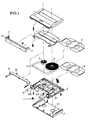
- FIG. 1 is an overall exploded view of a tape cartridge embodying the invention.
- FIGS. 2 to 4 are explanatory views of essential parts of the invention. In FIGS. 2 and 4 lubricant sheets are omitted for a better understanding of the construction.
- the tape cartridge comprises a cartridge housing made up of an upper half casing 1 and a lower half casing 2, a pair of hubs 3 around which a tape 4 is wound and which are turnably supported within the housing, lubricant sheets 5, 6 placed above and below the hubs, said lower casing having a pair of holes 21 through which driving shafts of a recorder/reproducer to drive the hubs 3 are to be inserted, a slider 7 disposed along the outer surface of the lower casing 2 and made slidable to cover or uncover the holes, said slider 7 having a pair of holes 71 which are aligned with the holes 21 when the slider is slid backward to its open position to allow the insertion of the driving shafts, a hub brake 8 disposed between the inner wall of the upper casing and the lubricant sheet inside the cartridge, said hub brake having a pair of brake pawls 81 adapted to engage teeth 31 formed around the hubs 3, and springs 9 by which the hub brake is urged toward the
- the tape 4 is partly extended between front openings 22, 22 at the front of the housing by means of tape guides 23, 23, and when the cartridge is not in use the tape portion 4 exposed outside the housing is covered by the front lid 10 and slider 7.
- the slider 7 When starting the use of the cartridge, the slider 7 is first forced back by drive means on the recorder side, leaving a tape loading area 24 (FIG. 2) exposed. Then the front lid 10 opens. At this moment side lugs 11 of the front lid (FIG. 1) come in contact with the projections 85 at the ends of arms 84 of the hub brake 8 (FIG. 3), forcing the hub brake 8 frontward. This releases the brake pawls 81 out of engagement with the teeth 31, setting the hubs 3 free to turn.
- Tape pull-out pins P (FIG. 2) of a recorder/reproducer then enter the tape loading area 24 and pull out a tape portion 3 to a predetermined position.
- the hub brake 8 comprises a main face plate part 82, a pair of brake pawls protruding from the rear edge of the main face plate part 82 toward the hubs, connecting plate parts 83 perpendicularly bent and extended downwardly from the left and right ends of the main face plate part 82, arms 84 extending frontwardly from the lower ends of the connecting plate parts 83, and projections 85 formed at the front ends of the arms 84, the main face plate part 82 having a spring hook 86 formed in the middle to hold the spring in place.
- the inner rear portions of the both connecting plate parts 83 to face the tape 4 define recesses, which may be beveled, as at 87, the bevels 87 tapering outwardly as indicated at (b) in FIG. 3. Although these portions are beveled in the embodiment being described, the recesses may take other shapes, for example, steps 89 as shown in FIG. 6.
- the tape cartridge according to the present invention achieves the following effect.
- the tape 4 is partly pulled out to the front of the housing by the pair of pins P.
- the exposed tape portion comes close to the nearer connecting plate part 83 of the hub brake 8.
- the recess typified by a bevel 87 keeps the connecting plate part 83 and the tape portion 4 out of contact with each other. Even when that tape portion comes by chance into sliding contact with the connecting plate part 83, the bevel 87 protects the tape against damage.
Landscapes
- Packaging Of Annular Or Rod-Shaped Articles, Wearing Apparel, Cassettes, Or The Like (AREA)
Abstract
Description
Claims (5)
- A tape cartridge comprising a housing made up of upper and lower half casings, a pair of hubs around which a length of tape is wound and which are turnably supported within the housing, a freely openable front lid provided at the front of the housing to cover an exposed portion of the tape, and a hub brake having a pair of brake pawls adapted to be engaged with and disengaged from teeth provided around the hubs, said hub brake being disposed along the inner wall surface of the upper casing within the cartridge housing and normally urged toward the hubs by an elastic member, characterized in that said hub brake comprises a main face plate part having the brake pawls, connecting plate parts perpendicularly bent and extended downwardly from the left and right ends of the main face plate part, arms extending frontwardly from the lower ends of the connecting plate parts, and projections adapted to be engaged with part of the front lid when the lid is turned open, to force the arms frontwardly, said connecting plate parts having recesses, one for each, formed in the rear inner portions thereof facing the exposed tape portion.
- A tape cartridge comprising a housing, a pair of hubs around which a length of tape can be wound and which are turnably supported within the housing, an openable front lid provided at the front of the housing adapted to cover an exposed portion of the tape, and a hub brake having a pair of brake pawls adapted to be engaged with an disengaged from the hubs, and resilient urging means to urge the hub brake toward the hubs, characterized in that said hub brake comprises a main face plate part carrying the brake pawls, connecting plate parts extending substantially perpendicularly from the ends of the main face plate part, arms extending frontwardly from the free ends of the connecting plate parts, and projections adapted to be engaged with the front lid when the lid is opened, to force the arms frontwardly, each of said connecting plate parts defining a recess, in rear inner portions thereof adapted to face the exposed tape portion.
- The tape cartridge according to claim 1 or 2 characterized in that said recesses formed in the rear inner portions of said connecting plate parts are bevels tapering rearwardly and outwardly.
- The tape cartridge according to claim 1 or 2 characterized in that said recesses formed in the rear inner portions of said connecting plate parts are steps.
- Any novel subject matter or combination including novel subject matter disclosed herein, whether or not within the scope of or relating to the same invention as any of the preceding claims.
Applications Claiming Priority (2)
| Application Number | Priority Date | Filing Date | Title |
|---|---|---|---|
| JP1049499 | 1999-01-19 | ||
| JP01049499A JP4050837B2 (en) | 1999-01-19 | 1999-01-19 | Tape cartridge |
Publications (3)
| Publication Number | Publication Date |
|---|---|
| EP1024491A2 true EP1024491A2 (en) | 2000-08-02 |
| EP1024491A3 EP1024491A3 (en) | 2002-01-16 |
| EP1024491B1 EP1024491B1 (en) | 2004-09-29 |
Family
ID=11751753
Family Applications (1)
| Application Number | Title | Priority Date | Filing Date |
|---|---|---|---|
| EP00300190A Expired - Lifetime EP1024491B1 (en) | 1999-01-19 | 2000-01-12 | Tape cartridge |
Country Status (4)
| Country | Link |
|---|---|
| US (1) | US6388837B1 (en) |
| EP (1) | EP1024491B1 (en) |
| JP (1) | JP4050837B2 (en) |
| DE (1) | DE60014198T2 (en) |
Families Citing this family (1)
| Publication number | Priority date | Publication date | Assignee | Title |
|---|---|---|---|---|
| US6951751B2 (en) * | 2002-05-23 | 2005-10-04 | E. I. Du Pont De Nemours And Company | DNA and amino acid sequences of a tyrosine-inducible tyrosine ammonia lyase enzyme from the yeast Trichosporon cutaneum |
Family Cites Families (12)
| Publication number | Priority date | Publication date | Assignee | Title |
|---|---|---|---|---|
| JPS6089678U (en) * | 1983-11-25 | 1985-06-19 | ソニー株式会社 | tape cassette |
| JPS60133580A (en) * | 1983-12-22 | 1985-07-16 | Sony Corp | Tape cassette |
| JPS60187982A (en) * | 1984-03-07 | 1985-09-25 | Sony Corp | Tape cassette |
| US4676453A (en) * | 1984-09-03 | 1987-06-30 | Fuji Photo Film Co., Ltd. | Magnetic tape cassette |
| US4635879A (en) * | 1984-09-12 | 1987-01-13 | Hitachi Maxell, Ltd. | Tape cassette |
| JPH0413804Y2 (en) * | 1984-11-02 | 1992-03-30 | ||
| JPS61158678U (en) * | 1985-03-22 | 1986-10-01 | ||
| JPS6222782U (en) * | 1985-07-26 | 1987-02-12 | ||
| US4884159A (en) * | 1986-11-05 | 1989-11-28 | Tdk Corporation | Braking arrangement in a magnetic tape cassette |
| JPH01107078U (en) * | 1987-12-29 | 1989-07-19 | ||
| JPH0249031A (en) | 1988-04-30 | 1990-02-19 | Osaka Gas Co Ltd | Function-imparting material for composite material and production thereof |
| GB2243821B (en) * | 1990-05-08 | 1994-07-06 | Lee Jeen Ju | Magnetic tape cassette |
-
1999
- 1999-01-19 JP JP01049499A patent/JP4050837B2/en not_active Expired - Fee Related
-
2000
- 2000-01-12 DE DE60014198T patent/DE60014198T2/en not_active Expired - Lifetime
- 2000-01-12 EP EP00300190A patent/EP1024491B1/en not_active Expired - Lifetime
- 2000-01-13 US US09/482,226 patent/US6388837B1/en not_active Expired - Fee Related
Also Published As
| Publication number | Publication date |
|---|---|
| DE60014198T2 (en) | 2005-06-23 |
| US6388837B1 (en) | 2002-05-14 |
| JP2000215637A (en) | 2000-08-04 |
| JP4050837B2 (en) | 2008-02-20 |
| EP1024491A3 (en) | 2002-01-16 |
| DE60014198D1 (en) | 2004-11-04 |
| EP1024491B1 (en) | 2004-09-29 |
Similar Documents
| Publication | Publication Date | Title |
|---|---|---|
| JPS6151679A (en) | Improved magnetic tape cassette | |
| US4633355A (en) | Video tape cassette with easy assembly of its lid and reel brakes | |
| JPH0413804Y2 (en) | ||
| EP0109682A2 (en) | Recording tape cassette | |
| US7690594B2 (en) | Recording tape cartridge | |
| US4757957A (en) | Tape cartridge | |
| US6388837B1 (en) | Tape cartridge | |
| JPH09213043A (en) | Disk cartridge | |
| EP0189989B1 (en) | Magnetic tape cassette with improved spring member | |
| JPS6128300Y2 (en) | ||
| JP3749496B2 (en) | Recording tape cartridge | |
| JPS60124081A (en) | Tape cassette | |
| EP0492012A1 (en) | Tape cassette | |
| EP0420247B1 (en) | Magnetic tape cassette | |
| US20070183094A1 (en) | Information recording medium | |
| JPS6325555Y2 (en) | ||
| JP3460158B2 (en) | Tape cassette | |
| JPS6349904Y2 (en) | ||
| JPH0437358Y2 (en) | ||
| JPH0521746Y2 (en) | ||
| JPS6325558Y2 (en) | ||
| JP3243839B2 (en) | Spring member and tape cassette | |
| JPH0535507Y2 (en) | ||
| JPS6128301Y2 (en) | ||
| JP2570218B2 (en) | Index sheet |
Legal Events
| Date | Code | Title | Description |
|---|---|---|---|
| PUAI | Public reference made under article 153(3) epc to a published international application that has entered the european phase |
Free format text: ORIGINAL CODE: 0009012 |
|
| AK | Designated contracting states |
Kind code of ref document: A2 Designated state(s): DE GB Kind code of ref document: A2 Designated state(s): DE |
|
| AX | Request for extension of the european patent |
Free format text: AL;LT;LV;MK;RO;SI |
|
| PUAL | Search report despatched |
Free format text: ORIGINAL CODE: 0009013 |
|
| AK | Designated contracting states |
Kind code of ref document: A3 Designated state(s): DE GB |
|
| AX | Request for extension of the european patent |
Free format text: AL;LT;LV;MK;RO;SI |
|
| RIC1 | Information provided on ipc code assigned before grant |
Free format text: 7G 11B 23/00 A, 7G 11B 23/087 B |
|
| 17P | Request for examination filed |
Effective date: 20020417 |
|
| AKX | Designation fees paid |
Free format text: DE |
|
| 17Q | First examination report despatched |
Effective date: 20030506 |
|
| GRAP | Despatch of communication of intention to grant a patent |
Free format text: ORIGINAL CODE: EPIDOSNIGR1 |
|
| GRAS | Grant fee paid |
Free format text: ORIGINAL CODE: EPIDOSNIGR3 |
|
| GRAA | (expected) grant |
Free format text: ORIGINAL CODE: 0009210 |
|
| AK | Designated contracting states |
Kind code of ref document: B1 Designated state(s): DE |
|
| REF | Corresponds to: |
Ref document number: 60014198 Country of ref document: DE Date of ref document: 20041104 Kind code of ref document: P |
|
| PLBE | No opposition filed within time limit |
Free format text: ORIGINAL CODE: 0009261 |
|
| STAA | Information on the status of an ep patent application or granted ep patent |
Free format text: STATUS: NO OPPOSITION FILED WITHIN TIME LIMIT |
|
| 26N | No opposition filed |
Effective date: 20050630 |
|
| PGFP | Annual fee paid to national office [announced via postgrant information from national office to epo] |
Ref country code: DE Payment date: 20100107 Year of fee payment: 11 |
|
| REG | Reference to a national code |
Ref country code: DE Ref legal event code: R119 Ref document number: 60014198 Country of ref document: DE Effective date: 20110802 |
|
| PG25 | Lapsed in a contracting state [announced via postgrant information from national office to epo] |
Ref country code: DE Free format text: LAPSE BECAUSE OF NON-PAYMENT OF DUE FEES Effective date: 20110802 |