EP1024483A1 - Optical pickup and lens holder therefor - Google Patents
Optical pickup and lens holder therefor Download PDFInfo
- Publication number
- EP1024483A1 EP1024483A1 EP00300618A EP00300618A EP1024483A1 EP 1024483 A1 EP1024483 A1 EP 1024483A1 EP 00300618 A EP00300618 A EP 00300618A EP 00300618 A EP00300618 A EP 00300618A EP 1024483 A1 EP1024483 A1 EP 1024483A1
- Authority
- EP
- European Patent Office
- Prior art keywords
- objective lens
- lens
- lens holder
- seat portion
- optical
- Prior art date
- Legal status (The legal status is an assumption and is not a legal conclusion. Google has not performed a legal analysis and makes no representation as to the accuracy of the status listed.)
- Withdrawn
Links
- 230000003287 optical effect Effects 0.000 title claims abstract description 57
- 239000000853 adhesive Substances 0.000 claims abstract description 21
- 230000001070 adhesive effect Effects 0.000 claims abstract description 21
- 239000011347 resin Substances 0.000 claims description 4
- 229920005989 resin Polymers 0.000 claims description 4
- 238000011109 contamination Methods 0.000 abstract description 3
- 239000000725 suspension Substances 0.000 description 9
- 210000000078 claw Anatomy 0.000 description 3
- 238000004026 adhesive bonding Methods 0.000 description 2
- 239000012466 permeate Substances 0.000 description 2
- 238000004873 anchoring Methods 0.000 description 1
- 238000010276 construction Methods 0.000 description 1
- 238000013016 damping Methods 0.000 description 1
- 230000002708 enhancing effect Effects 0.000 description 1
- 230000003993 interaction Effects 0.000 description 1
- 239000000463 material Substances 0.000 description 1
- 239000007769 metal material Substances 0.000 description 1
- 230000002093 peripheral effect Effects 0.000 description 1
- 239000012260 resinous material Substances 0.000 description 1
Images




Classifications
-
- G—PHYSICS
- G11—INFORMATION STORAGE
- G11B—INFORMATION STORAGE BASED ON RELATIVE MOVEMENT BETWEEN RECORD CARRIER AND TRANSDUCER
- G11B7/00—Recording or reproducing by optical means, e.g. recording using a thermal beam of optical radiation by modifying optical properties or the physical structure, reproducing using an optical beam at lower power by sensing optical properties; Record carriers therefor
- G11B7/12—Heads, e.g. forming of the optical beam spot or modulation of the optical beam
- G11B7/22—Apparatus or processes for the manufacture of optical heads, e.g. assembly
-
- G—PHYSICS
- G02—OPTICS
- G02B—OPTICAL ELEMENTS, SYSTEMS OR APPARATUS
- G02B7/00—Mountings, adjusting means, or light-tight connections, for optical elements
- G02B7/02—Mountings, adjusting means, or light-tight connections, for optical elements for lenses
- G02B7/025—Mountings, adjusting means, or light-tight connections, for optical elements for lenses using glue
Definitions
- the present invention relates to optical pickups for reading and writing information to and from an optical recording medium, such as an optical disk, and to lens holders used in such an optical pickup.
- an optical pickup of this kind has a laser light source for emitting a laser beam and optics for guiding the emitted laser beam to a recording medium such as an optical disk.
- a rewritable recording medium such as CD-Recordable or CD-Rewritable, permits reading of information, as well as writing of information.
- CD-Recordable With an optical pickup for CD-Recordable, it is necessary to switch the output level of the laser beam emitted from a laser light source, depending on whether information is read or written, for the following reason.
- laser beam is radiated to form pits in the recording layer of an optical disk.
- the output of the laser beam is emitted from the laser light source during writing of information and is higher than the output emitted during reading of information. For example, the former output is about 10 to 20 times as large as the latter output.
- An optical pickup used for an optical disk drive such as a CD recorder, comprises an optical base, a lens holder, a damper base connected to the lens holder via suspension wires, and an actuator base that accommodates both lens holder and damper base.
- the lens holder is equipped with an objective lens, a tracking coil, and a focusing coil.
- the actuator is formed integrally with a yoke having a magnet for driving the lens holder by making use of the interaction between the tracking coil and the focusing coil.
- the optical pickup has a laser acting as a light source that emits a laser beam.
- the laser beam emitted from the laser is made to hit an optical disk, such as a CD-R disk, that is an optical recording medium through a diffraction grating, a beam splitter, a collimator lens, and an objective lens.
- an optical disk such as a CD-R disk
- Light reflected from the optical disk impinges on a photodiode (PD) that is a light-receiving device through the objective lens, the collimator lens, and the beam splitter. That is, the photodiode receives the light reflected from the optical disk.
- Optical parts include the laser and the beam splitter and are held to the optical base.
- the lens holder of the objective lens has flat support portions, a seat portion cylindrically protruding from parts of the flat supports, and the aforementioned objective lens installed on the seat portion.
- the seat portion is provided with crisscross grooves extending diametrically. Claws protrude upward from the grooves.
- the optical lens of the optical pickup and the lens holder for holding the pickup are bonded together by placing the objective lens on the flat top-end surface of the seat portion of the lens holder and using an adhesive, such as a UV-curable resin.
- the adhesive may soak through the objective lens toward its center. If this adhesive reaches a portion of the objective lens through which light can pass (hereinafter referred to as the effective region of the objective lens), the optical characteristics of the pickup will deteriorate.
- an optical pick up which has a lens holder on which an objective lens is held, an actuator base, a damper base connected to the actuator base, and suspension wires.
- the lens holder has a seat portion for locking said objective lens.
- the seat portion has a top-end surface.
- an inclined surface is formed in said top-end surface of said seat portion and sinking outward.
- a lens holder which has a seat portion for locking an objective lens of an optical pick up.
- the seat portion has a top-end surface that is an inclined surface sinking outward.
- an optical pickup 11 is used in an optical disk drive, such as a CD recorder.
- the pickup 11 includes an optical base 13, a lens holder 17, a damper base 19, and an actuator base 21.
- the lens holder 17 is equipped with an objective lens 15, a tracking coil (not shown), and a focusing coil (not shown).
- the actuator base 21 houses the lens holder 17 and the damper base 19.
- the optical pickup 11 has a laser 23 acting as a light source for radiating a laser beam.
- the laser beam emitted from the laser 23 is directed onto an optical disk (CD-R) disk that is an optical recording medium through a diffraction grating, a beam splitter, and a collimator lens (none of which are shown) and through the objective lens 15.
- CD-R optical disk
- Light reflected from the optical disk hits a photodiode (not shown) that is a light-receiving device through the objective lens 15, the collimator lens, and the beam splitter. That is, the photodiode receives the light reflected from the optical disk.
- Optical parts including the laser 23 and the beam splitter are held to the optical base 13, which in turn is securely mounted to the enclosure (not shown) of the optical disk drive.
- a printed-circuit board 25 is mounted to a side surface of the optical base 13. The printed-circuit board 25 is electrically connected with other electrical parts (not shown) of the optical disk drive via a flexible cable 27 connected with the board 25.
- the lens holder 17 and the damper base 19 are connected together by plural suspension wires 29, thus forming a subassembly accommodated in the actuator base 21.
- a part of the actuator base 21 forms a yoke 31 with which a magnet is combined.
- the actuator base 21 comprises a frame molded from a metallic material and has a damper base-receiving portion (not shown) at a side of one end of the frame to receive the damper base 19.
- a support block 33 for locking the damper base 19 is present in this receiving portion.
- the support block 33 is molded integrally with the actuator base 21.
- Substantially semicircular protrusions 37 are formed on both sidewalls of the frame and are held by support portions 35 formed on the optical base 13.
- a damper base cover 39 is molded from a transparent resinous material and is mounted to the damper base 19, and has also a rear portion on which fixing portions 41 for anchoring respective one end of the suspension wires 29 are mounted.
- a vibration-damping material (not shown) is injected in the space between the damper base 19 and the damper base cover 39 to damp vibrations of the suspension wires 29.
- a flexible circuit 43 to be soldered to ends of the suspension wires 29 that are located ahead of the fixed ends is mounted on the rear wall of the damper base 19.
- the damper base 19 is inserted in the space among the sidewalls of the actuator base 21 and the support block 33 and made stationary.
- the support block 33 and the damper base 19 are squeezed in between a screw (bolt) 45 and a nut 47.
- the damper base 19 is rotatable about the screw to permit adjustment of the skew.
- the suspension wires 29 are mounted to the damper base 19. That is, the lens holder 17 and the damper base 19 are assembled into a unit by the plural suspension wires 29. The resulting unit is received and mounted in the actuator base 21.
- the lens holder 17 of the objective lens has flat support portions 49, 51, a seat portion 53 cylindrically protruding from the support portion 49, and the aforementioned objective lens 15 installed on the seat portion 53.
- the seat portion 53 is provided with crisscross grooves 55 extending diametrically. Claws 57 protrude upward from the grooves 55.
- the objective lens 15 of the optical pickup and the lens holder 17 holding the pickup are fastened together by placing the objective lens 15 on a flat top-end surface 59 of the seat portion 53 of the lens holder 17 and using an adhesive such as a UV-curable resin, as best shown in Fig. 2C.
- the bottom end surface of the fringing portion of the objective lens, the outer side surface, and the top end surface of the fringing portion of the objective lens are indicated by 65, 67, and 69, respectively.
- adhesive 63 may soak through the objective lens 15 toward its center as indicated by an arrow 61 in Fig. 4. If this adhesive reaches a portion of the objective lens 52 through which light can pass, (hereinafter referred to as the effective region of the objective lens) the optical characteristics of the pickup will deteriorate.
- an optical pickup is equipped with a lens holder 71, an actuator base 73, a damper base 75 connected to the actuator base 73, and suspension wires 77.
- An objective lens 15 is mounted on the lens holder 71.
- the lens holder 71 has a support portion 79 at one end.
- a seat portion 81 protrudes cylindrically from the support portion 79.
- the seat portion 81 is formed with crisscross grooves 83 extending diametrically.
- Claws 85 protrude upward from the top ends of the grooves 83, and are used to place and lock the objective lens in position.
- the seat portion 81 has a top-end surface 87 on which the periphery of the objective lens 15 is placed.
- This top-end surface 87 is inclined mildly outwardly.
- a surface of the objective lens 15 used for adhesive bonding normally consists of the top-end surface 87 of the seat portion 81 of the lens holder 71 and the outer surface 67 of the objective lens 15.
- a slight gap is created between the bottom surface 65 of the peripheral portion of the objective lens 15 and the inclined top-end surface 87, whereby the bottom surface acts as an adhesive surface.
- the applied adhesive 89 spreads over the whole gap between the objective lens 15 and the seat portion 81 of the lens holder 71 by capillarity as indicated by the arrow 93 in Fig. 8. Consequently, the adhesive 89 permeates the whole outer surface of the objective lens, thus enhancing the adhesion. As a result, stronger surface adhesion is possible.
- the present invention prevents extra adhesive 89 on the seat portion 81 of the objective lens 15 of the lens holder 71 from leaking toward the center of the objective lens 15; otherwise, the effective range of the objective lens 15 would be contaminated. Furthermore, the adhesive 89 permeates uniformly the gap between the objective lens 15 and the lens holder 71. Hence, the lens holder 71 capable of stronger adhesive bonding and an optical pick up using this lens holder can be provided.
- a lens holder is capable of firmly holding the objective lens of an optical pickup to the holder without contamination of the effective range of the objective lens due to adhesive.
- An optical pickup using this lens holder is also disclosed.
- the lens holder 10 has a seat portion 3 for locking the objective lens 1 of the optical pickup.
- the seat portion 3 has a top-end surface 3a that is inclined and sinks outwardly.
Landscapes
- Physics & Mathematics (AREA)
- Optics & Photonics (AREA)
- General Physics & Mathematics (AREA)
- Optical Head (AREA)
- Moving Of The Head For Recording And Reproducing By Optical Means (AREA)
Abstract
A lens holder is capable of firmly holding the objective lens of an
optical pickup to the holder without contamination of the effective range of the
objective lens due to adhesive. An optical pickup using this lens holder is also
disclosed. The lens holder (71) has a seat portion (81) for locking the objective
lens (15) of the optical pickup. The seat portion (81) has a top-end surface (87) that is
inclined and sinks outwardly.
Description
- The present invention relates to optical pickups for reading and writing information to and from an optical recording medium, such as an optical disk, and to lens holders used in such an optical pickup.
- Generally, an optical pickup of this kind has a laser light source for emitting a laser beam and optics for guiding the emitted laser beam to a recording medium such as an optical disk. A rewritable recording medium, such as CD-Recordable or CD-Rewritable, permits reading of information, as well as writing of information. With an optical pickup for CD-Recordable, it is necessary to switch the output level of the laser beam emitted from a laser light source, depending on whether information is read or written, for the following reason. To write information, laser beam is radiated to form pits in the recording layer of an optical disk. The output of the laser beam is emitted from the laser light source during writing of information and is higher than the output emitted during reading of information. For example, the former output is about 10 to 20 times as large as the latter output.
- An optical pickup used for an optical disk drive, such as a CD recorder, comprises an optical base, a lens holder, a damper base connected to the lens holder via suspension wires, and an actuator base that accommodates both lens holder and damper base. The lens holder is equipped with an objective lens, a tracking coil, and a focusing coil. The actuator is formed integrally with a yoke having a magnet for driving the lens holder by making use of the interaction between the tracking coil and the focusing coil.
- The optical pickup has a laser acting as a light source that emits a laser beam. The laser beam emitted from the laser is made to hit an optical disk, such as a CD-R disk, that is an optical recording medium through a diffraction grating, a beam splitter, a collimator lens, and an objective lens. Light reflected from the optical disk impinges on a photodiode (PD) that is a light-receiving device through the objective lens, the collimator lens, and the beam splitter. That is, the photodiode receives the light reflected from the optical disk. Optical parts include the laser and the beam splitter and are held to the optical base.
- The lens holder of the objective lens has flat support portions, a seat portion cylindrically protruding from parts of the flat supports, and the aforementioned objective lens installed on the seat portion. The seat portion is provided with crisscross grooves extending diametrically. Claws protrude upward from the grooves.
- The optical lens of the optical pickup and the lens holder for holding the pickup are bonded together by placing the objective lens on the flat top-end surface of the seat portion of the lens holder and using an adhesive, such as a UV-curable resin.
- If the flat top-end surface of the seat portion on which the objective lens is to be placed is partially concave, the adhesive may soak through the objective lens toward its center. If this adhesive reaches a portion of the objective lens through which light can pass (hereinafter referred to as the effective region of the objective lens), the optical characteristics of the pickup will deteriorate.
- It is an object of the preferred embodiment of the present invention to provide a lens holder capable of firmly holding the objective lens of an optical pickup to the holder via an adhesive without contamination of the effective range of the objective lens due to the adhesive.
- It is another object of the invention to provide an optical pickup for use in the lens holder described in the immediately-preceding paragraph.
- According to one aspect of the present invention, there is provided an optical pick up which has a lens holder on which an objective lens is held, an actuator base, a damper base connected to the actuator base, and suspension wires. The lens holder has a seat portion for locking said objective lens. The seat portion has a top-end surface.
- In the aspect of the present invention, an inclined surface is formed in said top-end surface of said seat portion and sinking outward.
- According to another aspect of the present invention, there is provides a lens holder which has a seat portion for locking an objective lens of an optical pick up. The seat portion has a top-end surface that is an inclined surface sinking outward.
- Preferred features of the present invention will now be described, by way of example only, with reference to the accompanying drawings, in which:-
- Fig. 1 is a plan view of an optical pickup in the Prior Art;
- Fig. 2A is a plan view of a lens holder shown in Fig. 1;
- Fig. 2B is a front elevation view of the lens holder shown in Fig. 2A, but in which the lens has been removed;
- Fig. 2C is a fragmentary enlarged cross sectional view of the bonded surface of a lens shown in Fig. 2A;
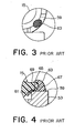
- Fig. 3 is a partially plan view illustrating the state of adhesive applied to the prior art lens holder;
- Fig. 4 is a fragmentary enlarged cross sectional view of the adhesively bonded portion of the prior art lens holder;
- Fig. 5 is a rear view of main portions of an optical pickup in accordance with an embodiment of the invention;
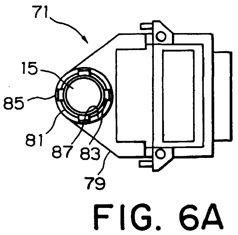
- Fig. 6A is a plan view of a lens holder shown in Fig. 5;
- Fig. 6B is a side elevation view of the optical pick up shown in Fig. 5, but in which the lens holder has been removed;
- Fig. 6C is a fragmentary enlarged cross section of a bonded portion of a lens shown in Fig. 6A;
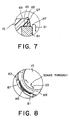
- Fig. 7 is a fragmentary cross sectional view illustrating the action of the lens holder shown in Fig. 6A; and
- Fig. 8 is a fragmentary plan view illustrating the action of the lens holder shown in Fig. 6A.
-
- Before describing the preferred embodiments of the present invention, a conventional pickup is described by referring to Figs. 1-4 to better understand the invention.
- Referring to Fig. 1, an
optical pickup 11 is used in an optical disk drive, such as a CD recorder. Thepickup 11 includes anoptical base 13, alens holder 17, adamper base 19, and anactuator base 21. Thelens holder 17 is equipped with anobjective lens 15, a tracking coil (not shown), and a focusing coil (not shown). Theactuator base 21 houses thelens holder 17 and thedamper base 19. - The
optical pickup 11 has alaser 23 acting as a light source for radiating a laser beam. The laser beam emitted from thelaser 23 is directed onto an optical disk (CD-R) disk that is an optical recording medium through a diffraction grating, a beam splitter, and a collimator lens (none of which are shown) and through theobjective lens 15. Light reflected from the optical disk hits a photodiode (not shown) that is a light-receiving device through theobjective lens 15, the collimator lens, and the beam splitter. That is, the photodiode receives the light reflected from the optical disk. - Optical parts including the
laser 23 and the beam splitter are held to theoptical base 13, which in turn is securely mounted to the enclosure (not shown) of the optical disk drive. A printed-circuit board 25 is mounted to a side surface of theoptical base 13. The printed-circuit board 25 is electrically connected with other electrical parts (not shown) of the optical disk drive via aflexible cable 27 connected with theboard 25. - The
lens holder 17 and thedamper base 19 are connected together byplural suspension wires 29, thus forming a subassembly accommodated in theactuator base 21. A part of theactuator base 21 forms ayoke 31 with which a magnet is combined. - The
actuator base 21 comprises a frame molded from a metallic material and has a damper base-receiving portion (not shown) at a side of one end of the frame to receive thedamper base 19. Asupport block 33 for locking thedamper base 19 is present in this receiving portion. Thesupport block 33 is molded integrally with theactuator base 21. Substantiallysemicircular protrusions 37 are formed on both sidewalls of the frame and are held bysupport portions 35 formed on theoptical base 13. - A
damper base cover 39 is molded from a transparent resinous material and is mounted to thedamper base 19, and has also a rear portion on which fixingportions 41 for anchoring respective one end of thesuspension wires 29 are mounted. A vibration-damping material (not shown) is injected in the space between thedamper base 19 and thedamper base cover 39 to damp vibrations of thesuspension wires 29. - A
flexible circuit 43 to be soldered to ends of thesuspension wires 29 that are located ahead of the fixed ends is mounted on the rear wall of thedamper base 19. Thedamper base 19 is inserted in the space among the sidewalls of theactuator base 21 and thesupport block 33 and made stationary. - The
support block 33 and thedamper base 19 are squeezed in between a screw (bolt) 45 and anut 47. Thedamper base 19 is rotatable about the screw to permit adjustment of the skew. - Before the
damper base 19 is fixedly mounted to theactuator base 21, thesuspension wires 29 are mounted to thedamper base 19. That is, thelens holder 17 and thedamper base 19 are assembled into a unit by theplural suspension wires 29. The resulting unit is received and mounted in theactuator base 21. - Referring to Figs. 2A, 2B, and 2C, the
lens holder 17 of the objective lens hasflat support portions seat portion 53 cylindrically protruding from thesupport portion 49, and the aforementionedobjective lens 15 installed on theseat portion 53. Theseat portion 53 is provided withcrisscross grooves 55 extending diametrically.Claws 57 protrude upward from thegrooves 55. - The
objective lens 15 of the optical pickup and thelens holder 17 holding the pickup are fastened together by placing theobjective lens 15 on a flat top-end surface 59 of theseat portion 53 of thelens holder 17 and using an adhesive such as a UV-curable resin, as best shown in Fig. 2C. The bottom end surface of the fringing portion of the objective lens, the outer side surface, and the top end surface of the fringing portion of the objective lens are indicated by 65, 67, and 69, respectively. - Referring next to Figs. 3 and 4, if a gap or recess is present in a part of the flat top-
end surface 59 of theseat portion 53 on which theobjective lens 15 is placed, adhesive 63 may soak through theobjective lens 15 toward its center as indicated by anarrow 61 in Fig. 4. If this adhesive reaches a portion of the objective lens 52 through which light can pass, (hereinafter referred to as the effective region of the objective lens) the optical characteristics of the pickup will deteriorate. - Now description will be made as regards the preferred embodiment of the present invention with reference to Figs. 5-8.
- Referring to Fig. 5, an optical pickup is equipped with a
lens holder 71, anactuator base 73, adamper base 75 connected to theactuator base 73, andsuspension wires 77. Anobjective lens 15 is mounted on thelens holder 71. - Referring next to Figs. 6A and 6B, the
lens holder 71 has asupport portion 79 at one end. Aseat portion 81 protrudes cylindrically from thesupport portion 79. Theseat portion 81 is formed withcrisscross grooves 83 extending diametrically.Claws 85 protrude upward from the top ends of thegrooves 83, and are used to place and lock the objective lens in position. - As best shown in Fig. 6C, the
seat portion 81 has a top-end surface 87 on which the periphery of theobjective lens 15 is placed. This top-end surface 87 is inclined mildly outwardly. - The action and advantages of this
lens holder 71 in accordance with one embodiment of the invention are next described by referring to Figs. 7 and 8. - Referring to Fig. 7, a surface of the
objective lens 15 used for adhesive bonding normally consists of the top-end surface 87 of theseat portion 81 of thelens holder 71 and theouter surface 67 of theobjective lens 15. A slight gap is created between thebottom surface 65 of the peripheral portion of theobjective lens 15 and the inclined top-end surface 87, whereby the bottom surface acts as an adhesive surface. By tilting the top-end surface 87 of theseat portion 81, an extra portion of adhesive 89 flows along the downwardly inclined surface of the top-end surface 87 toward the outer periphery of theobjective lens 15 as indicated by anarrow 91 without leaking toward the center of theobjective lens 15. - In the
lens holder 71 of the construction as described above, the applied adhesive 89 spreads over the whole gap between theobjective lens 15 and theseat portion 81 of thelens holder 71 by capillarity as indicated by thearrow 93 in Fig. 8. Consequently, the adhesive 89 permeates the whole outer surface of the objective lens, thus enhancing the adhesion. As a result, stronger surface adhesion is possible. - As described thus far, the present invention prevents
extra adhesive 89 on theseat portion 81 of theobjective lens 15 of thelens holder 71 from leaking toward the center of theobjective lens 15; otherwise, the effective range of theobjective lens 15 would be contaminated. Furthermore, the adhesive 89 permeates uniformly the gap between theobjective lens 15 and thelens holder 71. Hence, thelens holder 71 capable of stronger adhesive bonding and an optical pick up using this lens holder can be provided. - While the present invention has been described in its preferred embodiments, it is to be understood that the words which have been used are words of description rather than limitation, and changes may be made to the invention without departing from its scope as defined by the appended claims.
- Each feature disclosed in this specification (which term includes the claims) and/or shown in the drawings may be incorporated in the invention independently of other disclosed and/or illustrated features.
- The text of the abstract filed herewith is repeated here as part of the specification.
- A lens holder is capable of firmly holding the objective lens of an optical pickup to the holder without contamination of the effective range of the objective lens due to adhesive. An optical pickup using this lens holder is also disclosed. The lens holder 10 has a seat portion 3 for locking the objective lens 1 of the optical pickup. The seat portion 3 has a top-end surface 3a that is inclined and sinks outwardly.
Claims (6)
- An optical pick up having a lens holder on which an objective lens is held, said lens holder having a seat portion for locating said objective lens, said seat portion having a top surface (viewed with the lens axis vertical) which is inclined downwardly away from the lens.
- The optical pick up of claim 1, wherein adhesive fills between an outer surface of the objective lens and said inclined surface to lock said objective lens to said seat portion.
- The optical pick up of claim 2, wherein said adhesive consists essentially of a UV-curable resin.
- A lens holder having a seat portion for locking an objective lens of an optical pick up, said seat portion having a top surface that is inclined outwardly and downwardly.
- The lens holder of claim 4, wherein adhesive fills between an outer surface of said objective lens and said inclined surface to lock said objective lens to said seat portion.
- The lens holder of claim 5, wherein said adhesive consists essentially of a UV-curable resin.
Applications Claiming Priority (2)
| Application Number | Priority Date | Filing Date | Title |
|---|---|---|---|
| JP1827199 | 1999-01-27 | ||
| JP11018271A JP2000215489A (en) | 1999-01-27 | 1999-01-27 | Optical pickup device and lens holder used for it |
Publications (1)
| Publication Number | Publication Date |
|---|---|
| EP1024483A1 true EP1024483A1 (en) | 2000-08-02 |
Family
ID=11967000
Family Applications (1)
| Application Number | Title | Priority Date | Filing Date |
|---|---|---|---|
| EP00300618A Withdrawn EP1024483A1 (en) | 1999-01-27 | 2000-01-27 | Optical pickup and lens holder therefor |
Country Status (3)
| Country | Link |
|---|---|
| US (1) | US6342979B1 (en) |
| EP (1) | EP1024483A1 (en) |
| JP (1) | JP2000215489A (en) |
Cited By (1)
| Publication number | Priority date | Publication date | Assignee | Title |
|---|---|---|---|---|
| EP1426929A3 (en) * | 2002-11-08 | 2005-10-19 | Pioneer Corporation | Actuator for use in pickup device |
Families Citing this family (3)
| Publication number | Priority date | Publication date | Assignee | Title |
|---|---|---|---|---|
| JP2008000807A (en) * | 2006-06-26 | 2008-01-10 | Fujitsu Ltd | Mold for use in mold casting method, and method for manufacturing vibration damping member using the mold |
| EP3761099B1 (en) | 2018-04-28 | 2023-11-22 | Ningbo Sunny Opotech Co., Ltd. | Optical lens assembly, camera module, and assembling method therefor |
| CN112649933B (en) * | 2018-04-28 | 2023-06-09 | 宁波舜宇光电信息有限公司 | Optical lens, camera module and assembly method thereof |
Citations (3)
| Publication number | Priority date | Publication date | Assignee | Title |
|---|---|---|---|---|
| WO1995013904A1 (en) * | 1993-06-22 | 1995-05-26 | Abrams Herbert M | Lamination of composite eyeglass lenses |
| EP0736788A2 (en) * | 1995-04-07 | 1996-10-09 | Discovision Associates | Method and apparatus for aligning an objective lens |
| US5781351A (en) * | 1995-06-02 | 1998-07-14 | Matsushita Electric Industrial Co., Ltd. | Mounting structure of objective lens for optical pick-up used for optical disk device |
Family Cites Families (1)
| Publication number | Priority date | Publication date | Assignee | Title |
|---|---|---|---|---|
| US5553052A (en) * | 1993-03-02 | 1996-09-03 | Asahi Kogaku Kogyo Kabushiki Kaisha | Inclination of an objective lens in an optical information system |
-
1999
- 1999-01-27 JP JP11018271A patent/JP2000215489A/en not_active Withdrawn
-
2000
- 2000-01-26 US US09/491,819 patent/US6342979B1/en not_active Expired - Fee Related
- 2000-01-27 EP EP00300618A patent/EP1024483A1/en not_active Withdrawn
Patent Citations (3)
| Publication number | Priority date | Publication date | Assignee | Title |
|---|---|---|---|---|
| WO1995013904A1 (en) * | 1993-06-22 | 1995-05-26 | Abrams Herbert M | Lamination of composite eyeglass lenses |
| EP0736788A2 (en) * | 1995-04-07 | 1996-10-09 | Discovision Associates | Method and apparatus for aligning an objective lens |
| US5781351A (en) * | 1995-06-02 | 1998-07-14 | Matsushita Electric Industrial Co., Ltd. | Mounting structure of objective lens for optical pick-up used for optical disk device |
Cited By (2)
| Publication number | Priority date | Publication date | Assignee | Title |
|---|---|---|---|---|
| EP1426929A3 (en) * | 2002-11-08 | 2005-10-19 | Pioneer Corporation | Actuator for use in pickup device |
| US7286448B2 (en) | 2002-11-08 | 2007-10-23 | Pioneer Corporation | Actuator for use in pickup device in reducing lens distortion |
Also Published As
| Publication number | Publication date |
|---|---|
| US6342979B1 (en) | 2002-01-29 |
| JP2000215489A (en) | 2000-08-04 |
Similar Documents
| Publication | Publication Date | Title |
|---|---|---|
| US20030043728A1 (en) | Structure for connecting a lens to a lens holder without using an adhesive | |
| KR100296678B1 (en) | Objective lens drive device, optical pickup device using this objective lens drive device, and optical disc recording and playback device | |
| US6342979B1 (en) | Optical pickup and lens holder therefor | |
| US7246364B2 (en) | Optical pickup device | |
| JP2000252577A (en) | Laser beam emission unit | |
| US6246532B1 (en) | Optical pickup comprising a damper base having an oval hole | |
| US20060077780A1 (en) | Optical pickup unit and optical disc drive having the same | |
| US6324151B1 (en) | Part fixing method capable of costing down | |
| US20040095872A1 (en) | Optical pickup device and its manufacturing method | |
| JP3779608B2 (en) | Optical head device | |
| JP2000293873A (en) | Optical pickup | |
| JPH1139662A (en) | Optical pickup | |
| CN100338667C (en) | Laser pickup device | |
| JP2000249885A (en) | Beam shaping lens and positioning method thereof | |
| JP3518663B2 (en) | Optical pickup | |
| JP2000020982A (en) | Two-lens optical head device and disk recording or reproducing device | |
| US20060056080A1 (en) | Optical pickup unit comprising an optical pickup actuator wobblably held in an optical base | |
| JP2004296039A (en) | Optical pickup device | |
| KR20000007437U (en) | Objective lens assembly structure of optical pickup device | |
| JP2006031903A (en) | Optical pickup actuator | |
| JP2002197705A (en) | Optical head device and manufacturing method therefor | |
| JP2003217134A (en) | Optical pickup device | |
| US20060104166A1 (en) | Combination of lens and lens holder and optical pickup unit having the same | |
| JP2000215483A (en) | Optical pickup and method of assembling the same | |
| JPH04109439A (en) | Optical pickup |
Legal Events
| Date | Code | Title | Description |
|---|---|---|---|
| PUAI | Public reference made under article 153(3) epc to a published international application that has entered the european phase |
Free format text: ORIGINAL CODE: 0009012 |
|
| AK | Designated contracting states |
Kind code of ref document: A1 Designated state(s): DE FR GB NL |
|
| AX | Request for extension of the european patent |
Free format text: AL;LT;LV;MK;RO;SI |
|
| 17P | Request for examination filed |
Effective date: 20001205 |
|
| AKX | Designation fees paid |
Free format text: DE FR GB NL |
|
| STAA | Information on the status of an ep patent application or granted ep patent |
Free format text: STATUS: THE APPLICATION IS DEEMED TO BE WITHDRAWN |
|
| 18D | Application deemed to be withdrawn |
Effective date: 20040803 |