EP1024412A2 - Apparatus for driving squeegee roller for liquid electrophotographic printer - Google Patents
Apparatus for driving squeegee roller for liquid electrophotographic printer Download PDFInfo
- Publication number
- EP1024412A2 EP1024412A2 EP00300529A EP00300529A EP1024412A2 EP 1024412 A2 EP1024412 A2 EP 1024412A2 EP 00300529 A EP00300529 A EP 00300529A EP 00300529 A EP00300529 A EP 00300529A EP 1024412 A2 EP1024412 A2 EP 1024412A2
- Authority
- EP
- European Patent Office
- Prior art keywords
- squeegee roller
- photoreceptor belt
- squeegee
- driving
- gear
- Prior art date
- Legal status (The legal status is an assumption and is not a legal conclusion. Google has not performed a legal analysis and makes no representation as to the accuracy of the status listed.)
- Granted
Links
Images



Classifications
-
- B—PERFORMING OPERATIONS; TRANSPORTING
- B41—PRINTING; LINING MACHINES; TYPEWRITERS; STAMPS
- B41F—PRINTING MACHINES OR PRESSES
- B41F31/00—Inking arrangements or devices
- B41F31/30—Arrangements for tripping, lifting, adjusting, or removing inking rollers; Supports, bearings, or forks therefor
-
- G—PHYSICS
- G03—PHOTOGRAPHY; CINEMATOGRAPHY; ANALOGOUS TECHNIQUES USING WAVES OTHER THAN OPTICAL WAVES; ELECTROGRAPHY; HOLOGRAPHY
- G03G—ELECTROGRAPHY; ELECTROPHOTOGRAPHY; MAGNETOGRAPHY
- G03G15/00—Apparatus for electrographic processes using a charge pattern
- G03G15/06—Apparatus for electrographic processes using a charge pattern for developing
- G03G15/10—Apparatus for electrographic processes using a charge pattern for developing using a liquid developer
- G03G15/11—Removing excess liquid developer, e.g. by heat
Definitions
- the present invention relates to a liquid electrophotographic printer, and more particularly, to a squeegee roller driving apparatus for squeegeeing excess developer liquid from a transfer surface of a photosensitive medium.
- a liquid electrophotographic printer such as a colour laser printer includes a development device 20 for supplying a developer liquid to an electrostatic latent image formed on a transfer surface 10a of a photoreceptor belt 10 as a photosensitive medium to develop the electrostatic latent image.
- a developer liquid spray nozzle 21, a development roller 22 and a squeegee roller 23 are sequentially installed.
- the development roller 22 transfers a developer liquid to the transfer surface 10a of the photoreceptor belt 10.
- the squeegee roller 23 squeezes the developer liquid transferred on the transfer surface 10a of the photoreceptor belt 10.
- Reference numerals 12 and 13 denote backup rollers opposite to the development roller 22 and the squeegee roller 23 to apply tension to the photoreceptor belt 10.
- the development roller 22 and the squeegee roller 23, as shown in Figure 2, are installed in separate elevation apparatuses 32 and 33 to be controlled to elevate according to the operating mode of the printer.
- the elevation apparatuses 32 and 33 generally each includes a spring (not shown) configured to adjust its elastic force by a cam mechanism (not shown). In response to the adjusted elastic force of the spring, the development roller 22 and the squeegee roller 23 are lifted or lowered to be engaged in proximity of or disengaged from proximity of the photoreceptor belt 10.
- the development roller 22 and the squeegee roller 23 remain in a lifted state by the driving of the elevation apparatuses 32 and 33.
- the development roller 22 is lifted up to a location at which a gap of about 0.1 to 0.2 mm is formed between the photoreceptor belt 10 and the development roller 22.
- the squeegee roller 22 is lifted up to a location at which it presses the photoreceptor belt 10 with a force of approximately 20 kilograms even after it contacts the photoreceptor belt 10.
- the development roller 22 and the squeegee roller 23 are lowered to be completely disengaged from the photoreceptor belt 10.
- the developer liquid may accumulate and remain on a contact portion of the squeegee roller 23 and the photoreceptor belt 10.
- the excess developer liquid remaining on the photoreceptor belt 10 is referred to as a drip line (D).
- D The excess developer liquid remaining on the photoreceptor belt 10.
- Figure 2 illustrates the positional relationship between the photoreceptor belt 10, the development roller 22 and the squeegee roller 23 in a drip line removal mode, in which the development roller 22 is completely disengaged from the photoreceptor belt 10, as in the stop mode. Also, the squeegee roller 23 is controlled to rotate in reverse with respect to the rotating direction of the photoreceptor belt 10 in the printing mode, while the photoreceptor 10 remains pressed with a loading force of approximately 2 kilograms by adjusting the elastic force of the spring provided in the elevation apparatus 23.
- a conventional driving apparatus for rotating the squeegee roller 23 in reverse with respect to the traveling direction of the photoreceptor belt 10 includes a squeegee gear 24 installed at a shaft end of the squeegee roller 23, and a driving gear 25 installed at an output end of a driving source (M) positioned above the squeegee gear 24 to be engaged therewith.
- M driving source
- the squeegee roller 23 is configured to be capable of rotating in a forward or reverse direction, by installing a one-way bearing or clutch (not shown) on the driving shaft of the driving gear 25.
- the squeegee roller 23 contacts the photoreceptor belt 10 in the printing mode to rotate in the same direction as that of the photoreceptor belt 10 (in a forward direction) due to a frictional force therebetween.
- the squeegee gear 24 is subjected to the driving force applied from the driving gear 25 to rotate reversely.
- the squeegee roller 23 in the course of switching from a drip line removal mode, as shown in Figure 4A, to a stop mode, as shown in Figure 4B, the squeegee roller 23 is lowered so that the driving gear 25 and the squeegee gear 24 are spaced apart from each other, thereby stopping rotation.
- the drip line D is not completely removed due to the rolling trace of the squeegee roller 23, leaving a small amount of carrier (approximately 0.005 gram) on the transfer surface of the photoreceptor belt 10.
- the remaining carrier is transferred to an image (D') on printing paper 1, degrading the print quality of the printed image.
- an apparatus for driving a squeegee roller for a liquid electrophotographic printer which can enhance the accuracy in removing a drip line, by improving a driving mechanism such that the squeegee roller keeps rotating reversely for a while even when the squeegee roller is lowered in the course of switching from a drip line removal mode to a stop mode.
- an apparatus for driving a squeegee roller for a liquid electrophotographic printer having a squeegee roller installed to be capable of rotating in contact with a photoreceptor belt and to be lifted to and lowered from the photoreceptor belt, and driving means for rotating the squeegee roller in reverse with respect to the rotating direction of the photoreceptor belt
- the driving means comprises: a squeegee gear coaxially installed at one shaft end of the squeegee roller; a driving gear installed such that in a state where the squeegee roller contacts the photoreceptor belt, the centre of the rotation shaft thereof is positioned on a plane which is perpendicular to the elevating direction of the squeegee roller and which plane farther passes through the centre of the rotation shaft of the squeegee roller, to be engaged with the squeegee gear; and a driving source having an output shaft for rotating the driving gear to drive the sque
- the driving gear is positioned in the upper stream of the squeegee gear with respect to the traveling direction of the photoreceptor belt to be engaged therewith.
- the driving means is arranged for enabling rotation of the squeegee roller in a reverse direction to the rotating direction of the photoreceptor belt even when a drip line removal mode of the printer is terminated, such that the reverse rotation of the squeegee roller does not stop until the squeegee roller has completely disengaged from the photoreceptor belt.
- an apparatus for driving a squeegee roller for a liquid electrophotographic printer having a squeegee roller installed to be capable of rotating in contact with a photoreceptor belt and to be lifted to and lowered from the photoreceptor belt, and driving means for rotating the squeegee roller in reverse with respect to the rotating direction of the photoreceptor belt, wherein the driving means is arranged for enabling rotation of the squeegee roller in the reverse direction even when a drip line removal mode of the printer is being terminated, such that the reverse rotation of the squeegee roller does not stop until the squeegee roller has completely disengaged from the photoreceptor belt.
- said driving means preferably comprises: a squeegee gear coaxially installed at one shaft end of the squeegee roller; a driving gear installed such that in a state where the squeegee roller contacts the photoreceptor belt, the centre of the rotation shaft thereof is positioned on a plane which is perpendicular to the elevating direction of the squeegee roller and which plane further passes through the centre of the rotation shaft of the squeegee roller, to be engaged with the squeegee gear; and a driving source having an output shaft for rotating the driving gear to drive the squeegee roller to rotate in the reverse direction to the rotating direction of the photoreceptor belt.
- the driving gear is positioned upstream of the squeegee gear with respect of the travelling direction of the photoreceptor belt to be engaged therewith.
- an apparatus for driving a squeegee roller for a liquid electrophotographic printer includes a squeegee roller 230 installed to be lifted to and lowered from a photoreceptor belt 10 traveling along a circular track, a squeegee gear 240 installed at one shaft end thereof, a driving gear 250 engaged with the squeegee gear 230, and a driving source (M) having an output shaft for rotating the driving gear 250 to drive the squeegee roller 230 to rotate in a reverse direction to the rotating direction of the photoreceptor belt 10.
- M driving source
- the feature of the prevent invention lies in that in a state where the squeegee roller 230 contacts the photoreceptor belt 10, the driving gear 250 is installed such that the centre of the rotation shaft thereof is positioned on a plane perpendicular to the elevating direction of the squeegee roller 230 and passing through the centre of the rotation shaft of the squeegee roller 230, to be engaged with the squeegee roller 230.
- the driving gear 250 is preferably positioned in the upper stream of the squeegee gear 240.
- the squeegee roller 230 contacts the transfer surface of the photoreceptor belt 10 to rotate in the same direction as the photoreceptor belt 10 due to a frictional force therebetween. Also, the elevation of the squeegee roller 230 is controlled by a separate elevation apparatus (not shown) according to the operating mode of the printer. Although not shown, the elevation apparatus includes a spring and a cam mechanism for elevating the squeegee roller 230, as in the conventional apparatus.
- the squeegee roller 230 is configured to rotate in a forward or reverse direction such that a one-way bearing or clutch (not shown) is installed on the driving shaft of the driving gear 250.
- a one-way bearing or clutch (not shown) is installed on the driving shaft of the driving gear 250.
- the squeegee roller 230 contacts the photoreceptor belt 10 in the printing mode to rotate in the same direction as that of the photoreceptor belt 10 (in a forward direction) due to a frictional force therebetween.
- the squeegee gear 240 is subjected to the driving force applied from the driving gear 25 to rotate reversely.
- the driving gear 250 drives the squeegee gear 240 to rotate in a reverse direction to the rotating direction of the photoreceptor belt 10 in a printing mode.
- the squeegee roller 230 keeps pressing the photoreceptor belt 10 with a loading force of approximately 2 kilograms by adjusting the elastic force of the spring of the elevation apparatus (not shown), it rotates in a reverse direction to the rotating direction of the photoreceptor belt 10 in the printing mode.
- the carrier accommodating and remaining between the photoreceptor belt 10 and the squeegee roller 230 to form the drip line D is pushed back to be removed.
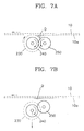
- the squeegee roller 230 is slowly lowered by the elevation apparatus (not shown) to begin disengaging from the photoreceptor belt 10, as shown in Figure 7B.
- the squeegee gear 240 is lowered while it keeps rotating in reverse, as shown in Figure 7C.
- the engagement between the squeegee gear 240 and the driving gear 250 is released, so that the squeegee roller 230 stops rotating.
- the squeegee roller 230 in contact with the transfer surface of the photoreceptor belt 10 does riot stop but keeps rotating in reverse until it has completely disengaged from the photoreceptor belt 10, thereby removing the drip line D as accurately as possible.
- a small amount of carrier approximately 0.002 gram or less
- the amount of carrier transferred to the printing paper 1 is minimized, thereby greatly improving the print quality of the ultimately printed image.
Landscapes
- Physics & Mathematics (AREA)
- General Physics & Mathematics (AREA)
- Wet Developing In Electrophotography (AREA)
- Electrostatic Charge, Transfer And Separation In Electrography (AREA)
- Discharging, Photosensitive Material Shape In Electrophotography (AREA)
- Electrophotography Configuration And Component (AREA)
Abstract
Description
Claims (6)
- An apparatus for driving a squeegee roller (230) for a liquid electrophotographic printer having a squeegee roller installed to be capable of rotating in contact with a photoreceptor belt (10) and to be lifted to and lowered from the photoreceptor belt (10), and driving means for rotating the squeegee roller (230) in reverse with respect to the rotating direction of the photoreceptor belt (10), wherein the driving means comprises:a squeegee gear (240) coaxially installed at one shaft end of the squeegee roller (230);a driving gear (250) installed such that in a state where the squeegee roller (230) contacts the photoreceptor belt (10), the centre of the rotation shaft thereof is positioned on a plane which is perpendicular to the elevating direction of the squeegee roller and which plane further passes through the centre of the rotation shaft of the squeegee roller (230), to be engaged with the squeegee gear (240); anda driving source (M) having an output shaft for rotating the driving gear (250) to drive the squeegee roller (230) to rotate in a reverse direction to the rotating direction of the photoreceptor belt (10).
- The driving apparatus according to claim 1, wherein the driving gear (250) is positioned in the upper stream of the squeegee gear (240) with respect to the traveling direction of the photoreceptor belt (10) to be engaged therewith.
- The driving apparatus of claim 1 or 2, wherein the driving means is arranged for enabling rotation of the squeegee roller (230) in a reverse direction to the rotating direction of the photoreceptor belt (10) even when a drip line removal mode of the printer is terminated, such that the reverse rotation of the squeegee roller (230) does not stop until the squeegee roller (230) has completely disengaged from the photoreceptor belt (10).
- An apparatus for driving a squeegee roller for a liquid electrophotographic printer having a squeegee roller (230) installed to be capable of rotating in contact with a photoreceptor belt (10) and to be lifted to and lowered from the photoreceptor belt (10), and driving means for rotating the squeegee roller (230) in reverse with respect to the rotating direction of the photoreceptor belt (10), wherein the driving means is arranged for enabling rotation of the squeegee roller (230) in the reverse direction even when a drip line removal mode of the printer is being terminated, such that the reverse rotation of the squeegee roller (230) does not stop until the squeegee roller (230) has completely disengaged from the photoreceptor belt (10).
- The driving apparatus of claim 4, wherein said driving means comprises:a squeegee gear (240) coaxially installed at one shaft end of the squeegee roller (230);a driving gear (250) installed such that in a state where the squeegee roller (230) contacts the photoreceptor belt (10), the centre of the rotation shaft thereof is positioned on a plane which is perpendicular to the elevating direction of the squeegee roller and which plane further passes through the centre of the rotation shaft of the squeegee roller (230), to be engaged with the squeegee gear (240); anda driving source (M) having an output shaft for rotating the driving gear (250) to drive the squeegee roller (230) to rotate in the reverse direction to the rotating direction of the photoreceptor belt (10).
- A driving apparatus according to claim 5, wherein the driving gear (250) is positioned upstream of the squeegee gear (240) with respect of the travelling direction of the photoreceptor belt (10) to be engaged therewith.
Applications Claiming Priority (2)
| Application Number | Priority Date | Filing Date | Title |
|---|---|---|---|
| KR10-1999-0002401A KR100524062B1 (en) | 1999-01-26 | 1999-01-26 | Apparatus for driving squeeze roller in a liquid printer |
| KR9902401 | 1999-01-26 |
Publications (3)
| Publication Number | Publication Date |
|---|---|
| EP1024412A2 true EP1024412A2 (en) | 2000-08-02 |
| EP1024412A3 EP1024412A3 (en) | 2001-07-04 |
| EP1024412B1 EP1024412B1 (en) | 2004-06-09 |
Family
ID=19572410
Family Applications (1)
| Application Number | Title | Priority Date | Filing Date |
|---|---|---|---|
| EP00300529A Expired - Lifetime EP1024412B1 (en) | 1999-01-26 | 2000-01-25 | Apparatus for driving squeegee roller for liquid electrophotographic printer |
Country Status (6)
| Country | Link |
|---|---|
| US (1) | US6198894B1 (en) |
| EP (1) | EP1024412B1 (en) |
| JP (1) | JP3286290B2 (en) |
| KR (1) | KR100524062B1 (en) |
| CN (1) | CN1123803C (en) |
| DE (1) | DE60011316T2 (en) |
Cited By (2)
| Publication number | Priority date | Publication date | Assignee | Title |
|---|---|---|---|---|
| KR100524062B1 (en) * | 1999-01-26 | 2005-10-26 | 삼성전자주식회사 | Apparatus for driving squeeze roller in a liquid printer |
| CN111149065A (en) * | 2017-11-29 | 2020-05-12 | 惠普发展公司,有限责任合伙企业 | Developing unit |
Families Citing this family (4)
| Publication number | Priority date | Publication date | Assignee | Title |
|---|---|---|---|---|
| JP3284111B2 (en) | 1999-06-30 | 2002-05-20 | 新潟富士ゼロックス製造株式会社 | Developing device for print output machine |
| JP2002108107A (en) * | 2000-09-27 | 2002-04-10 | Toshiba Corp | Image forming method and image forming apparatus |
| US7627310B2 (en) * | 2005-03-31 | 2009-12-01 | At&T Intellectual Property I, L. P. | Methods, systems, and products for distance-based discounting |
| US7877046B2 (en) * | 2007-12-07 | 2011-01-25 | Hewlett-Packard Development Company, L.P. | Hard imaging devices and hard imaging methods |
Family Cites Families (12)
| Publication number | Priority date | Publication date | Assignee | Title |
|---|---|---|---|---|
| US3955533A (en) * | 1972-09-27 | 1976-05-11 | Smith Ian E | Squeegee roller system for removing excess developer liquid from photoconductive surfaces |
| JPS5434541B2 (en) * | 1972-12-22 | 1979-10-27 | ||
| JPS5813908B2 (en) * | 1975-01-14 | 1983-03-16 | 株式会社リコー | Squeeze Roller Squeeze Roller |
| US4181094A (en) * | 1977-02-07 | 1980-01-01 | Savin Corporation | Excess developer removal apparatus |
| US4472128A (en) * | 1983-06-02 | 1984-09-18 | Sharp Die And Mold Co. | Quick change locator clamp assembly for plastic molding machine |
| JPH03286290A (en) * | 1990-03-30 | 1991-12-17 | Kubota Corp | Vending machine coin collection device |
| JPH0527653A (en) * | 1991-07-22 | 1993-02-05 | Brother Ind Ltd | Excess developer removing device |
| US5432591A (en) * | 1994-02-07 | 1995-07-11 | Hewlett-Packard Company | Multi-purpose foam roller in a liquid toner developer |
| JPH11512837A (en) * | 1995-09-29 | 1999-11-02 | ミネソタ・マイニング・アンド・マニュファクチャリング・カンパニー | Apparatus and method for removing developer from image forming support |
| KR19990063858A (en) * | 1995-09-29 | 1999-07-26 | 스프레이그 로버트 월터 | Apparatus and method for removing developer liquid from an image forming substrate |
| KR100524062B1 (en) * | 1999-01-26 | 2005-10-26 | 삼성전자주식회사 | Apparatus for driving squeeze roller in a liquid printer |
| KR101123803B1 (en) * | 2010-05-14 | 2012-03-12 | 주식회사 하이닉스반도체 | Stack package |
-
1999
- 1999-01-26 KR KR10-1999-0002401A patent/KR100524062B1/en not_active Expired - Fee Related
-
2000
- 2000-01-25 EP EP00300529A patent/EP1024412B1/en not_active Expired - Lifetime
- 2000-01-25 JP JP2000016221A patent/JP3286290B2/en not_active Expired - Fee Related
- 2000-01-25 DE DE60011316T patent/DE60011316T2/en not_active Expired - Fee Related
- 2000-01-26 CN CN00102882A patent/CN1123803C/en not_active Expired - Fee Related
- 2000-01-27 US US09/492,283 patent/US6198894B1/en not_active Expired - Lifetime
Cited By (4)
| Publication number | Priority date | Publication date | Assignee | Title |
|---|---|---|---|---|
| KR100524062B1 (en) * | 1999-01-26 | 2005-10-26 | 삼성전자주식회사 | Apparatus for driving squeeze roller in a liquid printer |
| CN111149065A (en) * | 2017-11-29 | 2020-05-12 | 惠普发展公司,有限责任合伙企业 | Developing unit |
| US10990037B2 (en) | 2017-11-29 | 2021-04-27 | Hewlett-Packard Development Company, L.P. | Developers |
| CN111149065B (en) * | 2017-11-29 | 2022-06-14 | 惠普发展公司,有限责任合伙企业 | developer |
Also Published As
| Publication number | Publication date |
|---|---|
| DE60011316D1 (en) | 2004-07-15 |
| KR20000051781A (en) | 2000-08-16 |
| EP1024412B1 (en) | 2004-06-09 |
| DE60011316T2 (en) | 2005-06-16 |
| EP1024412A3 (en) | 2001-07-04 |
| JP3286290B2 (en) | 2002-05-27 |
| KR100524062B1 (en) | 2005-10-26 |
| CN1123803C (en) | 2003-10-08 |
| CN1264064A (en) | 2000-08-23 |
| JP2000221793A (en) | 2000-08-11 |
| US6198894B1 (en) | 2001-03-06 |
Similar Documents
| Publication | Publication Date | Title |
|---|---|---|
| US7751750B2 (en) | Belt unit installed apparatus, image forming apparatus having the same, and method of installing/removing belt unit | |
| EP1024412A2 (en) | Apparatus for driving squeegee roller for liquid electrophotographic printer | |
| JPH11512836A (en) | Apparatus and method for removing developer from image forming support | |
| US7308220B2 (en) | Belt unit of electrophotographic printing apparatus | |
| US7315701B2 (en) | Systems and methods for reducing transfer deletions in an electrostatographic printer | |
| JPH06348148A (en) | Transfer device | |
| JP3911921B2 (en) | Continuous paper processing device and tractor | |
| JPH07134506A (en) | Image forming device | |
| US20070048034A1 (en) | Transfer assist blade dwell correction | |
| JP3094157B2 (en) | Color image forming equipment | |
| US20060110185A1 (en) | Imaging methods, imaging member charging methods, and image engines | |
| JP3524378B2 (en) | Image forming device | |
| EP0899628A2 (en) | Electrophotographic printer | |
| JP2575107Y2 (en) | Recording paper transport mechanism of printer using continuous recording paper | |
| JPH11231688A (en) | Image forming device | |
| JPH06342244A (en) | Image forming device | |
| KR100346697B1 (en) | Squeegee roll surpporting unit and ink cleaning method for liquid printer | |
| JPH11249448A (en) | Transfer device | |
| JP3891294B2 (en) | Image forming apparatus | |
| KR100213115B1 (en) | Wet type electrophotographic printer | |
| JP3770472B2 (en) | Electrophotographic equipment | |
| JP2626553B2 (en) | Electrophotographic developing device | |
| JP2001125452A (en) | Method for prolonging life of image drying device | |
| KR100234288B1 (en) | Carrier squeezing apparatus for printing device | |
| JP3704978B2 (en) | Image forming apparatus |
Legal Events
| Date | Code | Title | Description |
|---|---|---|---|
| PUAI | Public reference made under article 153(3) epc to a published international application that has entered the european phase |
Free format text: ORIGINAL CODE: 0009012 |
|
| 17P | Request for examination filed |
Effective date: 20000207 |
|
| AK | Designated contracting states |
Kind code of ref document: A2 Designated state(s): DE FR GB |
|
| AX | Request for extension of the european patent |
Free format text: AL;LT;LV;MK;RO;SI |
|
| PUAL | Search report despatched |
Free format text: ORIGINAL CODE: 0009013 |
|
| AK | Designated contracting states |
Kind code of ref document: A3 Designated state(s): AT BE CH CY DE DK ES FI FR GB GR IE IT LI LU MC NL PT SE |
|
| AX | Request for extension of the european patent |
Free format text: AL;LT;LV;MK;RO;SI |
|
| AKX | Designation fees paid |
Free format text: DE FR GB |
|
| 17Q | First examination report despatched |
Effective date: 20030523 |
|
| GRAP | Despatch of communication of intention to grant a patent |
Free format text: ORIGINAL CODE: EPIDOSNIGR1 |
|
| GRAS | Grant fee paid |
Free format text: ORIGINAL CODE: EPIDOSNIGR3 |
|
| GRAA | (expected) grant |
Free format text: ORIGINAL CODE: 0009210 |
|
| AK | Designated contracting states |
Kind code of ref document: B1 Designated state(s): DE FR GB |
|
| REG | Reference to a national code |
Ref country code: GB Ref legal event code: FG4D |
|
| REF | Corresponds to: |
Ref document number: 60011316 Country of ref document: DE Date of ref document: 20040715 Kind code of ref document: P |
|
| ET | Fr: translation filed | ||
| PLBE | No opposition filed within time limit |
Free format text: ORIGINAL CODE: 0009261 |
|
| STAA | Information on the status of an ep patent application or granted ep patent |
Free format text: STATUS: NO OPPOSITION FILED WITHIN TIME LIMIT |
|
| 26N | No opposition filed |
Effective date: 20050310 |
|
| PGFP | Annual fee paid to national office [announced via postgrant information from national office to epo] |
Ref country code: DE Payment date: 20090123 Year of fee payment: 10 |
|
| PGFP | Annual fee paid to national office [announced via postgrant information from national office to epo] |
Ref country code: GB Payment date: 20090121 Year of fee payment: 10 |
|
| PGFP | Annual fee paid to national office [announced via postgrant information from national office to epo] |
Ref country code: FR Payment date: 20090113 Year of fee payment: 10 |
|
| GBPC | Gb: european patent ceased through non-payment of renewal fee |
Effective date: 20100125 |
|
| REG | Reference to a national code |
Ref country code: FR Ref legal event code: ST Effective date: 20100930 |
|
| PG25 | Lapsed in a contracting state [announced via postgrant information from national office to epo] |
Ref country code: FR Free format text: LAPSE BECAUSE OF NON-PAYMENT OF DUE FEES Effective date: 20100201 |
|
| PG25 | Lapsed in a contracting state [announced via postgrant information from national office to epo] |
Ref country code: DE Free format text: LAPSE BECAUSE OF NON-PAYMENT OF DUE FEES Effective date: 20100803 |
|
| PG25 | Lapsed in a contracting state [announced via postgrant information from national office to epo] |
Ref country code: GB Free format text: LAPSE BECAUSE OF NON-PAYMENT OF DUE FEES Effective date: 20100125 |
|
| REG | Reference to a national code |
Ref country code: GB Ref legal event code: 732E Free format text: REGISTERED BETWEEN 20170406 AND 20170412 |
|
| REG | Reference to a national code |
Ref country code: FR Ref legal event code: TP Owner name: S-PRINTING SOLUTION CO., LTD., KR Effective date: 20170912 |