EP1024388A2 - Compact collimating apparatus - Google Patents
Compact collimating apparatus Download PDFInfo
- Publication number
- EP1024388A2 EP1024388A2 EP00300672A EP00300672A EP1024388A2 EP 1024388 A2 EP1024388 A2 EP 1024388A2 EP 00300672 A EP00300672 A EP 00300672A EP 00300672 A EP00300672 A EP 00300672A EP 1024388 A2 EP1024388 A2 EP 1024388A2
- Authority
- EP
- European Patent Office
- Prior art keywords
- polarization
- optical
- image
- sense
- light
- Prior art date
- Legal status (The legal status is an assumption and is not a legal conclusion. Google has not performed a legal analysis and makes no representation as to the accuracy of the status listed.)
- Withdrawn
Links
Images
Classifications
-
- G—PHYSICS
- G02—OPTICS
- G02B—OPTICAL ELEMENTS, SYSTEMS OR APPARATUS
- G02B27/00—Optical systems or apparatus not provided for by any of the groups G02B1/00 - G02B26/00, G02B30/00
- G02B27/28—Optical systems or apparatus not provided for by any of the groups G02B1/00 - G02B26/00, G02B30/00 for polarising
- G02B27/283—Optical systems or apparatus not provided for by any of the groups G02B1/00 - G02B26/00, G02B30/00 for polarising used for beam splitting or combining
-
- G—PHYSICS
- G02—OPTICS
- G02B—OPTICAL ELEMENTS, SYSTEMS OR APPARATUS
- G02B27/00—Optical systems or apparatus not provided for by any of the groups G02B1/00 - G02B26/00, G02B30/00
- G02B27/01—Head-up displays
- G02B27/017—Head mounted
- G02B27/0172—Head mounted characterised by optical features
-
- G—PHYSICS
- G02—OPTICS
- G02B—OPTICAL ELEMENTS, SYSTEMS OR APPARATUS
- G02B27/00—Optical systems or apparatus not provided for by any of the groups G02B1/00 - G02B26/00, G02B30/00
- G02B27/01—Head-up displays
- G02B27/017—Head mounted
- G02B27/0176—Head mounted characterised by mechanical features
-
- G—PHYSICS
- G02—OPTICS
- G02B—OPTICAL ELEMENTS, SYSTEMS OR APPARATUS
- G02B27/00—Optical systems or apparatus not provided for by any of the groups G02B1/00 - G02B26/00, G02B30/00
- G02B27/30—Collimators
-
- G—PHYSICS
- G02—OPTICS
- G02B—OPTICAL ELEMENTS, SYSTEMS OR APPARATUS
- G02B27/00—Optical systems or apparatus not provided for by any of the groups G02B1/00 - G02B26/00, G02B30/00
- G02B27/01—Head-up displays
- G02B27/0101—Head-up displays characterised by optical features
- G02B2027/0112—Head-up displays characterised by optical features comprising device for genereting colour display
- G02B2027/0116—Head-up displays characterised by optical features comprising device for genereting colour display comprising devices for correcting chromatic aberration
-
- G—PHYSICS
- G02—OPTICS
- G02B—OPTICAL ELEMENTS, SYSTEMS OR APPARATUS
- G02B27/00—Optical systems or apparatus not provided for by any of the groups G02B1/00 - G02B26/00, G02B30/00
- G02B27/01—Head-up displays
- G02B27/017—Head mounted
- G02B2027/0178—Eyeglass type
-
- G—PHYSICS
- G02—OPTICS
- G02B—OPTICAL ELEMENTS, SYSTEMS OR APPARATUS
- G02B5/00—Optical elements other than lenses
- G02B5/30—Polarising elements
Definitions
- the present invention relates generally to visual display systems and, more particularly, to a compact, collimating system utilizing a polarization selective optical element in combination with a quarter wave plate.
- U.S. Patent No. 4,704,010 discloses a device capable of generating an optical collimating beam using a single, piano-convex lens.
- a collimating mark is applied on the convex surface and a reflective coating is applied to the central portion of the plano surface.
- Light emanating from the collimating mark makes a double pass through the lens, exiting the plano surface as a collimated beam.
- the collimating mark is imaged at infinity.
- the collimating mark is illuminated using a prism.
- U.S. Patent No. 4,859,031 discloses an optical collimating device using a semi-reflective concave mirror and a cholesteric liquid crystal element.
- the collimator is used in conjunction with a combiner, thus allowing the system to be used in a heads-up display device.
- Images in the line of sight of the viewer substantially pass through the combiner, semi-reflective mirror, and cholesteric liquid crystal to the viewer.
- Images generated by a source are reflected by the combiner into the line of sight of the viewer.
- the generated images pass through the semi-reflective mirror to the cholesteric liquid crystal element.
- the cholesteric element reflects the images back to the concave side of the semi-reflective mirror.
- the concave mirror creates an image of the source at the same time it reverses the polarization of the image, thus allowing it to pass through the cholesteric element to the viewer.
- U.S. Patent No. 5,408,346 discloses an optical collimating device using a cholesteric liquid crystal element, the device exhibiting improved image transmissivity. Both reflective and transmissive systems are disclosed. The patent also discloses the use of the collimator in conjunction with a combiner, thus allowing multiple images to be superimposed for viewing by the user.
- U.S. Patent No. 5,715,023 discloses a compact display system that can be used as a collimating eyepiece.
- the system uses a cholesteric liquid crystal element in combination with an optical doublet.
- a partially reflective coating is at the interface between the two singlets which comprise the doublet.
- the design of this system reduces the number of element to air and/or element to element interfaces, thus reducing losses and ghosting while making a sturdy, vibration tolerant display system.
- multiple cholesteric liquid crystal elements are used, thus achieving a multicolor display system.
- the present invention provides a compact, lightweight display system which finds particular application as a collimating eyepiece.
- the system utilizes a polarization selective optical element, or PS element, that reflects one linear polarization state while transmitting radiation of the orthogonal linear polarization state.
- the PS element of the invention is used in combination with a quarter wave plate and an optical element, the optical element including a partially reflective surface.
- the optical element used in combination with the PS element is an optical doublet. In this configuration the partially reflective coating is at the interface between the two singlets that comprise the doublet.
- the system includes an image source that either alone, or in combination with other optical elements, produces circularly polarized light of the desired handedness.
- the image source may produce randomly polarized light that is then passed through a linear polarizer and a quarter wave retarder in order to achieve the desired circular polarization.
- the light from the source passes through the optical element, including the partially reflective coating, before passing through the quarter wave plate.
- the partially reflective coating does not alter the polarization of the transmitted light while the quarter wave plate causes the circularly polarized light to become linearly polarized.
- the system is designed such that the PS element will reflect the particular linear polarization of the light passing through the quarter wave plate.
- the light After reflection by the PS element, the light passes through the quarter wave plate a second time, thereby returning to the same handedness of circular polarization as originally emitted by the source. A portion of this light is reflected by the partially reflective coating on the optical element, this reflection causing the rotary sense of the circularly polarized light to become reversed. Due to this reversal, the light reflected by the optical element is allowed to pass virtually unheeded through the combination of the quarter wave plate and the PS element.
- the entire device is bonded together, thereby achieving an extremely vibration tolerant device.
- the source and any required source polarizers are bonded to an optical doublet, the doublet including the partially reflective coating at the interface between the singlets.
- the quarter wave plate and PS element combination are directly deposited onto the surface of the doublet opposite the source.
- another polarizer as well as an anti-reflection coating can be applied to the exit surface of the device.
- light from the image source is reflected off of a combiner into the device, thus allowing a second image to be combined with the first image.
- the combiner can utilize a simple partially reflective coating or a wavelength or polarization sensitive reflective coating. This embodiment of the invention is ideally suited for use with a heads-up display.
- the present invention utilizes a polarization selective optical element, hereafter referred to as a PS element, that reflects one liner polarization state while transmitting radiation of the orthogonal liner polarization state.
- a PS element polarization selective optical element
- An example of such a material is the Dual Brightness Enhancement Film (DBEF) produced by 3MTM.
- DBEF Dual Brightness Enhancement Film
- Such material can be designed to efficiently reflect electromagnetic radiation in a broad band of wavelengths, for example visible light, that is of a particular sense of plane, or linear, polarization while transmitting light of an orthogonal polarization.
- a PS element can be designed to reflect p-polarized visible light while transmitting s-polarized light. The PS element does not alter either the polarization of the transmitted light or the polarization of the reflected light.
- Fig. 1 is an illustration of an imaging system 100 according to the invention.
- This embodiment of the invention utilizes a PS element 101 in conjunction with a quarter wave plate 103.
- System 100 also includes a doublet comprised of two plano singlets, 105 and 107, cemented together and an image source 109.
- source 109 produces circularly polarized light.
- the curvature of the optical doublet of system 100 is designed to produce a collimated image from source 109, for example at a viewing location 111.
- the production of a collimated image is the preferred application of the invention, the system can also be used for other applications.
- the preferred embodiment of the invention uses an optical doublet although a single optical element can be used with the invention.
- the use of an optical doublet as illustrated in Fig. 1 reduces the number of element to air and/or element to element interfaces, thereby reducing losses and ghosting while making a sturdier, more vibration tolerant display system.
- singlet 105 is a piano-convex lens and singlet 107 is a plano-concave lens.
- Singlets 105 and 107 have the same radius of curvature.
- a partially reflective coating 113 is a dielectric coating with a transmittance of approximately 50 percent and a reflectance of approximately 50 percent in the wavelength range of interest.
- a portion of the light from source 109 will pass unheeded through coating 113.
- the amount of light passed is dependent upon the reflectivity of coating 113.
- the polarization of the light passing through coating 113 is unaltered.
- the circularly polarized light passing through coating 113 passes through quarter wave plate 103 causing the circularly polarized light to become linearly polarized.
- the system is designed such that PS element 101 reflects the particular polarization of the linearly polarized light passing through polarizer 103. As the light reflected by PS element 101 passes through quarter wave plate 103 again, the polarization is changed from linear polarization to circularly polarized light of the same handedness as the light produced by source 109.
- a portion of this light is reflected by coating 113, the amount reflected being dependent upon the reflectivity of coating 113.
- the polarization of the light reflected by coating 113 will be reversed, thus allowing it to pass virtually unheeded through the combination of PS element 101 and quarter wave plate 103.
- the image created at site 111 by the light passing through system 100 depends primarily upon the curvature of coated surface 113.
- surface 113 can be designed to form a collimated light beam.
- the light from source 109 is right circularly polarized (i.e. , RCP).
- RCP right circularly polarized
- surface 113 is coated with a 50/50 coating
- approximately 50 percent of the light from source 109 will pass through coating 113 to quarter wave plate 103.
- PS element 101 reflects the linearly polarized light back through quarter wave plate 103, resulting in RCP light impinging on reflective surface 113.
- 50 percent of the light impinging on surface 113 is lost. That portion of light reflected by surface 113 reverses handedness, thus becoming left circularly polarized (i.e.
- LCP linearly polarized light of a second polarization orthogonal to the first polarization. This light passes through 101. Thus approximately 25 percent of the source radiation will be passed by system 100. Collimating system 100 can be designed to work equally well with other polarizations.
- the embodiment illustrated in Fig. 1 does not contain any polarizers that are directly associated with source 109. Therefore if source 109 produces radiation other than that for which the combination of PS element 101 and quarter wave plate 103 have been designed, this radiation will not undergo the proper reflection by coating surface 113.
- PS element 101 and quarter wave plate 103 are designed to reflect incident RCP light as in the prior example, LCP light produced by source 109 will pass through system 100 without being reflected by surface 113.
- surface 113 is intended to produce a collimated image of source 109, the LCP light produced by the source will pass unheeded through the system and therefore not be collimated by reflective surface 113. As a result, the quality of the image displayed at site 111 will be reduced.
- Fig. 2 illustrates an embodiment of the invention that is functionally equivalent to the embodiment illustrated in Fig. 1.
- the system includes source 109, quarter wave plate 103, and PS element 101.
- the optical doublet comprised of elements 105 and 107 is replaced by a single optical element 201.
- Optical element 201 includes a reflective coating, preferably deposited on surface 203 although the coating can also be applied to surface 205.
- the coated surface has the appropriate curvature to impart the desired degree of collimation to the light reflected by the PS element/quarter wave plate combination.
- Systems 100 and 200 share the same capability for broad-band imaging, thus enabling them to be used as a compact, multi-color (i.e. , multi-wavelength) collimating system.
- a broad-band reflective coating is preferably used. Such coatings are well known by those of skill in the art and therefore will not be described in detail in this specification.
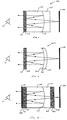
- Fig. 3 illustrates an alternate embodiment of the invention.
- This embodiment as in the embodiment illustrated in Fig. 1, is comprised of a plano-convex singlet 105, a plano-concave singlet 107, and a partially reflective coating 113 interposed between singlets 105 and 107. It is understood that the 105/107 doublet can be replaced with an element similar to element 201 of Fig. 2 while retaining the distinctive features of this embodiment.
- This embodiment also includes PS element 101 and quarter wave plate 103.
- This embodiment of the invention uses a source 301 that produces randomly polarized light.
- source 301 can be a cathode ray tube (CRT).
- the light from source 301 is linearly polarized with a polarizer 303 and then passed though a quarter wave retarder 305 which circularly polarizes the image light to the same rotary sense as that required by the PS element/quarter wave plate combination.
- an anti-reflection (AR) coating 307 is preferably applied to the outer surface of polarizer 303.
- This stack is comprised of a polarizer 309 and an AR coating 311.
- polarizer 303 and retarder 307 are coupled directly to source 301.
- Fig. 4 illustrates an alternate embodiment of the system shown in Fig. 3.
- source 301 is directly adhered to the device, thus eliminating another pair of air interfaces (i.e. , source/air and air/polarizer).
- the total system is comprised of source 301, linear polarizer 303, quarter wave retarder 305, plano-concave singlet 107, partial reflective coating 113, plano-convex singlet 105, quarter wave plate 103, PS element 101, polarizer 309 (optional), and AR coating 311 (optional).
- the only surface to air interface in this system is that at the exit plane, thus eliminating numerous sources of radiation loss and ghosting as well as improving image contrast and reducing the complexity and cost of the system.
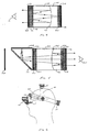
- Fig. 5 is an illustration of an embodiment of the present invention which allows an image from a first source to be combined with an image from a second source.
- the basic system in this embodiment is comprised of plano-convex singlet 501, plano-concave singlet 503, partial reflective coating 505 interposed between singlets 501 and 503, quarter wave plate 506, PS element 507, source 509, and combiner 511.
- the system also includes AR coating 513 (optional), liner polarizer 515, and quarter wave plate 517.
- Quarter wave plate 517 circularly polarizes the linearly polarized source light so that it has the appropriate rotary sense for the quarter wave plate 506/PS element 507 combination.
- the system also contains polarizer 519 and AR coating 521.
- combiner 511 can be a partial reflector which reflects the image from source 509 into the line of sight of an observer 525 while simultaneously passing the image of source 527 to the observer.
- Another type of combiner which can be used in this embodiment is a combiner which has a wavelength selective reflective coating.
- Such a combiner is ideally suited for applications in which only minimal information is required from source 509.
- source 509 may be used to project markings (e.g. , targeting system) or instrumentation (e.g. , fuel, air speed, altitude, etc. on a heads-up display) onto the image from source 527.
- combiner 511 can be designed to only reflect these one or two wavelengths while passing all other wavelengths of light.
- the advantage of this technique is that the reflective coating can be made very efficient, thus reflecting most of the radiation of the predetermined wavelengths from source 509 while passing all but a very small portion of the spectrum radiated by source 527.
- source 509 is an LCD
- the light emitted by source 509 is linearly polarized.
- combiner 511 is a polarizing beam splitter which is highly efficient in reflecting the polarized light emitted by source 509.
- source 527 emits unpolarized light
- approximately 50 percent of the light emitted by source 527 will be passed by combiner 511.
- linear polarizer 515 is not required.
- Fig. 6 illustrates the use of the invention in a headset configuration.
- the apparatus in this configuration includes a head mount 601 which attaches the apparatus to a user's head, and a display 603.
- display 603 is of the same design as shown in Fig. 5.
- Sizing knobs 605 adjust the size of the head mount to fit an individual user's head size.
- Display 603 is attached to head mount 601 via adjustable arms 607.
- the curvature of singlets 105 and 107 may be varied in order to impart different optical powers to the system.
- shape of the interface between singlets 105 and 107 may be spherical, aspheric, or plano.
- the reflective coating between the singlets need not be a 50/50 dielectric coating.
- a singlet can be used instead of the doublet as previously noted.
Landscapes
- Physics & Mathematics (AREA)
- General Physics & Mathematics (AREA)
- Optics & Photonics (AREA)
- Polarising Elements (AREA)
- Lenses (AREA)
Abstract
Description
Claims (18)
- An optical collimating apparatus for focussing an image at infinity or at a desired finite distance as viewed by an observer, the apparatus comprising:an optical element;a partially reflective coating deposited on a surface of said optical element;an image source for producing said image with light of at least a first rotary sense of circular polarization, said image source proximate to a first side of said optical element;a quarter wave plate proximate to a second side of said optical element, said quarter wave plate altering said first rotary sense of circular polarization to a first linear sense of polarization; anda polarization selective optical element proximate to said quarter wave plate, said polarization selective optical element substantially reflecting light of said first liner sense of polarization without altering said first linear sense of polarization, and said polarization selective optical element substantially transmitting light of a second linear sense of polarization, wherein said second linear sense of polarization is orthogonal to said first linear sense of polarization.
- The apparatus of claim 1, wherein said surface of said optical element is concave.
- The apparatus of claim 1 or 2, wherein said surface of said optical element is equivalent to said first side of said optical element.
- The apparatus of claim 1 or 2, wherein said surface of said optical element is equivalent to said second side of said optical element.
- The apparatus of claim 1, said optical element comprising:a first optical singlet having a first surface and a second surface; anda second optical singlet having a first surface and a second surface, said first surface of said first optical singlet coupled to said first surface of said second optical singlet, wherein said partially reflective coating is interposed between said first surface of said first optical singlet and said first surface of said second optical singlet.
- The apparatus of claim 5, wherein said first surface of said first optical singlet is concave, said second surface of said first optical singlet is plano, said first surface of said second optical singlet is convex, and said second surface of said second optical singlet is plano.
- The apparatus of any one of the preceding claims, wherein said image source is comprised of a liquid crystal display transmitting linearly polarized light and a circular polarizer for converting said linearly polarized light to at least said first rotary sense of circular polarization.,
- The apparatus of any one of claims 1 to 6, wherein said image source is comprised of a liquid crystal display transmitting linearly polarized light and a quarter wave retarder element for converting said linearly polarized light to at least said first rotary sense of circular polarization.
- The apparatus of any one of claims 1 to 6, wherein said image source is comprised of a simple source, a linear polarizing element, and a circular polarizer for converting linearly polarized light to at least said first rotary sense of circular polarization.
- The apparatus of any one of claims 1 to 6, wherein said image source is comprised of a simple source, a linear polarizing element, and a quarter wave retarder element for converting linearly polarized light to at least said first rotary sense of circular polarization.
- The apparatus of any one of the preceding claims, further comprising a polarizing element bonded to an exit surface of said polarization selective optical element.
- The apparatus of claim 11, further comprising an anti-reflection coating bonded to an exit surface of said polarizing element.
- The apparatus of any one of the preceding claims, further comprising a combiner element to combine said image with a second image produced by a second image source, said second image source in the line-of-sight of the observer, said combiner element interposed between said second image source and said first side of said optical element.
- The apparatus of claim 5, further comprising a combiner element to combine said image with a second image produced by a second image source, said second image source in the line-of-sight of the observer, said combiner element interposed between said second image source and said second surface of said first optical singlet.
- An optical apparatus for combining a first image and a second image, the apparatus comprising:a first optical singlet having a first surface and a second surface;a second optical singlet having a first surface and a second surface, said first surface of said first optical singlet coupled to said first surface of said second optical singlet;a partially reflective coating interposed between said first surface of said first optical singlet and said first surface of said second optical singlet;a LCD image source producing said first image with linearly polarized light of a first linear polarization within at least a first wavelength band;a polarizing beam splitter interposed between said LCD image source and said second surface of said first optical singlet, wherein a portion of said light of said first linear polarization and within said first wavelength band from said LCD image source is reflected by said polarizing beam splitter toward said first optical singlet;a second image source producing said second image, wherein a portion of said light from said second image source is transmitted by said polarizing beam splitter toward said first optical singlet;a circular polarizer proximate to said second surface of said first optical singlet, wherein said circular polarizer converts light of said first linear polarization to light of said first rotary sense of circular polarization;a quarter wave plate proximate to said second surface of said second optical singlet, said quarter wave plate altering said first rotary sense of circular polarization to a first linear sense of polarization; anda polarization selective optical element proximate to said quarter wave plate, said polarization selective optical element substantially reflecting light of said first linear sense of polarization without altering said first linear sense of polarization, and said polarization selective optical element substantially transmitting light of a second linear sense of polarization, wherein said second linear sense of polarization is orthogonal to said first linear sense of polarization.
- An optical collimating apparatus for focussing an image at infinity or at a desired finite distance as viewed by an observer, the apparatus comprising:a first optical singlet having a first surface and a second surface; anda second optical singlet having a first surface and a second surface, said first surface of said first optical singlet coupled to said first surface of said second optical singlet;a partially reflective coating interposed between said first surface of said first optical singlet and said first surface of said second optical singlet;an image source for generating said image, said image source coupled to said second surface of said first optical singlet;a linear polarizer interposed between said image source and said first optical singlet;a circular polarizer interposed between said linear polarizer and said first optical singlet, wherein at least a portion of light generated by said image source and passing through said linear polarizer and said circular polarizer has a first rotary sense of circular polarization;a quarter wave plate coupled to said second surface of said second optical singlet, said quarter wave plate altering said first rotary sense of circular polarization to a first linear sense of polarization; anda polarization selective optical element proximate to said quarter wave plate, said polarization selective optical element substantially reflecting light of said first linear sense of polarization without altering said first linear sense of polarization, and said polarization selective optical element substantially transmitting light of a second linear sense of polarization, wherein said second linear sense of polarization is orthogonal to said first liner sense of polarization.
- A method for optically collimating an image at infinity or at a desired finite distance from an observer, comprising the steps of:directing an image light having components within at least a first rotary sense of circular polarization at a first side of an optical element, said optical element including a partially reflective coating;converting said image light passing through said optical element from said first rotary sense of circular polarization to a first linear sense of polarization with a first quarter wave plate;reflecting said passed image light of said first linear sense of polarization with a polarization selective optical element, said reflected image light directed at a second side of said optical element;collimating a portion of said reflected image light with said partially reflective coating, said first rotary sense of circular polarization changing to a second rotary sense of circular polarization upon reflection by said partially reflective coating;converting said collimated image light of said second rotary sense of circular polarization to a second linear sense of polarization with said first quarter wave plate; andprojecting said collimated image light of said second linear sense of polarization through said polarization selective optical element to said observer.
- The method of claim 17, further comprising the steps of:generating said image light with an image source; andpassing said image light through a linear polarizing element and a second quarter wave plate for creating image light having components within at least said first rotary sense of circular polarization.
Applications Claiming Priority (2)
| Application Number | Priority Date | Filing Date | Title |
|---|---|---|---|
| US239356 | 1999-01-28 | ||
| US09/239,356 US6075651A (en) | 1999-01-28 | 1999-01-28 | Compact collimating apparatus |
Publications (2)
| Publication Number | Publication Date |
|---|---|
| EP1024388A2 true EP1024388A2 (en) | 2000-08-02 |
| EP1024388A3 EP1024388A3 (en) | 2003-03-12 |
Family
ID=22901815
Family Applications (1)
| Application Number | Title | Priority Date | Filing Date |
|---|---|---|---|
| EP00300672A Withdrawn EP1024388A3 (en) | 1999-01-28 | 2000-01-28 | Compact collimating apparatus |
Country Status (5)
| Country | Link |
|---|---|
| US (1) | US6075651A (en) |
| EP (1) | EP1024388A3 (en) |
| JP (1) | JP2000275566A (en) |
| AU (1) | AU2603800A (en) |
| WO (1) | WO2000045212A1 (en) |
Cited By (7)
| Publication number | Priority date | Publication date | Assignee | Title |
|---|---|---|---|---|
| EP1357417A3 (en) * | 2002-04-24 | 2005-02-02 | Seos Limited | An eyepiece for viewing a flat image |
| EP1653268A3 (en) * | 2004-10-27 | 2006-10-18 | CARL ZEISS JENA GmbH | Chromatic aberration reducing optical system, in particular for a microscope |
| WO2014094581A1 (en) * | 2012-12-17 | 2014-06-26 | 北京联想软件有限公司 | Display device and wearable glasses |
| WO2017136448A1 (en) | 2016-02-01 | 2017-08-10 | Kopin Corporation | Embedded reflective eyepiece |
| US9977246B2 (en) | 2014-03-18 | 2018-05-22 | 3M Innovative Properties Company | Low profile image combiner for near-eye displays |
| EP3410173A4 (en) * | 2016-01-28 | 2019-09-18 | Shenzhen Dlodlo New Technology Co., Ltd. | SHORT DISTANCE OPTICAL AMPLIFICATION MODULE, AMPLIFICATION METHOD AND AMPLIFICATION SYSTEM |
| EP3754409A4 (en) * | 2018-02-12 | 2021-04-14 | Matrixed Reality Technology Co., Ltd. | AUGMENTED REALITY DEVICE AND OPTICAL SYSTEM USED IN IT |
Families Citing this family (66)
| Publication number | Priority date | Publication date | Assignee | Title |
|---|---|---|---|---|
| JP2003529795A (en) | 2000-03-31 | 2003-10-07 | コーニンクレッカ フィリップス エレクトロニクス エヌ ヴィ | Head mounted display |
| JP4419281B2 (en) * | 2000-06-13 | 2010-02-24 | コニカミノルタホールディングス株式会社 | Eyepiece optics |
| GB0016326D0 (en) * | 2000-07-03 | 2000-08-23 | Seos Displays Ltd | A display device for mobile telecommunications apparatus |
| US6563638B2 (en) | 2001-04-26 | 2003-05-13 | Raytheon Company | Wide-angle collimating optical device |
| FR2834078B1 (en) * | 2001-12-21 | 2004-03-12 | Voxel Electronics Ind | OPTICAL DEVICE FOR VIEWING REAL IMAGES, OF HIGH BRIGHTNESS AND OF HIGH CONTRAST, AND HAVING A REDUCED SIZE IN DEPTH |
| FR2838529B1 (en) * | 2002-04-16 | 2004-06-18 | Essilor Int | THIN FILM POLARIZATION SEPARATOR, METHOD FOR MANUFACTURING SAME, AND OPHTHALMIC LENS HAVING PROJECTION INSERTS CONTAINING THE SAME |
| FR2847988B1 (en) * | 2002-12-03 | 2005-02-25 | Essilor Int | POLARIZATION SEPARATOR, PROCESS FOR MANUFACTURING THE SAME, AND OPHTHALMIC LENS HAVING PROJECTION INSERTS CONTAINING THE SAME |
| JP2005148655A (en) * | 2003-11-19 | 2005-06-09 | Sony Corp | Image display device |
| GB2437553A (en) | 2006-04-28 | 2007-10-31 | Sharp Kk | Optical system with two spaced apart partial reflectors for display |
| US20070273970A1 (en) * | 2006-05-26 | 2007-11-29 | Creative Display Systems, Llc | Wide field of view, compact collimating apparatus |
| WO2008108389A1 (en) * | 2007-03-07 | 2008-09-12 | Nec Corporation | Image display |
| GB2449682A (en) * | 2007-06-01 | 2008-12-03 | Sharp Kk | Optical system for converting a flat image to a non-flat image |
| GB2465786A (en) * | 2008-11-28 | 2010-06-02 | Sharp Kk | An optical system for varying the perceived shape of a display surface |
| JP4727737B2 (en) * | 2009-02-24 | 2011-07-20 | 三菱重工業株式会社 | Radiotherapy apparatus control apparatus and target part position measurement method |
| TWI455838B (en) * | 2012-07-27 | 2014-10-11 | Tyc Brother Ind Co Ltd | Composite reflection and refraction multiple imaging device for vehicle |
| US8982472B2 (en) | 2013-05-21 | 2015-03-17 | Matvey Lvovskiy | Method of widening of angular field of view of collimating optical systems |
| WO2015092867A1 (en) * | 2013-12-17 | 2015-06-25 | パイオニア株式会社 | Virtual-image generation element and heads-up display |
| KR20160143749A (en) | 2014-04-09 | 2016-12-14 | 쓰리엠 이노베이티브 프로퍼티즈 컴파니 | Head mounted display and low conspicuity pupil illuminator |
| JP6759212B2 (en) | 2014-12-31 | 2020-09-23 | スリーエム イノベイティブ プロパティズ カンパニー | Small projection system and related components |
| CN105093555B (en) | 2015-07-13 | 2018-08-14 | 深圳多新哆技术有限责任公司 | Short distance optical amplifier module and the nearly eye display optics module for using it |
| KR101689035B1 (en) * | 2015-07-17 | 2016-12-23 | 엘지전자 주식회사 | Display Device |
| US9557568B1 (en) | 2015-09-03 | 2017-01-31 | 3M Innovative Properties Company | Head-mounted display |
| KR102083468B1 (en) * | 2016-01-28 | 2020-03-02 | 쉔젠 들로들로 뉴 테크놀로지 컴퍼니 리미티드 | Near-field optical amplification module, near-field optical amplification method, and near-field optical amplification system |
| KR102257641B1 (en) * | 2016-03-21 | 2021-06-01 | 쉔젠 들로들로 뉴 테크놀로지 컴퍼니 리미티드 | Near field optical amplification module, glasses, helmet and virtual reality system |
| FI3249446T3 (en) * | 2016-03-21 | 2024-11-19 | Shenzhen Dlodlo New Tech Co Ltd | Short-distance optical magnification module, glasses, helmet and vr system |
| US10324292B2 (en) | 2016-03-21 | 2019-06-18 | Shenzhen Dlodlo New Technology Co., Ltd. | Short range optical amplification module, spectacles, helmet and VR system |
| US10197802B2 (en) * | 2016-07-29 | 2019-02-05 | Intevac, Inc. | Biocular compact collimation apparatus |
| CN110268301B (en) * | 2016-08-02 | 2022-04-01 | 苹果公司 | Optical system for head-mounted display |
| US10203489B2 (en) | 2016-08-02 | 2019-02-12 | Apple Inc. | Optical system for head-mounted display |
| KR20190073425A (en) | 2016-11-15 | 2019-06-26 | 쓰리엠 이노베이티브 프로퍼티즈 컴파니 | Optical lens and glasses containing it |
| KR102723417B1 (en) | 2016-12-26 | 2024-10-28 | 엘지디스플레이 주식회사 | Head mounted display |
| WO2018163035A1 (en) | 2017-03-08 | 2018-09-13 | 3M Innovative Properties Company | Optical system |
| US11543669B2 (en) | 2017-03-08 | 2023-01-03 | Meta Platforms Technologies, Llc | Wide angle variable neutral density filter |
| CN107024773B (en) * | 2017-06-02 | 2023-12-19 | 北京耐德佳显示技术有限公司 | Light and thin virtual image imaging device |
| US20190018255A1 (en) * | 2017-07-11 | 2019-01-17 | Google Llc | Compact near-eye optical system including a refractive beam-splitting convex lens |
| CN111108428A (en) | 2017-07-17 | 2020-05-05 | 加里夏普创新有限责任公司 | Wide Angle Compensation for Single Axis Retarder Stacks |
| US20190025602A1 (en) * | 2017-07-20 | 2019-01-24 | Google Llc | Compact near-eye display optics for augmented reality |
| CN111344613B (en) * | 2017-10-09 | 2022-09-27 | 3M创新有限公司 | Optical component and optical system |
| CN110007461A (en) * | 2017-12-30 | 2019-07-12 | 深圳多哚新技术有限责任公司 | Optical system |
| WO2018150773A1 (en) | 2018-01-12 | 2018-08-23 | カラーリンク・ジャパン 株式会社 | Optical device |
| US11249355B2 (en) | 2018-01-29 | 2022-02-15 | Gary Sharp Innovations, Llc | Color switch for reduced color cross-talk |
| US11269123B2 (en) * | 2018-01-29 | 2022-03-08 | Gary Sharp Innovations, Llc | Hollow triple-pass optical elements |
| JP7077656B2 (en) * | 2018-02-26 | 2022-05-31 | セイコーエプソン株式会社 | Virtual image display device |
| WO2019169170A1 (en) | 2018-03-02 | 2019-09-06 | Sharp Gary D | Retarder stack pairs for polarization basis vector transformations |
| JP2020024246A (en) * | 2018-08-06 | 2020-02-13 | セイコーエプソン株式会社 | Virtual image display device and magnifying optical system |
| JP7151255B2 (en) * | 2018-08-06 | 2022-10-12 | セイコーエプソン株式会社 | virtual image display |
| US10816804B2 (en) * | 2018-08-31 | 2020-10-27 | Google Llc | Near-eye display system with polarization-based optical path folding and variable focus catadioptric lens assembly |
| US11885959B1 (en) * | 2018-08-31 | 2024-01-30 | Apple Inc. | Optical system with ghost image mitigation |
| US10976552B2 (en) * | 2018-10-12 | 2021-04-13 | Google Llc | Near-eye system having polarization waveguide |
| EP3874303A4 (en) | 2018-11-02 | 2022-12-28 | Gary Sharp Innovations, Inc. | COMPACT POLARIZATION-BASED MULTIPASS OPTICAL ARCHITECTURES |
| US11002970B2 (en) * | 2019-02-06 | 2021-05-11 | Google Llc | Multi-focal catadioptric head mounted display with LC switch |
| US11586024B1 (en) | 2019-08-05 | 2023-02-21 | Meta Platforms Technologies, Llc | Peripheral see-through pancake lens assembly and display device with same |
| US11579425B1 (en) * | 2019-08-05 | 2023-02-14 | Meta Platforms Technologies, Llc | Narrow-band peripheral see-through pancake lens assembly and display device with same |
| US11391948B2 (en) | 2019-09-10 | 2022-07-19 | Facebook Technologies, Llc | Display illumination using a grating |
| US11467332B2 (en) | 2019-09-10 | 2022-10-11 | Meta Platforms Technologies, Llc | Display with switchable retarder array |
| US11726336B2 (en) | 2019-09-10 | 2023-08-15 | Meta Platforms Technologies, Llc | Active zonal display illumination using a chopped lightguide |
| US11422375B2 (en) | 2019-09-17 | 2022-08-23 | Meta Platforms Technologies, Llc | Curved see-through pancake lens assembly and display device including the same |
| CN110989172B (en) * | 2019-12-24 | 2021-08-06 | 平行现实(杭州)科技有限公司 | Waveguide display device with ultra-large field angle |
| KR102844854B1 (en) * | 2020-06-30 | 2025-08-11 | 구글 엘엘씨 | Free-form polarizing light guide |
| JP7580975B2 (en) * | 2020-08-28 | 2024-11-12 | キヤノン株式会社 | Observation equipment |
| CN111929906B (en) * | 2020-09-25 | 2021-01-22 | 歌尔光学科技有限公司 | Image display structure and head-mounted display device |
| JPWO2022176758A1 (en) * | 2021-02-22 | 2022-08-25 | ||
| JP7735138B2 (en) * | 2021-09-21 | 2025-09-08 | キヤノン株式会社 | Optical device and image display device |
| KR20250051860A (en) * | 2023-10-10 | 2025-04-18 | 삼성디스플레이 주식회사 | Lens assembly and display device comprising lens assembly |
| WO2025143899A1 (en) * | 2023-12-28 | 2025-07-03 | 삼성전자 주식회사 | Wearable electronic device including lens assembly |
| WO2025221021A1 (en) * | 2024-04-15 | 2025-10-23 | 삼성전자 주식회사 | Wearable electronic device comprising lens assembly |
Family Cites Families (25)
| Publication number | Priority date | Publication date | Assignee | Title |
|---|---|---|---|---|
| US3443858A (en) * | 1966-02-23 | 1969-05-13 | Farrand Optical Co Inc | Infinite optical image-forming apparatus |
| US3816005A (en) * | 1970-06-22 | 1974-06-11 | Sundstrand Data Control | Head-up display |
| US3679290A (en) * | 1971-01-06 | 1972-07-25 | Xerox Corp | Liquid crystal optical filter system |
| US3711181A (en) * | 1971-03-05 | 1973-01-16 | Xerox Corp | Optical notch filter |
| US3957348A (en) * | 1975-03-26 | 1976-05-18 | Xerox Corporation | Method for altering elliptically polarized light |
| US4390276A (en) * | 1980-05-14 | 1983-06-28 | Ring Sights Limited | Collimator gunsight |
| ATE22999T1 (en) * | 1983-05-07 | 1986-11-15 | Zeiss Carl Fa | DEVICE FOR GENERATING AN OPTICAL AIMING BEAM. |
| US4653875A (en) * | 1984-11-02 | 1987-03-31 | Hines Stephen P | Infinity display apparatus using cylindrical beam-splitters |
| US4781426A (en) * | 1986-09-30 | 1988-11-01 | Itt Defense Communications, A Division Of Itt Corporation | Optical fiber collimator/switch including liquid crystal polarizing material |
| DE3720375A1 (en) * | 1987-06-19 | 1988-12-29 | Fraunhofer Ges Forschung | PROJECTION DEVICE |
| US4859031A (en) * | 1987-08-03 | 1989-08-22 | Kaiser Electronics | Optical collimating apparatus |
| US5050966A (en) * | 1988-07-06 | 1991-09-24 | Kaiser Aerospace & Electronics Corporation | Optical combiner collimating apparatus |
| FR2660448B1 (en) * | 1990-04-03 | 1992-06-05 | Thomson Csf | DEVICE FOR PROJECTING IMAGES. |
| US5371617A (en) * | 1991-10-15 | 1994-12-06 | Canon Kabushiki Kaisha | Liquid crystal projector with one modulator including a member for preventing light from another modulator from entering the one |
| JPH0579530U (en) * | 1992-03-24 | 1993-10-29 | 日本ビクター株式会社 | Display system optics |
| US5267063A (en) * | 1992-07-02 | 1993-11-30 | At&T Bell Laboratories | Gradient index mirror for providing a collimated beam for liquid crystal displays and the like |
| JP3260867B2 (en) * | 1992-12-10 | 2002-02-25 | オリンパス光学工業株式会社 | Head-mounted display |
| US5325218A (en) * | 1992-12-31 | 1994-06-28 | Minnesota Mining And Manufacturing Company | Cholesteric polarizer for liquid crystal display and overhead projector |
| US5408346A (en) * | 1993-10-20 | 1995-04-18 | Kaiser Electro-Optics, Inc. | Optical collimating device employing cholesteric liquid crystal and a non-transmissive reflector |
| US5585946A (en) * | 1994-08-19 | 1996-12-17 | Vivitek Co., Ltd. | Virtual image display system with reduced ambient reflection and low radiation |
| JP3441188B2 (en) * | 1994-10-07 | 2003-08-25 | オリンパス光学工業株式会社 | Optical system and visual display device |
| US5596451A (en) * | 1995-01-30 | 1997-01-21 | Displaytech, Inc. | Miniature image generator including optics arrangement |
| JP3411953B2 (en) * | 1996-04-24 | 2003-06-03 | シャープ株式会社 | Optical device and head-mounted display using the optical device |
| US5715023A (en) * | 1996-04-30 | 1998-02-03 | Kaiser Electro-Optics, Inc. | Plane parallel optical collimating device employing a cholesteric liquid crystal |
| US6271969B1 (en) * | 1998-12-11 | 2001-08-07 | Agilent Technolgoies, Inc. | Folded optical system having improved image isolation |
-
1999
- 1999-01-28 US US09/239,356 patent/US6075651A/en not_active Expired - Fee Related
-
2000
- 2000-01-10 AU AU26038/00A patent/AU2603800A/en not_active Abandoned
- 2000-01-10 WO PCT/US2000/000450 patent/WO2000045212A1/en not_active Ceased
- 2000-01-26 JP JP2000056523A patent/JP2000275566A/en active Pending
- 2000-01-28 EP EP00300672A patent/EP1024388A3/en not_active Withdrawn
Cited By (17)
| Publication number | Priority date | Publication date | Assignee | Title |
|---|---|---|---|---|
| EP1357417A3 (en) * | 2002-04-24 | 2005-02-02 | Seos Limited | An eyepiece for viewing a flat image |
| EP1653268A3 (en) * | 2004-10-27 | 2006-10-18 | CARL ZEISS JENA GmbH | Chromatic aberration reducing optical system, in particular for a microscope |
| EP1892551A3 (en) * | 2004-10-27 | 2010-02-03 | Carl-Zeiss Jena GmbH | Chromatic aberration reducing optical system |
| WO2014094581A1 (en) * | 2012-12-17 | 2014-06-26 | 北京联想软件有限公司 | Display device and wearable glasses |
| US9612448B2 (en) | 2012-12-17 | 2017-04-04 | Beijing Lenovo Software Ltd. | Display device and wearable glasses |
| US10345598B2 (en) | 2014-03-18 | 2019-07-09 | 3M Innovative Properties Company | Low profile image combiner for near-eye displays |
| US9977246B2 (en) | 2014-03-18 | 2018-05-22 | 3M Innovative Properties Company | Low profile image combiner for near-eye displays |
| EP3410173A4 (en) * | 2016-01-28 | 2019-09-18 | Shenzhen Dlodlo New Technology Co., Ltd. | SHORT DISTANCE OPTICAL AMPLIFICATION MODULE, AMPLIFICATION METHOD AND AMPLIFICATION SYSTEM |
| WO2017136448A1 (en) | 2016-02-01 | 2017-08-10 | Kopin Corporation | Embedded reflective eyepiece |
| EP3754409A4 (en) * | 2018-02-12 | 2021-04-14 | Matrixed Reality Technology Co., Ltd. | AUGMENTED REALITY DEVICE AND OPTICAL SYSTEM USED IN IT |
| US11460704B2 (en) | 2018-02-12 | 2022-10-04 | Matrixed Reality Technology Co., Ltd. | Augmented reality apparatus and optical system therefor |
| US11500205B2 (en) | 2018-02-12 | 2022-11-15 | Matrixed Reality Technology Co., Ltd. | Wearable AR system, AR display device and its projection source module |
| US11693244B2 (en) | 2018-02-12 | 2023-07-04 | Matrixed Reality Technology Co., Ltd. | Augmented reality apparatus and optical system therefor |
| US11693245B2 (en) | 2018-02-12 | 2023-07-04 | Matrixed Reality Technology Co., Ltd. | Wearable AR system, AR display device and its projection source module |
| US11874466B2 (en) | 2018-02-12 | 2024-01-16 | Matrixed Reality Technology Co., Ltd. | Augmented reality apparatus, and optical system and semi-reflector therefor |
| US11988839B2 (en) | 2018-02-12 | 2024-05-21 | Matrixed Reality Technology Co., Ltd. | Augmented reality apparatus and optical system therefor |
| EP3754409B1 (en) | 2018-02-12 | 2025-05-21 | Matrixed Reality Technology Co., Ltd. | Augmented reality device and optical system used therein |
Also Published As
| Publication number | Publication date |
|---|---|
| EP1024388A3 (en) | 2003-03-12 |
| WO2000045212A1 (en) | 2000-08-03 |
| JP2000275566A (en) | 2000-10-06 |
| US6075651A (en) | 2000-06-13 |
| AU2603800A (en) | 2000-08-18 |
Similar Documents
| Publication | Publication Date | Title |
|---|---|---|
| US6075651A (en) | Compact collimating apparatus | |
| US5715023A (en) | Plane parallel optical collimating device employing a cholesteric liquid crystal | |
| US5408346A (en) | Optical collimating device employing cholesteric liquid crystal and a non-transmissive reflector | |
| US10197802B2 (en) | Biocular compact collimation apparatus | |
| WO2007139900A2 (en) | Wide field of view, compact collimating apparatus | |
| US10345598B2 (en) | Low profile image combiner for near-eye displays | |
| JP2905486B2 (en) | Optical collimation device and optical collimation method | |
| US6400493B1 (en) | Folded optical system adapted for head-mounted displays | |
| US6144439A (en) | Method and apparatus for reducing ghost images with a tilted cholesteric liquid crystal panel | |
| US10386563B2 (en) | Illuminator for a wearable display | |
| US6271969B1 (en) | Folded optical system having improved image isolation | |
| US20170242258A1 (en) | Embedded Reflective Eyepiece | |
| US8570656B1 (en) | See-through optical system | |
| US7286272B2 (en) | Image display unit | |
| JP3279265B2 (en) | Image display device | |
| US7545571B2 (en) | Wearable display system | |
| US7397607B2 (en) | Micro-display engine | |
| US8294994B1 (en) | Image waveguide having non-parallel surfaces | |
| CN1316063A (en) | Head-mounted display | |
| WO1997001123A2 (en) | Head gear display system | |
| CN112505920A (en) | Miniaturized short-distance optical system | |
| EP0710865A1 (en) | Optical collimating device | |
| JPH08136856A (en) | Device and method for optical collimation | |
| CN118884712A (en) | Optical system and head mounted display device |
Legal Events
| Date | Code | Title | Description |
|---|---|---|---|
| PUAI | Public reference made under article 153(3) epc to a published international application that has entered the european phase |
Free format text: ORIGINAL CODE: 0009012 |
|
| AK | Designated contracting states |
Kind code of ref document: A2 Designated state(s): AT BE CH CY DE DK ES FI FR GB GR IE IT LI LU MC NL PT SE |
|
| AX | Request for extension of the european patent |
Free format text: AL;LT;LV;MK;RO;SI |
|
| RIN1 | Information on inventor provided before grant (corrected) |
Inventor name: HOPPE, MICHAEL |
|
| PUAL | Search report despatched |
Free format text: ORIGINAL CODE: 0009013 |
|
| RIC1 | Information provided on ipc code assigned before grant |
Ipc: 7G 02B 27/01 B Ipc: 7G 02B 27/28 B Ipc: 7G 02B 27/30 B Ipc: 7G 02B 25/00 A |
|
| AK | Designated contracting states |
Kind code of ref document: A3 Designated state(s): AT BE CH CY DE DK ES FI FR GB GR IE IT LI LU MC NL PT SE Designated state(s): AT BE CH CY DE DK ES FI FR GB GR IE IT LI LU MC NL PT SE |
|
| AX | Request for extension of the european patent |
Extension state: AL LT LV MK RO SI |
|
| AKX | Designation fees paid | ||
| REG | Reference to a national code |
Ref country code: DE Ref legal event code: 8566 |
|
| STAA | Information on the status of an ep patent application or granted ep patent |
Free format text: STATUS: THE APPLICATION IS DEEMED TO BE WITHDRAWN |
|
| 18D | Application deemed to be withdrawn |
Effective date: 20030913 |